{
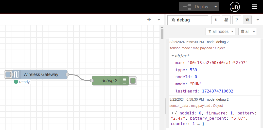
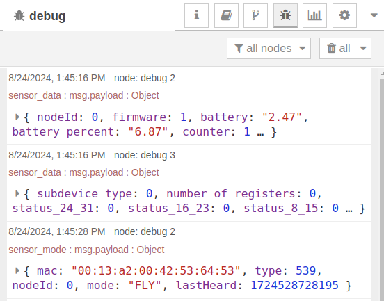
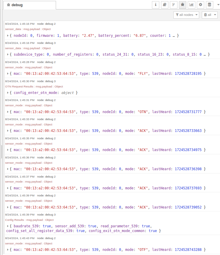
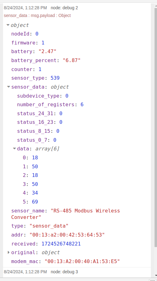
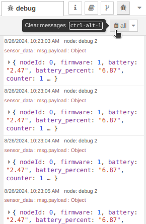
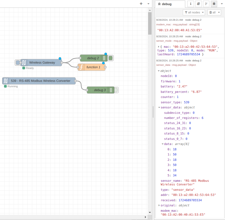
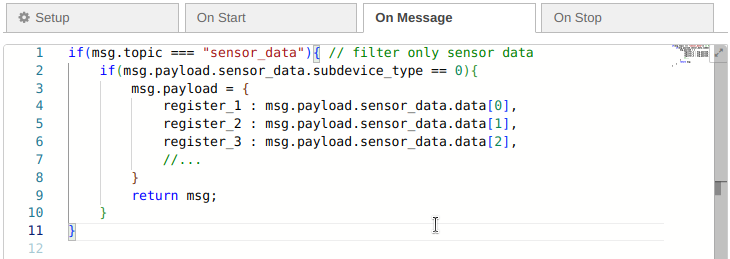
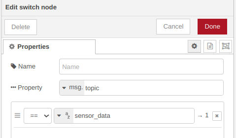
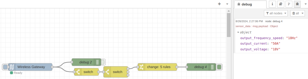
"topic": "sensor_data",
"payload": {
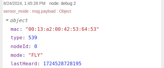
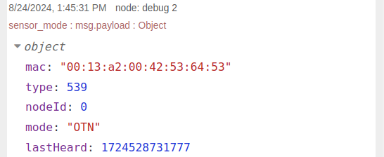
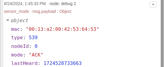
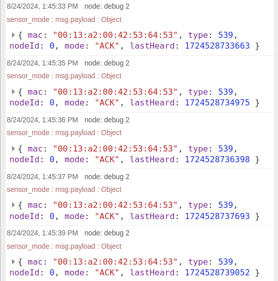
"nodeId": 0,
"firmware": 3,
"battery": "3.28",
"battery_percent": "98.56",
"counter": 26,
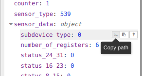
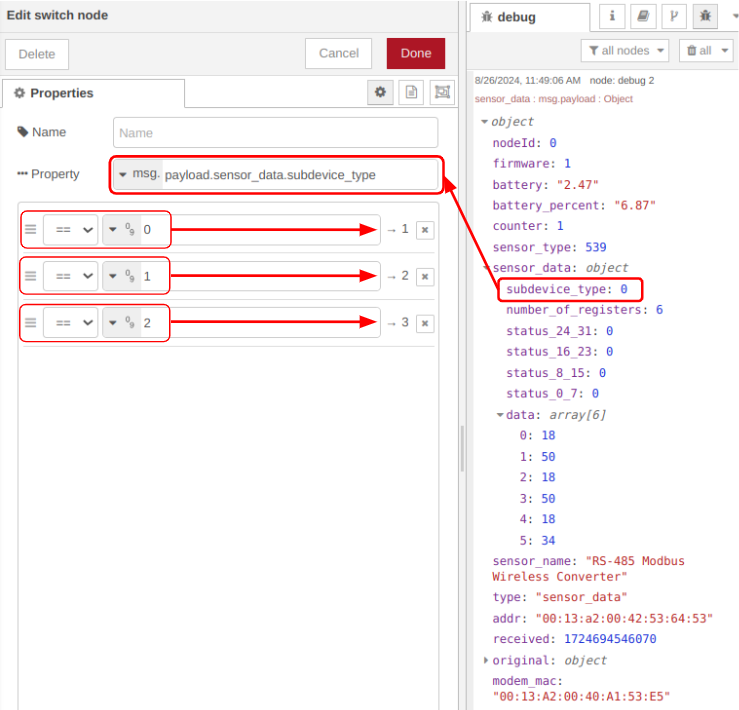
"sensor_type": 539,
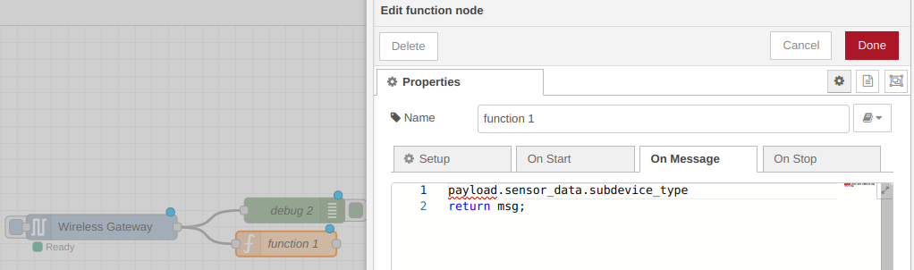
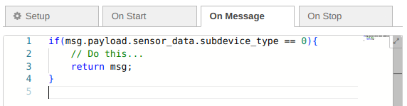
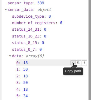
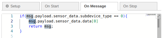
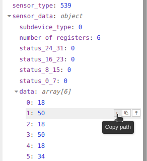
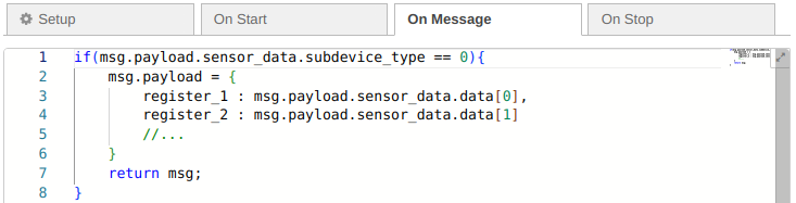
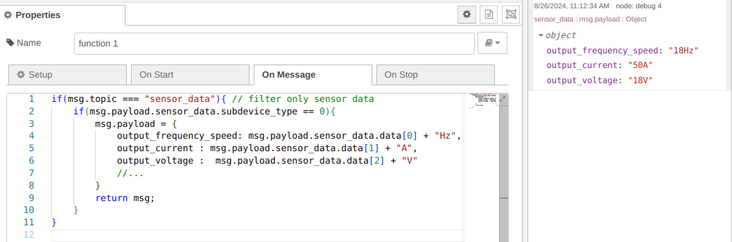
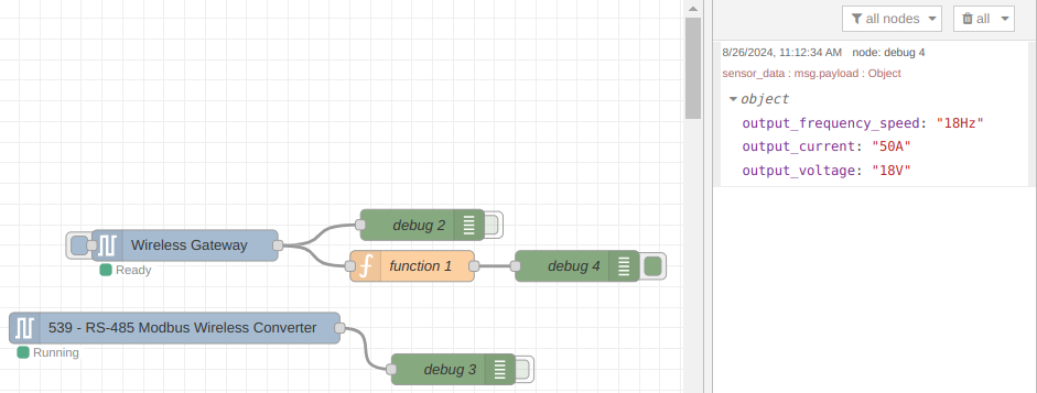
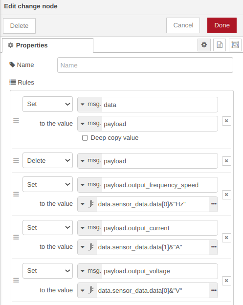
"sensor_data": {
"subdevice_type": 0,
"number_of_registers": 0,
"status_24_31": 0,
"status_16_23": 0,
"status_8_15": 0,
"status_0_7": 0,
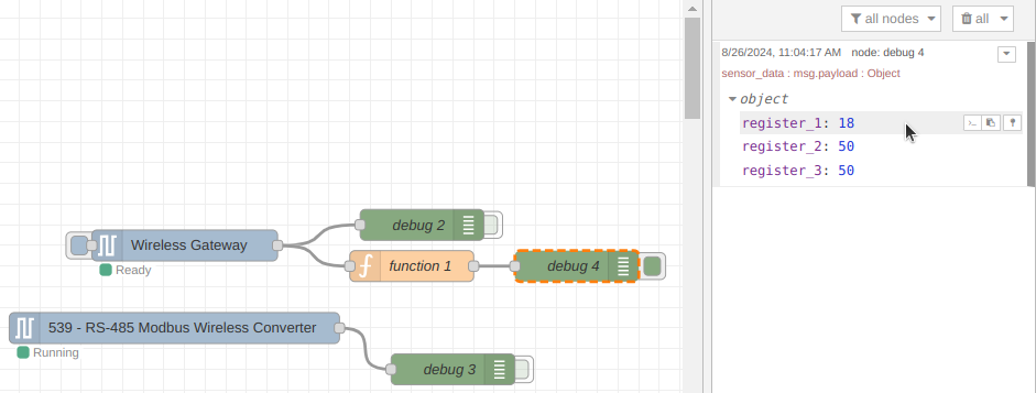
"data": [
0: 0,
1: 0,
2: 0,
3: 0,
4: 0,
5: 0,
6: 0,
7: 0,
9: 0,
10: 0
...
]
},
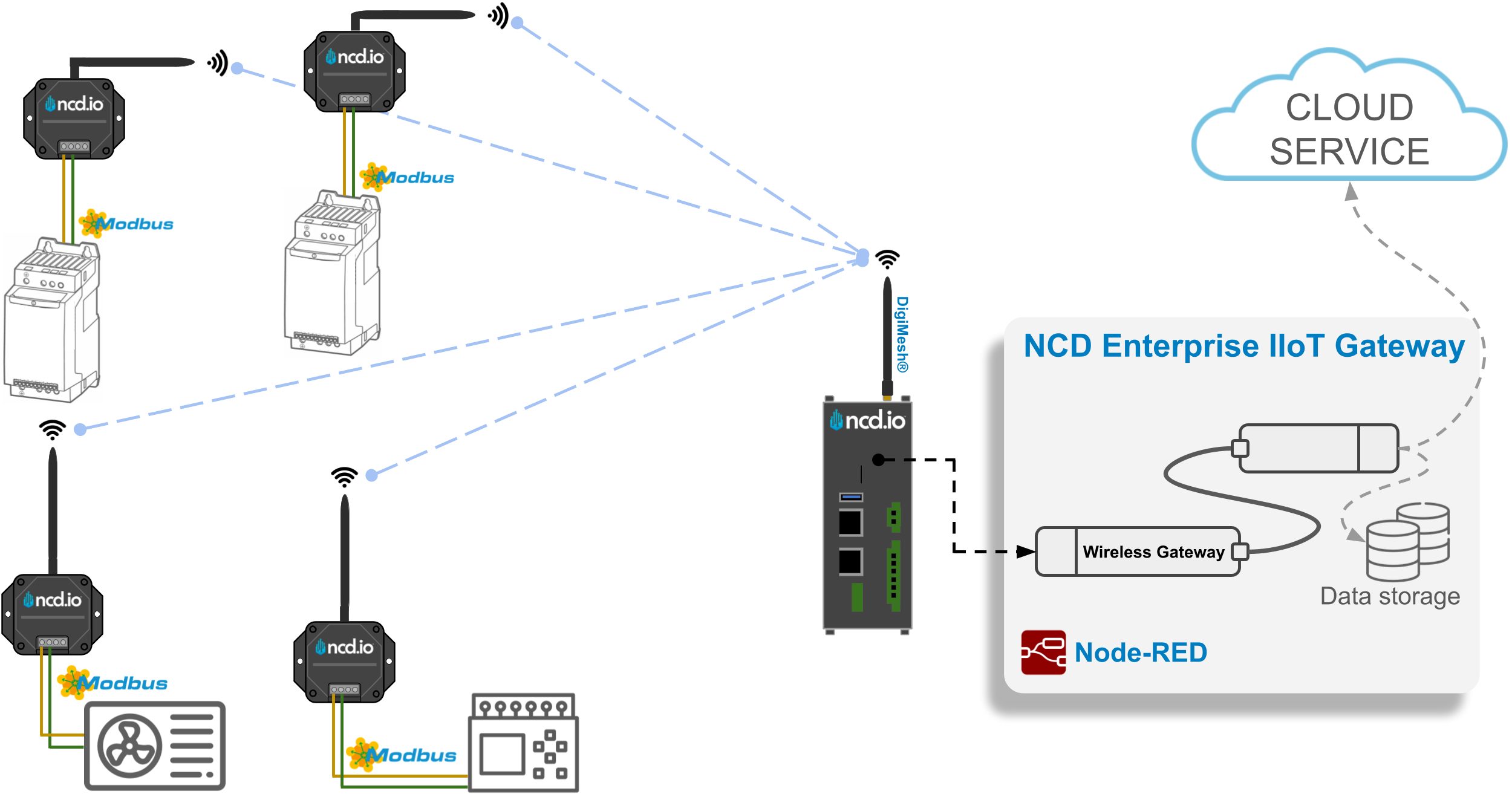
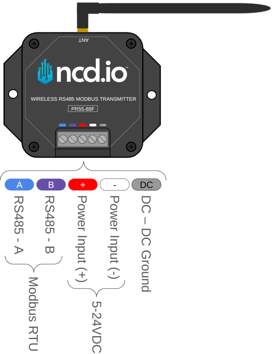
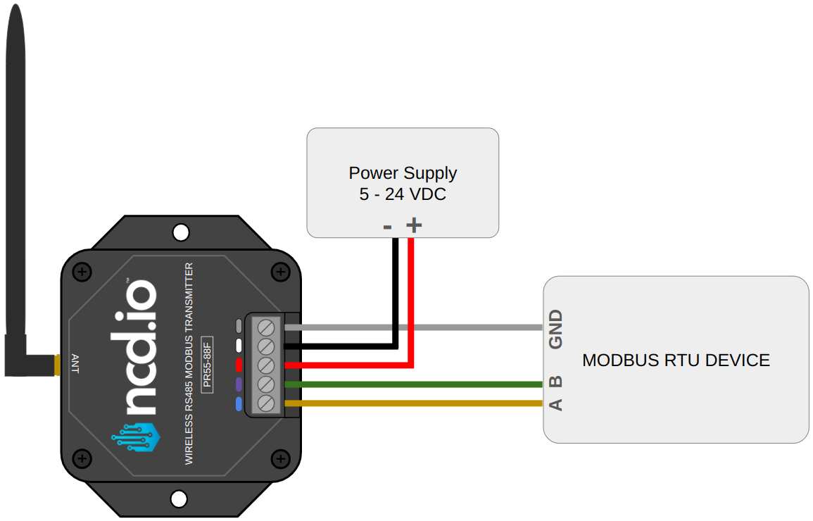
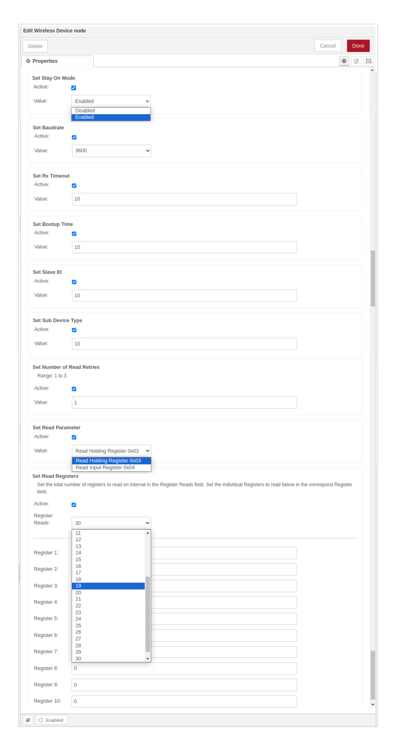
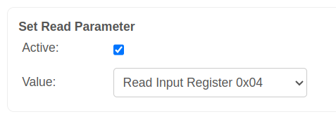
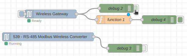
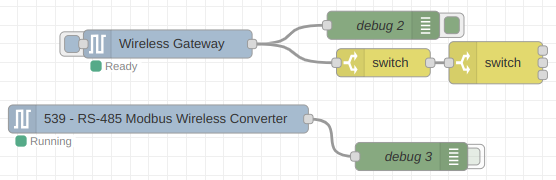
"sensor_name": "RS-485 Modbus Wireless Converter",
"type": "sensor_data",
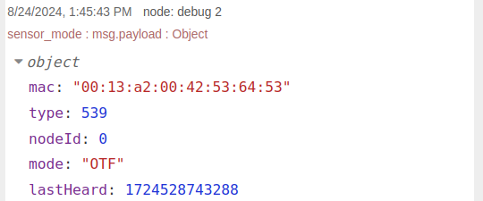
"addr": "00:13:a2:00:42:37:73:52",
"received": 1721424191583,
"original": {...},
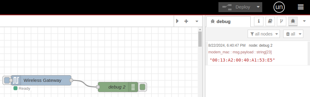
"modem_mac": "00:13:A2:00:41:F5:2C:D3"
},
"time": 1721424191584,
"_msgid": "d7f3341ef39225df"
}