This guide aims to address the most common issues that prevent NCD RS232 and RS485 devices from communicating correctly. It provides a step-by-step approach to troubleshooting, covering physical wiring validation, serial parameter configuration via Node-RED, and serial data debugging.
NCD Device: Refers to the NCD wireless hardware (e.g., PR55-28, PR55-34, or PR55-88F).
Field Device: Refers to the third-party RS232 or RS485 equipment physically connected to the NCD Device.
Wiring Connections
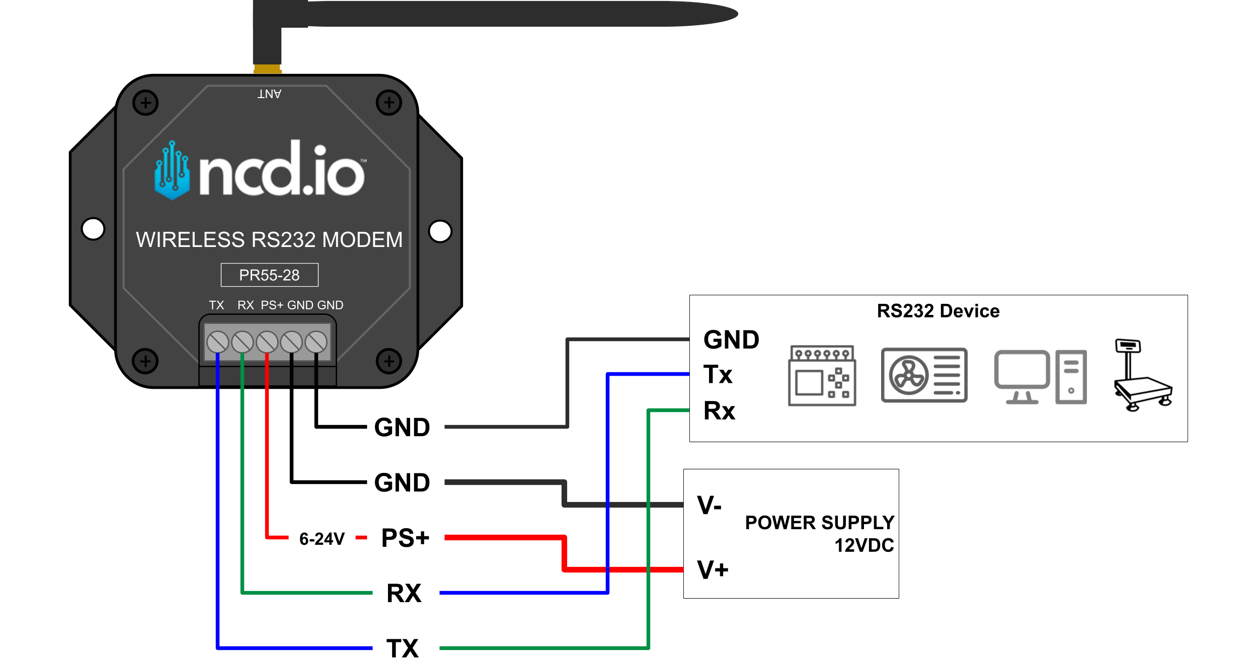
The first step in troubleshooting any industrial serial implementation is to verify the physical wiring between the NCD Device and the Field Device. Reversed TX/RX lines on RS232 or swapped A/B lines on RS485 are among the most common deployment mistakes.
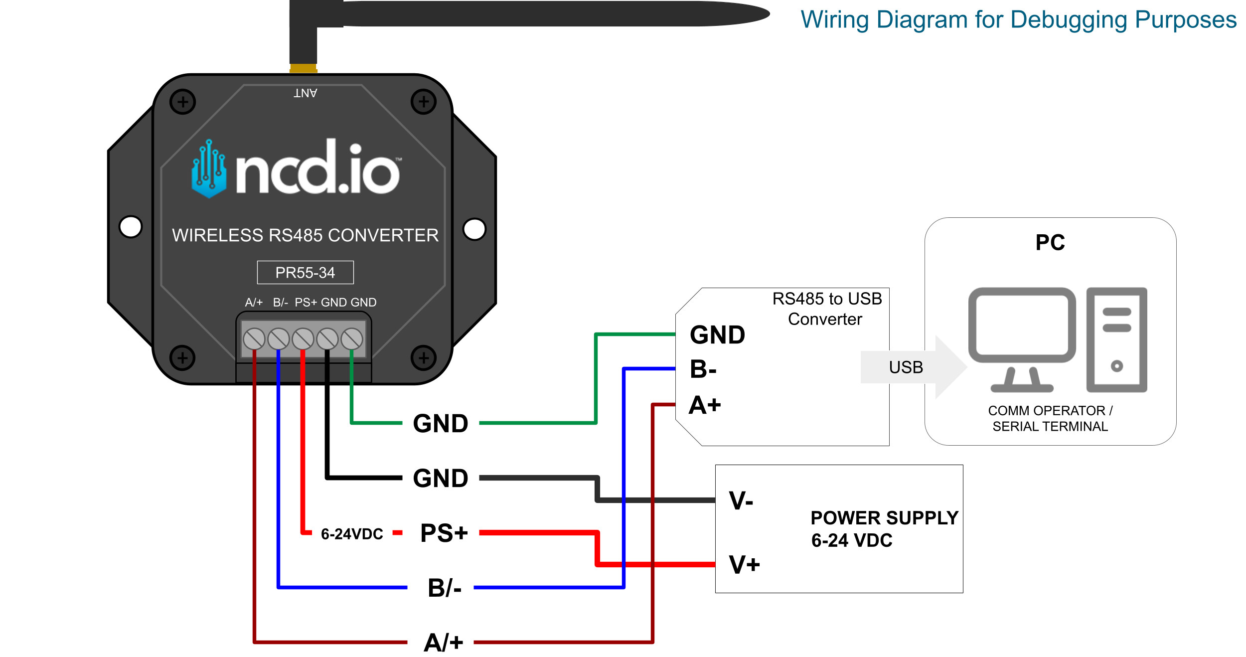
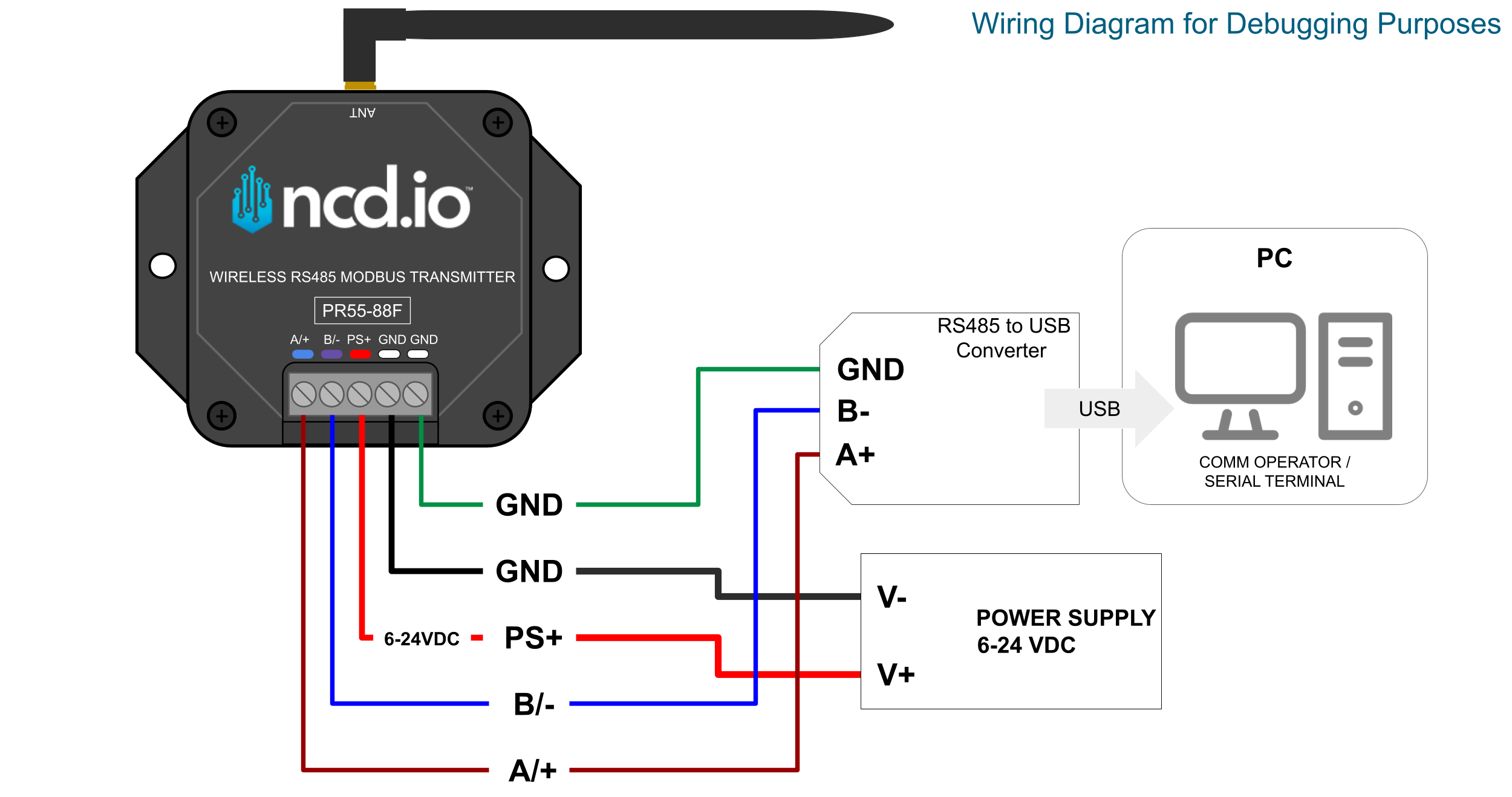
Please refer to your device’s specific wiring diagram to double-check the terminal block connections. Ensure that the ground connections are shared if required by your specific field environment, and verify that the power supply meets the necessary voltage requirements.
PR55-28
Click to Expand
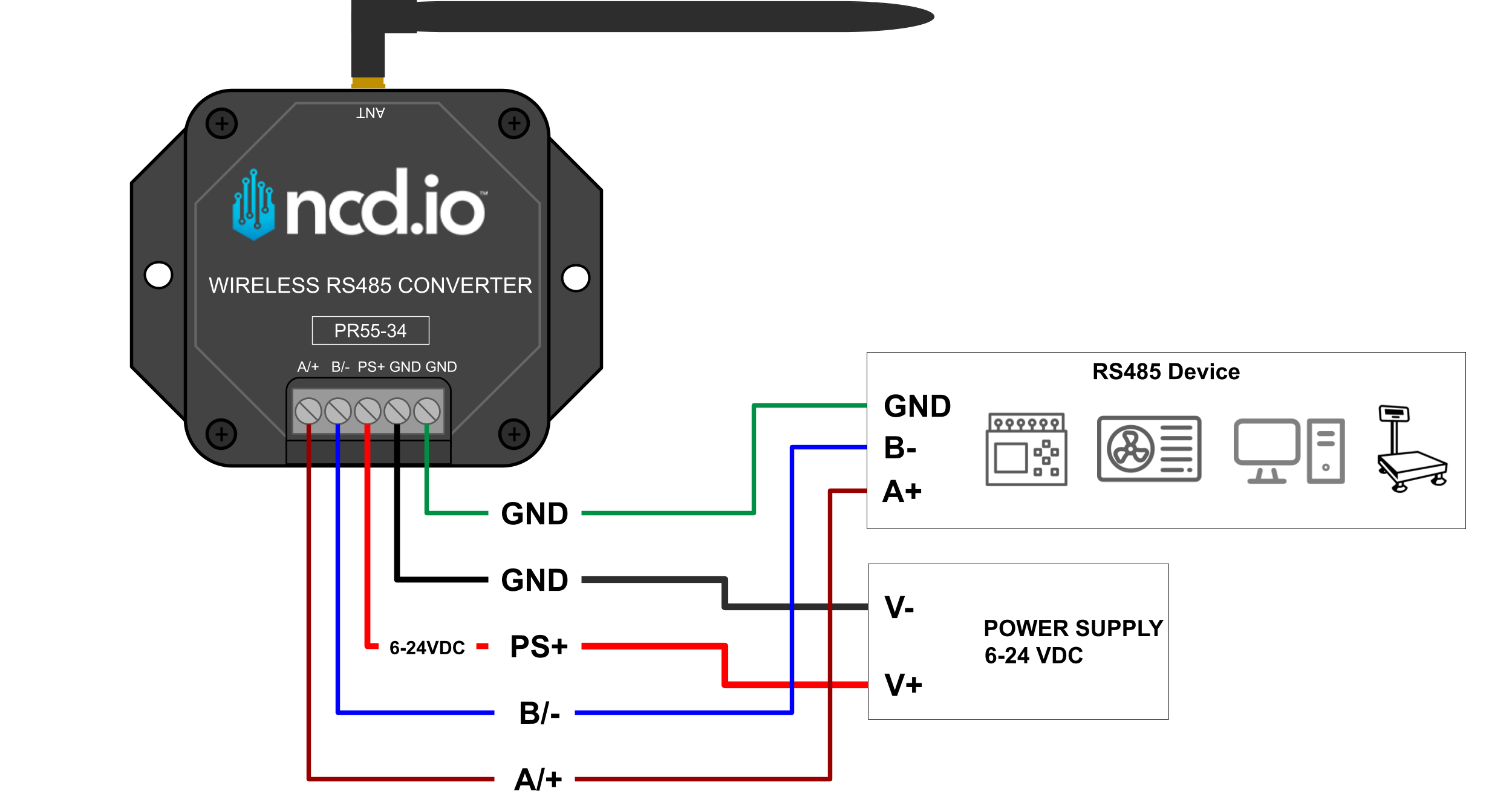
PR55-34
Click to Expand
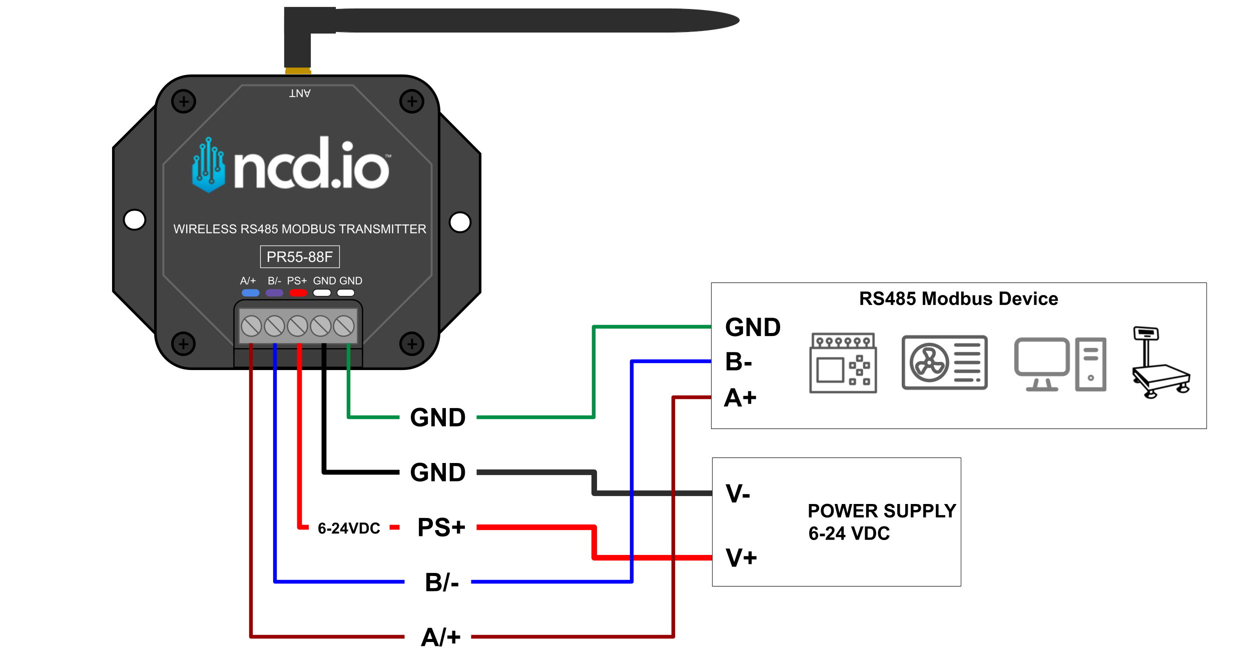
PR55-88F
Click to Expand
Serial Configuration
A frequent root cause of communication failure is a mismatch in serial settings between the NCD Device and the Field Device. Standard serial communications require identical Baud Rate, Parity Bit, Stop Bits, and Timeout configurations on both ends. You can find the required settings for your Field Device in its manufacturer datasheet or user manual.
NCD RS232 and RS485 devices ship with the following default serial configurations:
Baud Rate: 9600
Stop Bit: 1
Parity: None
Timeout: 10 milliseconds
If your Field Device requires different parameters, you must reconfigure the NCD Device using Node-RED to match them exactly.
Configuration
Hardware & Software Requirements
Gateway Users: The NCD Edge Gateway comes with Node-RED and the NCD Node-RED library pre-installed.
Modem Users: You will need an NCD Modem and a local PC running an installation of Node-RED along with the NCD Node-RED library.
Gateway: Open a web browser and navigate to [http://ncd-XXXX.local:1880](http://ncd-XXXX.local:1880) (replace XXXX with the last 4 digits of your Gateway’s MAC address).
Configure the Wireless Nodes
Wireless Gateway Node: This node acts as the entry point for all wireless network traffic. Gateway users do not need to alter this node. Modem users should configure it according to the standard setup documentation (See Installation Guide).
Wireless Device Node: This node represents your specific sensor or serial device. Double-click it in your workspace to access its properties.
Set the Wireless Device Node Properties
Name: Assign an arbitrary name for easy identification (Optional).
Serial Device: Select your primary communication interface from the dropdown.
Gateway: /dev/ttymxc2(115200)
Modem: COMx(115200) (replace x with your specific COM port).
Serial Device for Config: Select the same interface as above.
Mac Address: Manually type the exact MAC address of your NCD Device into the text field. If you are configuring a single device globally and do not wish to target a specific MAC, you can leave this field blank.
Sensor Type: Select the type that matches your hardware:
PR55-28: 1010 – RS232 Wireless Converter 1010
PR55-34: 1011 – RS485 Wireless Converter 1011
PR55-88F: RS485 Modbus Wireless Converter
Checkboxes: Enable Auto Config, OTF Config, and Wait for Network Formation.
Apply Serial Settings
Scroll down past the Retries property to find the serial settings (Baud Rate, Parity, Stop Bit, etc.).
To change a setting, check the Active box next to it. This tells Node-RED to push this specific setting during the next configuration cycle.
Enter or select your required values to match your Field Device.
Deploy and Trigger Configuration
Click Done, then click Deploy in the top-right corner to save your flow.
Attach a Debug node to the output of your Wireless Device node to monitor the process.
The NCD Device automatically enters configuration mode every hour (sending a FLY message). To force an immediate configuration, open the NCD Device enclosure and press the RST (Reset) button.
Monitor the debug window. Once you see the config_results message, the process is complete. Expand the message to verify your applied settings.
For the PR55-28 (RS232) and PR55-34 (RS485) devices functioning as a serial wire replacement pair, the hardware ships pre-configured in broadcast mode. For optimal reliability and reduced latency, it is highly recommended to configure both devices into Unicast mode so they only talk to each other.
NoteThe primary function of the PR55-28 (RS232) is to convert wireless NCD sensor data into serial RS232 data. To utilize this device as a wireless cable replacement, you must configure its operational profile to Auto Encoder Mode.
Example Scenario:
Device 1 MAC: 00:13:a2:00:42:3d:22:86
Device 2 MAC: 00:13:a2:00:42:3d:22:9d
Step A: Configure Device 1
Open the properties of the Wireless Device node targeting Device 1 (…22:86).
Scroll down to the Destination Address property.
Check the Active box and manually enter the last 8 characters of Device 2’s MAC address into the text input (423D229D).
Click Done, then Deploy.
Press the RST button on Device 1. Wait for the config_results message in the debug pane.
Step B: Configure Device 2
Open the properties of the Wireless Device node targeting Device 2 (…22:9d).
Scroll down to the Destination Address property.
Check the Active box and manually enter the last 8 characters of Device 1’s MAC address into the text input (423D2286).
Click Done, then Deploy.
Press the RST button on Device 2. Wait for the config_results message.
Serial Data Debugging
If you have verified the physical wiring and confirmed the serial settings match, the final troubleshooting step is to debug the raw serial data. This allows you to log exactly what the NCD Device is outputting to ensure the data structure (whether basic RS232 strings, RS485 payloads, or Modbus RTU frames) is intact.
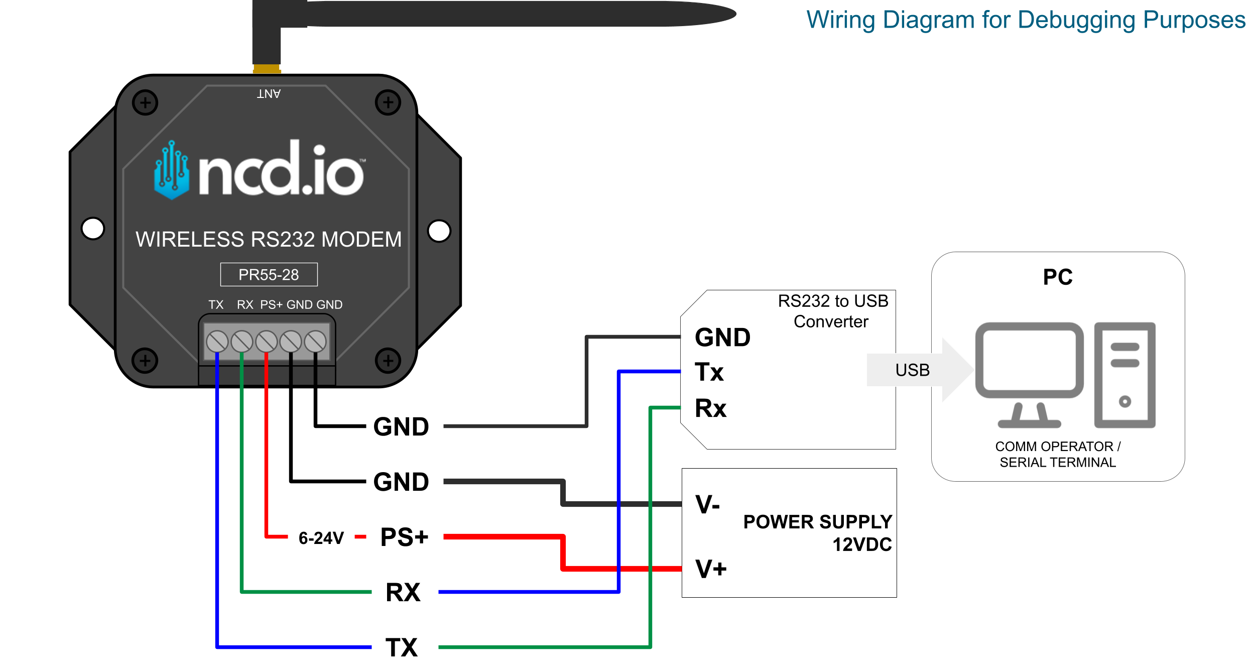
Connect the Hardware: Wire the NCD Device’s serial output terminals directly into your RS232/RS485 to USB adapter, and plug the adapter into your PC. (Refer to the debugging wiring diagram for specific pinouts).
Open Comm Operator: Launch your serial terminal tool.
Open Connection: Select the COM port assigned to your USB adapter. Ensure you configure the tool’s Baud Rate, Data Bits, Parity, and Stop Bits to exactly match the NCD Device’s current settings.
Analyze the Logs: Monitor the incoming data stream. You can format the output as Text, Hex, or Decimal depending on your protocol requirements.
Validate: Confirm that the requested commands and responses are formatting correctly for your specific application architecture.
PR55-28
Click to Expand
PR55-34
Click to Expand
PR55-88F
Click to Expand
Wire Replacement: Testing
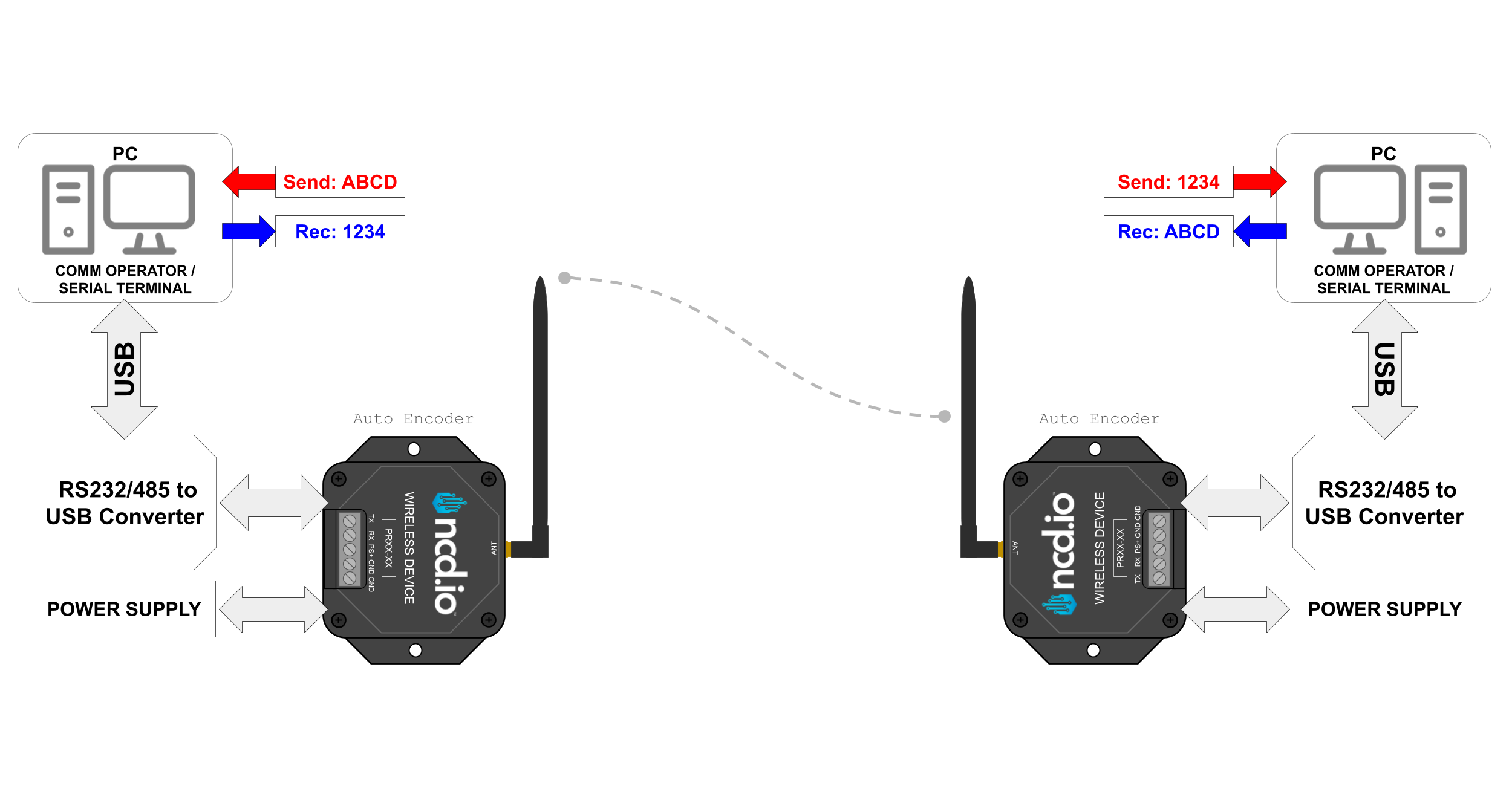
To verify wireless data communication between two NCD RS232/485 modems in a cable-replacement application, you can perform a loopback or end-to-end transmission test using a single PC. This setup utilizes two USB-to-RS232/485 serial converters alongside the Comm Operator software utility to monitor bidirectional data transmission (back and forth) simultaneously.
Required Hardware & Software Setup
Connect the Hardware: Plug both USB-to-RS232/485 converters into your PC and cross-connect them to the serial interfaces of your respective NCD modems.
Identify COM Ports: Open your operating system’s Device Manager to identify the specific COM port assigned to each USB converter.
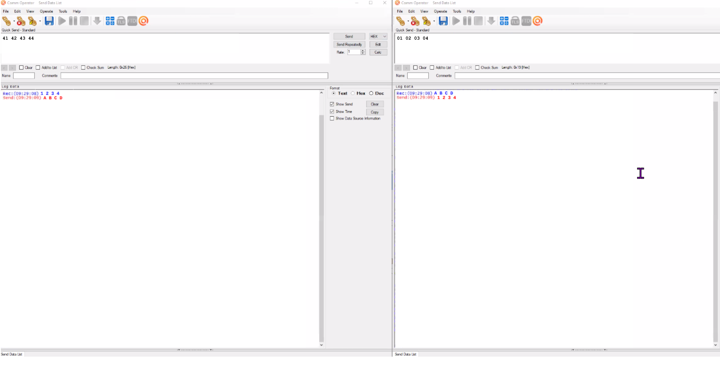
Configure Comm Operator: Open two independent windows or tabs within Comm Operator (one for each COM port). Configure both windows to match your device’s default serial communication parameters (e.g., Baud Rate, Parity, Data Bits, and Stop Bits).
Establish Connection: Click connect on both serial interfaces.
Once connected, enter a text or hexadecimal payload into the transmission terminal of the first COM port and click send. You should immediately see the data pass wirelessly through the NCD modems and populate in the receiving window of the second COM port. Successfully exchanging data in both directions confirms that your wireless link and hardware interfaces are functioning correctly.
Click to Expand
The following schematic provides a structural overview of this hardware testing configuration:
Click to Expand
Aditional Resources
Industrial Connectivity: Choosing the Right NCD RS-485 Device