Introduction
This article provides a comprehensive guide to configuring NCD sensor parameters using the Node-RED visual programming tool and the NCD library. It outlines the step-by-step procedure for both the Enterprise IIoT Gateway and the Wireless Modem. Additionally, it covers Manual and OTF Configuration modes, ensuring an intuitive and straightforward process while addressing key points for a successful configuration.
Requirements
To configure and acquire data from NCD sensors, you will need an Enterprise IIoT Gateway or an Industrial Wireless Modem (USB/Ethernet). You can find more information about these products at the following:
If you are still unsure whether your application requires a Gateway or a Modem, you can find a comprehensive guide on the differences between these two devices below:
Overview
The NCD library (@ncd-io/node-red-enterprise-sensors) provides nodes for configuring NCD sensor parameters through a visual interface, including selection boxes, dropdown menus, and text input fields. When adjustments are made, the library communicates with NCD sensors to transmit the user-defined configurations. The sensors then apply these settings and report back to Node-RED, confirming the status of each configuration.
As mentioned earlier, NCD sensor parameters can be configured using either a NCD Gateway or a NCD Modem. The following images provide an overview of the process for each device.
Gateway Overview
The Enterprise IIoT Gateway includes a wireless communication module for NCD sensors, along with Node-RED and the NCD Library pre-installed and ready to use. When you access Node-RED, you should see a pre-configured basic flow, which includes a Wireless Gateway node and a Debug node, allowing for faster deployment.
Modem Overview
Node-RED
Node-RED is a visual programming tool that provides a browser-based editor for creating applications by connecting predefined functions (nodes). Despite its technical nature, Node-RED offers a user-friendly interface. As an open-source project under the OpenJS Foundation, it is free to use with no subscription fees. You can install and run Node-RED locally on your PC, or, in the case of our Enterprise IIoT Gateway, it comes pre-installed and operates as a service. Node-RED, in conjunction with our Enterprise NCD library, forms a powerful tool for acquiring, managing, configuring, and uploading firmware through an intuitive interface. This combination offers a streamlined approach to optimizing the setup, configuration, and management of NCD sensor data.
NCD Enterprise Library
This library facilitates communication with and configuration of the NCD Wireless Sensor Line. It can be employed in conjunction with Node-RED to communicate and manage a Wireless Sensor Network using the Node-RED flow-based development tool on any platform. Additionally, as demonstrated, the library acts as an interface for uploading Firmware Updates to NCD Sensors. As mentioned earlier, this library is pre-installed on the Enterprise IIoT Gateway and is ready for immediate deployment.
Gateway Setup
NCD First Flow
When you first access the Node-RED interface from the Enterprise IIoT Gateway, you will see the flow on the right side. This flow consists of two nodes: the Wireless Gateway node and the Debug node.
- Wireless Gateway Node: This node is primarily used for debugging and configuring sensors. It is equipped with a button on the flow that switches the modem between configuration and listening modes. Whenever sensor data is received from any sensor on the network, this node will output a message containing all relevant information, as shown in the example below.
- Debug Node: The Debug node will receive messages from the Wireless Gateway node and display them in the Debug tab.
This is a preconfigured flow, meaning it is ready to receive data from NCD sensors. When a new NCD sensor connects to the DigiMesh wireless network and transmits data, the “Wireless Gateway” node automatically receives and processes the message. It then sends the message through its output terminal, allowing it to flow through the virtual connection cable to the “Debug” node. This node receives the message and displays it in the Debug window on the right side of the Node-RED editor.
Here is an example of the incoming sensor data—the data may vary depending on the type of sensor you are using.
Here you can find a complete getting started guide for accessing Node-RED from the Enterprise IIoT Gateway:
Modem Setup
If you are using your own Gateway or Computer, you will need a USB or Ethernet Modem, install Node-RED, and manually install the @ncd-io/node-red-enterprise-sensors library.
- The NCD USB Modem connects directly to the USB port of your PC or Gateway.
- The NCD Ethernet Modem connects to your local area network and receives sensor data from NCD sensors.
To install Node-RED on a Windows operating system and set up the basic flow (Wireless Gateway and Debug node), follow the steps outlined in this article:
Once you have installed Node-RED and the NCD Library, you’ll need to make the necessary configurations to enable communication between the Modem (USB or Ethernet), your PC, and Node-RED. Specifically, you need to configure the “Wireless Gateway” node to specify the physical port through which the PC will communicate with the Industrial IoT Wireless Modem.
To configure this, follow these steps:
- Drag and drop the “Wireless Gateway” node into your Node-RED workspace.
- Double-click the node to access its properties.
- Click the “Add new NCD Gateway config node” button to configure the physical port that your PC will use to communicate with the modem.
The process is illustrated in the following GIF.
NCD Configuration node
The Wireless Gateway node can be configured to communicate with both versions of the IIoT Wireless Modem. Each version requires its own specific configuration, as detailed below.
USB Serial connection
A serial connection is the simplest and most reliable connection to the wireless network. It doesn’t rely on any network layers like a TCP socket connection does.
Properties:
1. Name
- This allows you to enter a human readable name for identifying this config node
- If no name is chosen it will default to the text for the Serial Port field
2. Modem Type
- This allows you to choose between USB (Serial) or TCP (Ethernet/Network)
- If you are using an USB Modem you will might to choose USB (Serial)
3. Serial Port
- Select the correct serial port that your USB Modem/Wireless Module is mounted to.
4. Baud Rate
- Do not choose anything other than 115200 unless you have changed the baud rate on the Modem/Module manually.
5. Network ID
- Network IDs allow you to have multiple groups of sensors, repeaters, and Gateway/Modems in a single area without interfering with each other
- The default value is 7FFF
- We do not recommend changing this value without specific purpose
- Make sure to change the Network ID of the sensors you want to be on this network BEFORE changing the Network ID here.
6. Add RSSI to incoming packets
- Selecting this box will add a signal strength indicator to all incoming comms
- Selecting this option will have a negative, but generally negligible effect on the Wireless Communication throughput
TCP Socket Connection
A TCP socket connection allows the PC running Node-Red to be in an out of the way location while still receiving the sensor data from a Network Modem placed in a more central location. These communications heavily rely on the network that the Modem are on. It is recommended to put the PC and the Ethernet Modem on the same network or have an IT team to oversee the communications if this option is used.
Properties:
1. Name
- This allows you to enter a human readable name for identifying this config node
- If no name is chosen it will default to the text for the Serial Port field
2. Modem Type
- This allows you to choose between USB (Serial) or TCP (Ethernet/Network)
- If you are using an Ethernet Modem you will might to use TCP (Ethernet/Network)
3. TCP Port
- Select the TCP Port that the modem is listening on
- The default TCP Port for our Ethernet Modems is 2101
4. IP Address
- The IP address of the Ethernet Modem on the network
- It is recommended to have the Ethernet Modem use a Static IP address so that this value never needs to change.
5. Network ID
- Network IDs allow you to have multiple groups of sensors, repeaters, and Gateway/Modems in a single area without interfering with each other
- The default value is 7FFF
- We do not recommend changing this value without specific purpose
- Make sure to change the Network ID of the sensors you want to be on this network BEFORE changing the Network ID here.
6. Add RSSI to incoming packets
- Selecting this box will add a signal strength indicator to all incoming comms
- Selecting this option will have a negative, but generally negligible effect on the Wireless Communication throughput
Once you have completed configuring the “Wireless Gateway” node, click the “Add” and “Done” buttons. Then you could add a debug node and connect it, in order to see the incoming messages. Finally, click the “Deploy” button to save and apply the changes.
Getting Sensor Data
Before proceeding with configuring the parameters of NCD sensors, you might need to establish communication between the NCD sensor and the Gateway or Modem. This communication is established automatically, with no configuration required. The only requirements are to power on the NCD sensor (which is off by default) and ensure that the Gateway or Modem (USB/Ethernet) is powered and fairly close to each other to ensure communication. As soon as you power on the NCD sensor, it will automatically establish a connection with nearby DigiMesh devices. The following image illustrates this process for both the Gateway and the Modem; the connection is automatic.
RUN Message
As soon as the wireless connection between the NCD sensor and the Gateway or Modem is established, the NCD sensor automatically transmit an initial message, known as the RUN message.
A RUN message received simply indicates that the sensor indicated in the msg.payload.mac is powered up and communicating with the wireless network. An example RUN message is showing in the next image:
{
"topic": "sensor_mode",
"payload": {
"mac": "00:13:a2:00:00:00:00:00",
"type": 1,
"nodeId": 0,
"mode": "RUN",
"lastHeard": 1721424191056
},
"time": 1721424191056,
"_msgid": "f41dad7923ece27c"
}
Sensor Data Message
Sensor data is the message that will come from a Wireless Gateway Node after RUN message. These messages can be discerned from other message types by the topic which will always be “sensor_data” to the right is an example of a Sensor Data message.
- nodeID
- A user configurable parameter allowing a user to input a simple id for a particular sensor
- firmware
- This identifies the firmware version of the sensor sending the packet
- battery
- The current voltage level of the batteries at the time of transmission
- battery_percent
- The current battery percent at the time of transmission
- counter
- The number of transmissions since boot or counter rollover
- sensor_type
- The machine identifiable type of the sensor
- sensor_data
- Object containing all sensor data related to the NCD sensor
- sensor_name
- Human Readable Sensor Type Identifier
- type
- An easily passed message type declaration
- addr
- The unique identifier of the sensor that transmitted the data
- received
- Epoch indicator of when the data was received by Node-Red
- original
- Auxiliary information on the packet and underlying protocol
- modem_mac
- The unique identifier of the Gateway/Modem that received the data
- Primarily used to tie locations/projects to sensors/sensor data
{
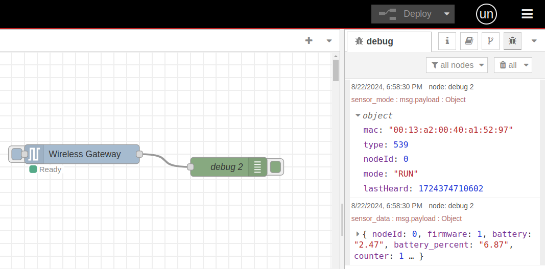
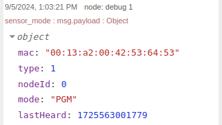
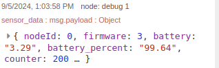
"topic": "sensor_data",
"payload": {
"nodeId": 0,
"firmware": 1,
"battery": "3.28",
"battery_percent": "98.56",
"counter": 1,
"sensor_type": 1,
"sensor_data": {
"variable_1": 0,
"variable_2": 0,
"variable_3": 0,
...
},
"sensor_name": "NCD Sensor ID",
"type": "sensor_data",
"addr": "00:13:a2:00:00:00:00:00",
"received": 1721424191583,
"original": {...},
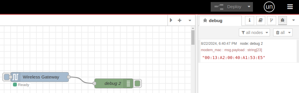
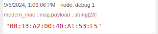
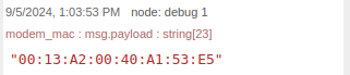
"modem_mac": "00:13:A2:00:00:00:00:00"
},
"time": 1721424191584,
"_msgid": "d7f3341ef39225df"
}
These two messages, RUN and sensor_data, are the default basic data that each NCD sensor will send to the Gateway or Modem. Note that the RUN message is sent only once each time a connection is established with the Gateway or Modem, while the sensor_data message is sent periodically and contains the measured field values and other data from the sensor. Once these two messages are received, you can be confident that you have a link with the sensor and can proceed with the configuration.
Wireless Device Node
Our NCD Node-Red library lets you configure any of NCD sensors easily using the “Wireless Device” node, simply by adjusting a few fields in your Node-RED flow and triggering a configuration update either through the RESET and CFG buttons on the sensor or waiting for a FLY message sent (we will explain this modes later in this article).
Begin the configuration process by dragging the “Wireless Device” node into the workspace, as shown in the following image:
Node Properties
Basic Properties
These configurations are responsible for configuring the Wireless Device node and how Node-RED should interact with NCD Sensors.
- Name
- Arbitrary name of this node
- Primarily used for easy identification in the flow
- Serial Device*
- The primary communication interface used to receive data from the sensor
- Clicking the edit icon will take you to a submenu to edit the particulars of the device chosen in the Serial Device dropdown
- To add a new configuration option you will want to choose “Add new ncd-gateway-config…” from this dropdown
- Serial Device for Config
- A secondary communication interface used to configure sensors without losing sensor data
- If no option is selected the communication interface selected under Serial Device will be used for configuration
- A second modem will be required to make full use of this option
- Mac Address
- Using this field allows you to choose a specific sensor that corresponds to this Wireless Device node
- Leaving this field blank allows any sensor of the type chosen under the Sensor Type field to correspond with this Wireless Device Node
- A search icon on the right can be clicked to search for Wireless Devices that the Serial Device has heard from to auto fill information for that device
- Sensor Type*
- This field limits the sensors that correspond to this Wireless Device node to a particular type of sensor
- Auto Config
- Checking the box next to this field tells Node-Red that the sensor(s) corresponding to this Wireless Device node should be configured when put into Configuration Mode manually
- OTF Config
- Checking the box next to this field AND having Auto Config checked tells Node-Red that the sensor(s) corresponding to this Wireless Device node should be configured when a FLY message is detected
*Required
General Sensor Configuration
All NCD sensors share general sensor configurations, which are the basic settings that allow for the adjustment of certain operational parameters of the sensor. Additionally, each sensor may have its own specific configurations, such as calibration, stay-on mode, filtering, among others. For details on these specific configurations, please refer to the corresponding documentation. Below, each of these properties is outlined along with a description of each.
- Wait for Network Formation
- This option sends three commands to all local devices on the wireless network to help form the mesh network
- Destination Address
- This option will tell the sensor to ONLY send its data to a single receiver.
- By default the sensor sends data in Broadcast Mode.
- Network ID
- This option allows you to change the Network ID that the sensor will use to report its data while in RUN module
- You will need to make sure that a Gateway or Modem is configured to use this network ID in order to receive sensor data from it after configuration
- Node ID and Delay
- Node ID
- Node ID allows you to set an easy to understand unique ID for a particular sensor
- Delay
- Delay is the time in seconds between sensor data reading transmissions
- Node ID
- Power
- This option allows you to set the transmission power level of the sensor
- Retries
- Sets the maximum number of retries the sensor will attempt before considering a packet transmission failed
Destination Address - Transmission Methods
Broadcast Transmission
Broadcast means to transmit the same data to all nodes on a network. These transmissions are propagated throughout the entire network so that all possible nodes receive the transmission.
Unicast Transmission
A unicast transmission consists of sending messages to a single node (Gateway or Modem) on the network that is identified by a unique 64-bit address.
Source: Broadcast gif
Source: Unicast gif
Once you have checked the box and configured the desired settings for the sensor, the next step is to click the “Done” button located at the top right. You might want to connect a debug node to the output of the “Wireless Device” node, in order to see the messages. Then, press the “Deploy” button to save and apply the changes.
Sensor Configuration Modes
Once this procedure has been completed, it is time to enable the configuration mode. If the sensor features Automatic Configuration (OTF), no additional steps are required. The next time a message FLY is received from the sensor, it will inquire whether any configuration needs to be applied. In this case, the gateway or modem will confirm if there are pending configurations and will automatically begin the configuration process. Conversely, if the sensor does not have the Automatic Configuration feature, it is necessary to manually set the sensor to configuration mode.
Manual Configuration
Configuration Mode
To use the “Manual Configuration” mode, an additional step is required within the Node-RED flow. This step involves setting the “Wireless Gateway” node to configuration mode. To do this, click the button embedded in the node on the left side. An example of this procedure is shown in the following image:
The manual mode is available on all NCD enterprise sensors. This configuration mode is enabled by the user, who must access the interior of the sensor. Each sensor has its own way to access, so we recommend checking the user manual or datasheet for specific instructions. Once you access the interior of the sensor, you will observe, among other components, two push buttons: the RESET button and the CONFIGURATION button.
Sensors can be manually put into configuration mode:
- Press and release the RESET button
- Immediately press and hold the CONFIGURATION button
- Hold the CONFIGURATION button for about 5–8 seconds
- Release the CONFIGURATION button
PGM Message
Once you put the sensor into configuration mode, it automatically transmit a PGM message to the Gateway or Modem. A PGM message received indicates that the sensor indicated in the msg.payload.mac has been put into configuration mode using the onboard buttons. An example structure of a PGM message is shown next image:
{
"topic": "sensor_mode",
"payload": {
"mac": "00:13:a2:00:00:00:00:00",
"type": 1,
"nodeId": 0,
"mode": "PGM",
"lastHeard": 1721424000999
},
"time": 1721424000999,
"_msgid": "36ac745134de68ee"
}
Once both the “Wireless Gateway” node and the NCD Sensor are enabled in configuration mode, the process of configuring the user-defined parameters will begin automatically. In the Debug window, you will be able to see messages indicating the configuration process. An example of this process is shown in the following image:
Understanding Manual Configuration Messages
1. Pressing the “Wireless Gateway” node button to set the node to “Configuring” mode will automatically trigger the node to send a message “modem_mac” to the debug node, displaying its MAC address.
This message comes from the Wireless Gateway node
2. When placing the NCD Sensor into configuration mode by following the previously mentioned RESET and CFG button sequence, the sensor will transmit the PGM packet as described.
This message comes from the Wireless Gateway node
3. This action initiates the configuration process by the “Wireless Gateway” node. For each configured property, the NCD Sensor must send an ACK packet, indicating successful receipt of the configuration. Note that an ACK message is required for each configuration parameter set.
This message comes from the Wireless Gateway node
4. Once all configurations have been made you will see a “Config Results” message displaying the result of the configurations. This allows us to confirm which configurations were applied, and if the value is true, it means the configuration was successfully set.
This message comes from the Wireless Device node
5. Once the “Wireless Gateway” node is set to “Ready” mode, it will again send a message with its MAC address.
This message comes from the Wireless Gateway node
6. Pressing the RESET button on the NCD Sensor will return it to “Running” mode and it will send a DATA message.
Automatic Configuration OTF
Some of the NCD Sensors supports configuration while in Run Mode. We call this configuration OTF or On the Fly. This configuration is initiated by a sensor_mode message from the Sensor with the mode of FLY. These messages are sent over the standard Run Mode wireless network so there is no need to change the Wireless Gateway nodes mode or manually manipulate the buttons on the sensor.
A FLY message indicates that the sensor is in RUN mode, but is entering a temporary state where it can be configured. Once the sensor sends a FLY message Node-RED has 2 seconds to respond with a configuration or extend this temporary configuration mode. If Node-RED has a “Wireless Device” node with Auto Config and OTF Config selected corresponding to the sensor that sent the FLY message then Node-RED will begin to configure that sensor. An example FLY message can be found on the right.
{
"topic": "sensor_mode",
"payload": {
"mac": "00:13:a2:00:00:00:00:00",
"type": 23,
"nodeId": 0,
"mode": "FLY",
"lastHeard": 1721424191766
},
"time": 1721424191767,
"_msgid": "5f6f01b6651b2f82"
}
This FLY message tells Node-Red that the sensor is ready for configuration changes. Node-Red has two seconds to respond with a configuration or extend this temporary configuration mode.
An example of the automatic configuration process, where some sensor parameters are configured, is shown in the following image:
Understanding OTF Messages
1. Sensor sends FLY message: This is now and indication that the sensor is checking if the modem wants the sensor to go into a temporary configuration mode. If no response is detected within ~2 seconds, then the sensor will go back to sleep as usual.
This message comes from the Wireless Gateway node
2. Wireless Gateway responds with a command, this is the Gateway/Modem telling the sensor that it should go into configuration mode.
3. Sensor responds with an OTN Message. This message indicates that the sensor successfully extended the configuration window indicated by the FLY message.
This message comes from the Wireless Gateway node
This message comes from the Wireless Device node
4. At this point the Wireless Gateway node will send all of the configuration commands. For each configuration command the NCD Sensor will respond with an ACK message.
This message comes from the Wireless Gateway node
5. Once all configurations have been made, the Wireless Gateway node will send another command to tell the sensor to return to normal operation. You will see a “Config Results” message displaying the result of the configurations. This allows us to confirm which configurations were applied, and if the value is true, it means the configuration was successfully set.
This message comes from the Wireless Device node
6. The sensor responds with an OTF message This indicates to the Gateway/Modem that it is no longer accepting configuration commands.
This message comes from the Wireless Gateway node
The FLY message is the sensor letting Node-RED know that it is ready to enter OTF or On The Fly mode. If Node-RED is configured to make configuration changes through OTF mode then Node-RED will send a command to put the sensor into configuration mode and once the sensor is in configuration mode it will make all configured changes.
In essence it is an Over The Air configuration that doesn’t require manual manipulation of the sensor.
Summary
In this article, we provided a step-by-step guide for configuring the NCD sensors using the Enterprise IIoT Gateway or the Industrial Wireless Modem (USB/Ethernet) through Node-RED with the NCD library. We aimed to cover all necessary aspects for correctly configuring these parameters. As you observed, the process is quite straightforward and intuitive; you just need to pay attention and follow the steps according to the type of NCD sensor or Gateway/Modem you are using. We also covered the prerequisites and included a brief description of the messages or packets that the NCD sensor sends to Node-RED during normal operation and configuration mode.
Thank you, NCD Team