DisclaimerRunning this script may modify your system configuration and install software packages. This guide is provided for convenience and for installation instructions as recommended by Nodejs and Node-RED.
The NCD Industrial IoT Wireless to Ethernet Modem connects to your local area network and receives sensor data from NCD sensors supporting a single client connection. Our IoT Wireless Ethernet Modem makes it easy communicate with NCD wireless sensors over Ethernet by simply opening a TCP/IP port and watching for incoming data to arrive as sensor data is broadcast. You can then leverage Node-RED to access, manage, and adjust certain settings on your NCD sensors.
Industrial IoT Wireless to USB Modem
The NCD Industrial IoT Wireless to USB Modem plugs directly into your PC’s USB port, allowing it to receive sensor data from NCD devices. The modem appears as a COM port on your computer, simplifying programming tasks. Use the NCD USB Modem to configure your long-range NCD wireless sensors. Simply connect the modem and open the virtual serial port to start receiving sensor data streams from all nearby sensors. You can then leverage Node-RED to access, manage, and adjust certain settings on your NCD sensors.
NoteAll NCD Modems also acts as a repeater for NCD Long Range Wireless Sensors to extend range. No additional settings are required as this is a passive feature of the device once powered up.
Overview
This image shows the basic architecture of the system we will discuss in this article. The NCD field sensors transmit their data wirelessly via DigiMesh to a receiving modem. This modem then transmits the signal to a Windows computer via a USB or Ethernet connection. The computer receives the data, allowing users to manage and even configure sensor parameters using Node-RED through our NCD library.
System Requirements
The following points are required for the development of this procedure:
Have Google Chrome web browser installed on your Windows computer.
Disabling antivirus software during the installation process might be necessary.
NoteWe have tested the Installer on freshly installed Windows 10 and Windows 11. It is possible you might encounter issues during execution. If this happens, you can report them on our forum, and we will provide support as soon as possible.
Installation Files
To download the installation files, follow these steps:
Click on the following GitHub repository link.
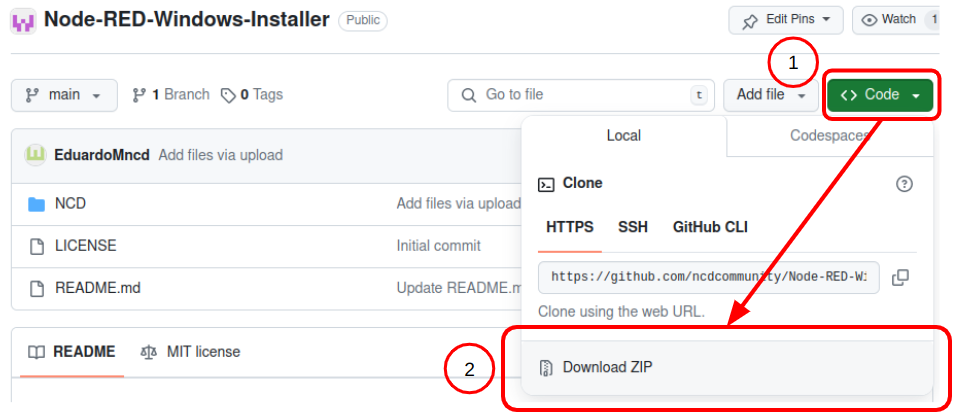
Once on the repository page, locate the ‘Code’ button.
Click the ‘Code’ button and select the ‘Download ZIP’ option, as illustrated in the following image:
Once the ZIP file download is complete, unzip it. Then, navigate to the extracted folder and copy the “NCD” folder to your Windows desktop.
Install and Execute Node-RED
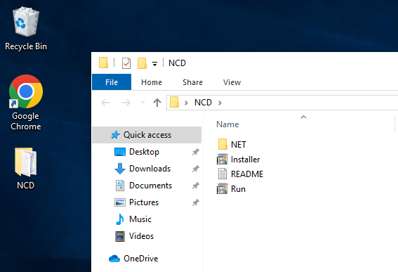
NCD folder
Open the “NCD” folder. Inside, you’ll find the files needed to install and run Node-RED on Windows. Here’s what you’ll see:
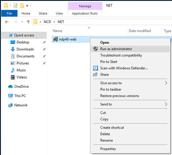
Installing .NET
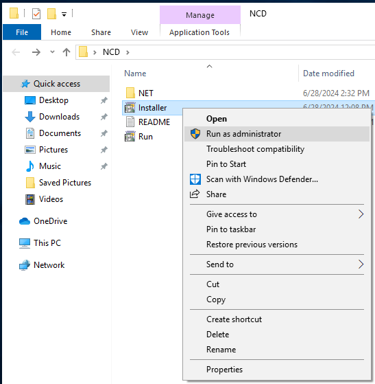
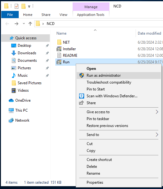
The first step is to verify that you have .NET installed, a framework required to run the Node-RED installer on Windows. To do this go to and open the “NET” folder, inside you will find an installer (ndp48-web), right click on it and select the “Run as administrator” option to run the installer:
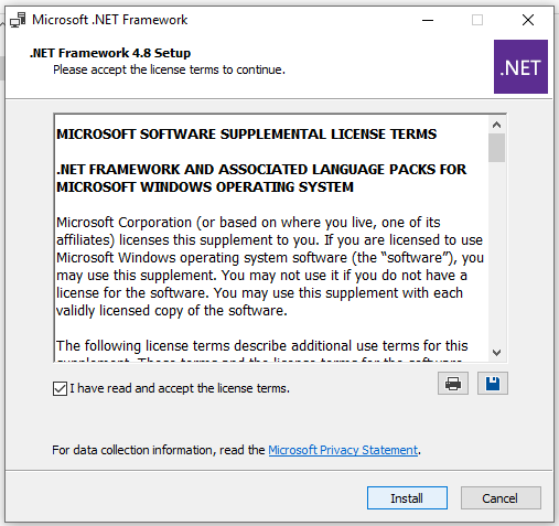
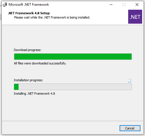
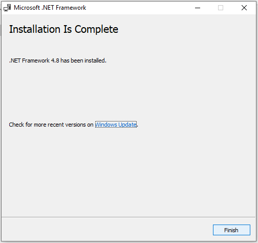
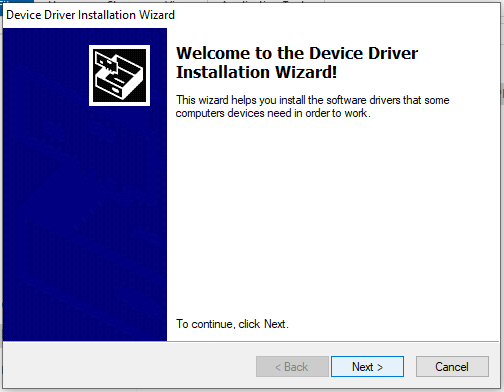
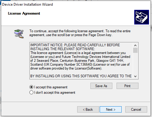
Once you select “Run as administrator,” the .NET installer will launch. Be sure to read and accept the license terms before proceeding with the installation. The following images provide a summary of the steps involved:
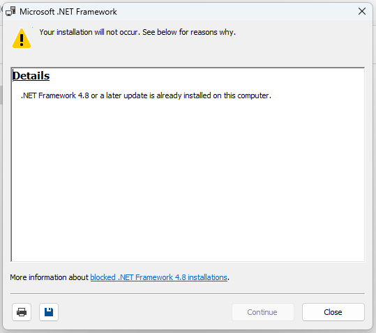
NoteIf you already have the .NET 4.8 framework installed on your PC, the installer will display a message like the following (just click on the "Close" button):
Execute Installer
After verifying or installing the .NET framework, proceed with the Node-RED installer. This installer will handle setting up the necessary prerequisites for Node-RED and the @ncd-io/node-red-enterprise-sensors library, followed by the Node-RED installation itself. To launch the installer, right-click on it and select “Run as administrator”:
This will launch the installer in a command terminal window (cmd). The installation process will be automatic, and you’ll see progress for each package being installed. Be patient, as some packages may take a while. The following images only provide a sample of the installation process for each package.
Click to expand
Chocolately
Click to expand
Python
Click to expand
VisualStudio Build tools
Note: It is possible take a long time during Visual Studio Build tools installations, be patient.
Click to expand
Node.js & npm
Click to expand
Node-RED
Execute Run
If the installer completes without errors, Node-RED has been successfully installed on your Windows PC. Now, let’s launch Node-RED and access the node editor. This is where you’ll build the logic to interact with your sensors, such as reading data or configuring parameters, using the NCD library (which we’ll install in a later step).
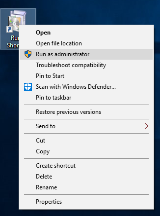
To run Node-RED simply right click on the file “Run” and select the option “Run as administrator”:
This file will automatically launch Node-RED and open the Node Editor in a new web browser window. (The Node Editor is accessed through Google Chrome in this case.) You should see something like the following:
Click to expand
Running Node-RED cmd
Click to expand
Node-RED Node Editor
NoteTo stop Node-RED, simply close the web browser window where you accessed the Node Editor then close the cmd tab that opens during the execution of the "Run" file.
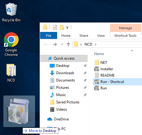
Plus: Create a shortcut
You can also create a shortcut for the Node-RED “Run” file and place it on your Windows desktop for easier access. This way, you can launch Node-RED from Desktop:
Installing NCD Enterprise Library
To manage and configure NCD Wireless Sensors Line, you’ll need to install the NCD library for Node-RED (@ncd-io/node-red-enterprise-sensors). The process is straightforward and can be performed from the Node-RED interface. You should run Node-RED and access the editor, then: follow these steps:
1. Go to main menu located in the top right corner of the Node-RED editor and select Manage palette.
Click to expand
2. Within the Palette section, navigate to the “Install” tab. In the search box, type “@ncd” and you’ll see the library appear:
Click to expand
3. Clic on Install button (Installation may take some time, be patient.).
Click to expand
4. You will see the added nodes.
Click to expand
5. Clic on “Close” button.
Click to expand
6. You will see the NCD nodes on Nodes Palette.
Click to expand
USB Driver
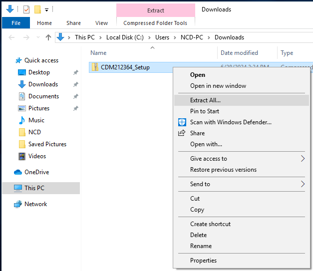
In most cases, simply connecting the device will prompt Windows to automatically install the driver. However, if you connect the Industrial IoT Wireless to USB Modem to your PC and it doesn’t appear as a COM/Serial port (verifiable in Device Manager), you’ll need to install the driver manually. Here are the steps to follow:
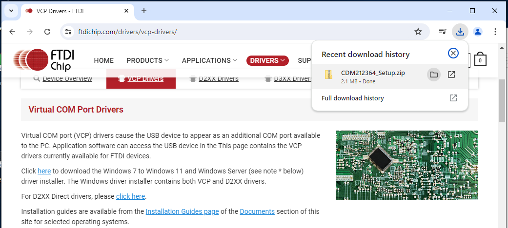
Click on the corresponding link to start downloading the “.ZIP” folder:
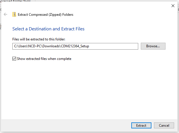
After downloading the file, navigate to your download folder. Right-click on the compressed folder and select “Extract All…”. Choose the desired extraction location and click the “Extract” button.
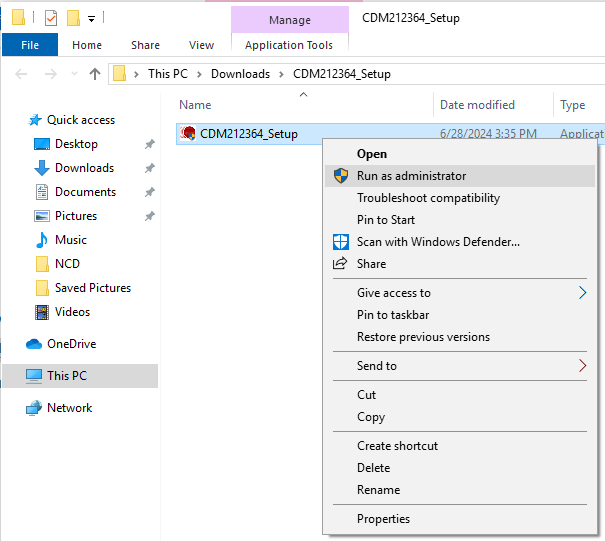
After extracting the folder, open it and right-click on the installer file. Then, select the “Run as administrator” option:
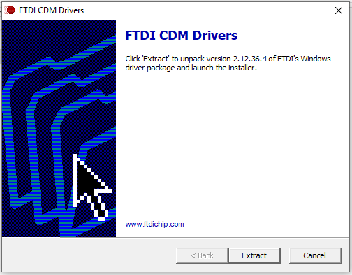
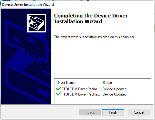
Finally follow the driver installation steps:
After completing the installation process, verify if your PC recognizes the Industrial IoT Wireless to USB Modem as a COM/Serial port when you connect it.
Configuring NCD Nodes
To receive data from sensors sent through the Industrial IoT Wireless to USB Modem or Industrial IoT Wireless to Ethernet Modem within Node-RED, you need to configure the Wireless Gateway and Wireless Device nodes. Here’s a step-by-step guide to perform this configuration.
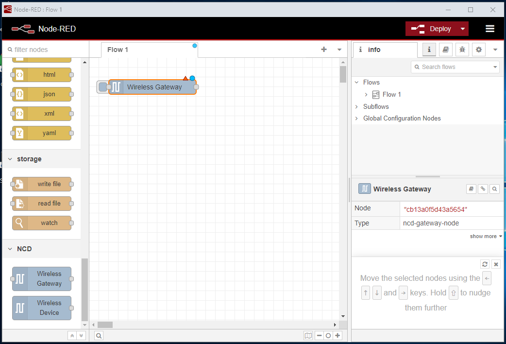
You will need to drag the Wireless Gateway node from the node palette to the workspace (the white central area with rectangles). To drag the node, left-click on it and hold the button down while moving the cursor to the workspace. Release the left mouse button to position the node.
When you place the node in the workspace, you will notice a red triangle in the top right corner of the node. This indicates that the node is not configured correctly. In other words, it requires configuration before you can use its functions. You will see something like the following:
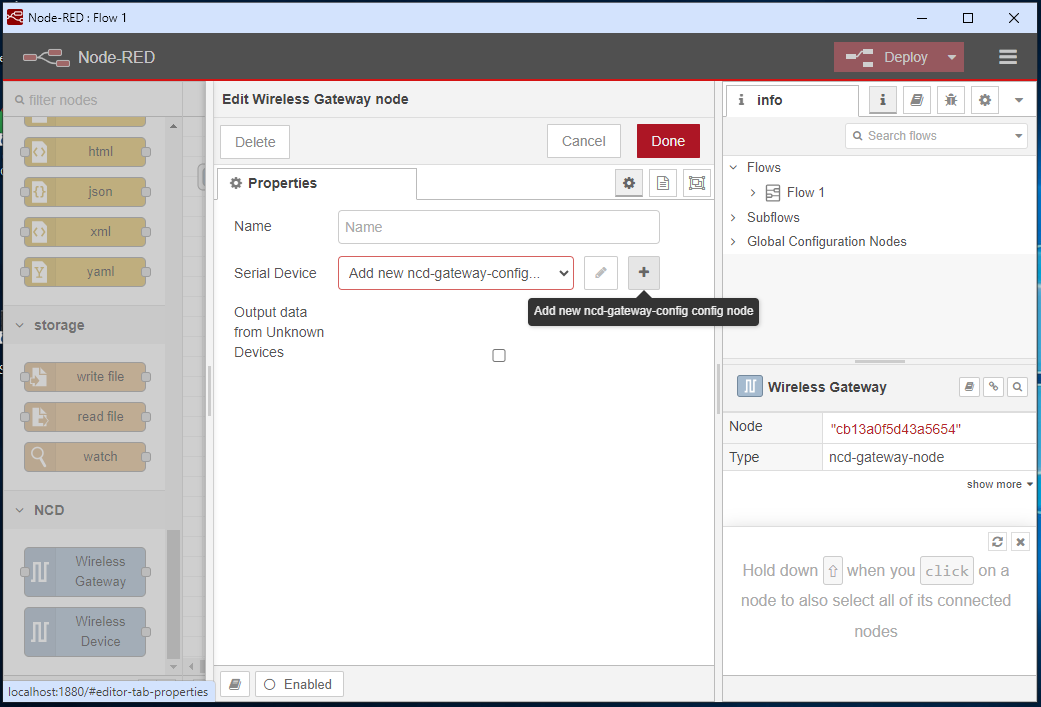
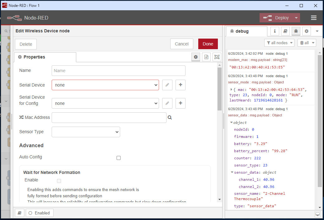
We will now proceed to configure the node. To do this, double-click on the node to open its properties window. You will notice that it has a “Name” property and a text input box that you can use to name the node (this property is optional, meaning that it is not mandatory to assign a name to the node in order to work with it). Next, we have the “Serial Device” property, where we currently have no configuration. To add a configuration, click on the “Add new ncd-gateway-config config node” button, as shown in the following image:
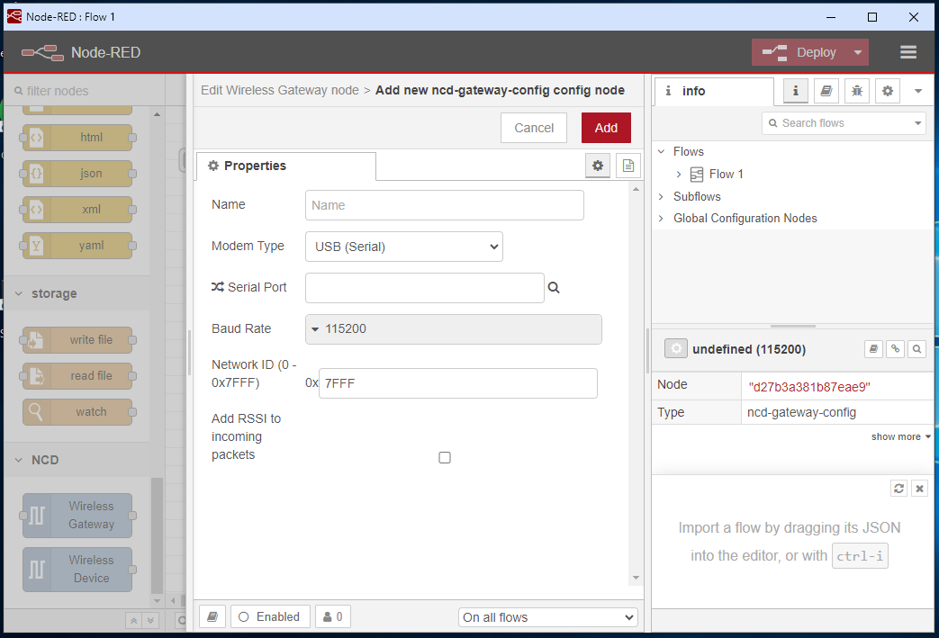
This action opens a new configuration window where we will set some properties. You will notice that it has a new “Name” property where you can assign a name or identifier to this configuration (again, this is an optional property). Next, we have the “Modem Type” property and a dropdown menu. This property allows you to select the type of Industrial IoT Wireless Modem you are using. The options are USB (Serial) or TCP (Ethernet/Network). For this example, we will continue with the USB (Serial) option. However, if you are configuring the Industrial IoT Wireless to Ethernet Modem, the steps are the same, except that you should select the “TCP (Ethernet/Network)” option for the “Modem Type” property. For the “TCP Port” property, you can use the default option “2101”, and for the “IP Address” property, you should enter the IP address of the Ethernet Modem.
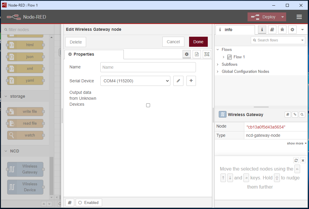
You should click on the “magnifying glass” icon, it will automatically show the available COM ports. In this case, you should select the COM port that corresponds to the connected USB Modem. (If for some reason you have more than one COM port on your PC, an easy way to identify the COM port number is to use the “Windows Device Manager” window. Then, disconnect the modem and observe the port that is disconnected. Reconnect it again and identify the COM number that appears.) You should select the COM port corresponding to the USB Modem. Once you have selected the COM port you must press the “Add” button:
Click to expand
Click to expand
NoteIf you don't see the serial port that could mean your computer is blocking the serial port and you will need to contact your IT dept to help you with this. Check following:
Make Sure the Serial port is not open in any other application.
Make Sure Correct FTDI drivers are installed.
Is the Serial port number visible in Windows Device Manger.
Automatically return to the “Edit Wireless Gateway node” window, you must press the “Done” button.
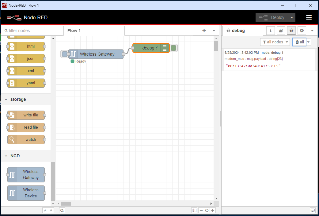
To observe the sensor data received by the Wireless Gateway node through the USB-COM port inside Node-RED in a simple way, we use the “Debug” node. This node allows us to observe the data inside a dedicated tab within the Node-RED editor. To do this, we connect the output of the “Wireless Gateway” node to the input of a “Debug” node that we added. Then, inside the sidebar, click on the “Debug messages” icon as shown in the following images:
Click to expand
Click to expand
You will see the message field inside the “debug” tab. Then, click on the “Deploy” button to apply and save the changes made in the flow. When you do this, you will see a green box just below the “Wireless Gateway” node indicating that the node is trying to establish a connection with the USB Modem using the established USB serial port (COM) settings.
Click to expand
Click to expand
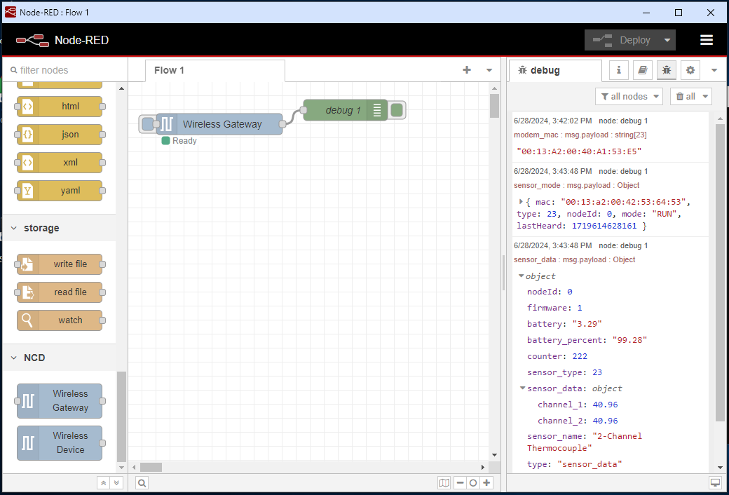
Once the connection between the USB Modem and the “Wireless Gateway” node within Node-RED is established, you’ll see a green box with the “Ready” label indicating a successful connection. Additionally, you’ll see in the debug window that the “Wireless Gateway” node receives the USB Modem’s MAC address as soon as the connection is established. This information is displayed in the message field of the debug window, as shown in the following image:
Potential Issue Following Deployment
During the initial startup of the Wireless Gateway node in Node-RED, you may encounter the following error upon deployment: “TypeError: Cannot read properties of undefined (reading ‘on’)“. To resolve this issue, close the Node-RED interface, restart Node-RED, and execute the run file again.
Click to expand
The next step is to turn on the NCD sensor so that it starts transmitting data and the Modem receives and displays the data within the Node-RED. For this example we use the sensor “2 – Channel Thermocouple”, when the sensor is turned on, it establishes connection with the Modem, then it sends a “RUN” packet and then a data packet, this data packet contains the complete sensor information; nodeId, current Firmware version in the sensor, battery voltage, packet counter, sensor type, sensor data (sensor variable values), sensor name, among other data, as shown in the following image:
Adding Wireless Device node
The NCD library also includes a “Wireless Device” node. This node allows you to filter the sensor data received by the modem. You can filter based on the sensor’s MAC address or type. Additionally, the node can be used dynamically to configure NCD sensors wirelessly when they are put into configuration mode.
NoteIt is entirely possible to develop a project within Node-RED using only the Wireless Gateway node. This setup allows you to receive messages from sensors and build a complete flow by connecting additional nodes to the Wireless Gateway node's output. You can filter messages, forward them to cloud services via protocols like MQTT, OPC-UA, or HTTP, store data in local or cloud databases, or trigger alerts through email, among other functionalities.
In this section, we will demonstrate how to add and use the Wireless Device node, along with its basic configurations. For more advanced options, refer to the user manual of the specific NCD sensor to explore its detailed configuration settings.
NCD Sensor ConfigurationIf you are interested in learning how to use the Wireless Device Node to configure parameters for NCD sensors, we recommend exploring the following article. It provides detailed guidance to help you get started:
Now that we’ve received sensor data in Node-RED, the next step is to use the ‘Wireless Device’ node to manage, configure, and filter the data and properties. Drag this node to your workspace to begin configuration.
Click to expand
Click to expand
Double-click on the “Wireless Device” node to open its properties window. You’ll see the “Name” property first, which is still optional as mentioned before. This property allows you to assign an identifier to the node, making it easier to differentiate it from others in your workspace.
Next, you’ll find the “Serial Device” and “Serial Device for Config” properties. Assigning values to these properties isn’t necessary for creating a new configuration. Instead, we’ll use the same configuration as the one used in the “Wireless Gateway” node (these configurations are known as “Configuration nodes”). Since it’s an existing configuration, click the dropdown arrow to see the available options and select the configuration we created in the previous step.
This process is exemplified in the following images:
Click to expand
Click to expand
This next step is optional and allows you to filter data from a specific sensor using its MAC address. Within the “MAC Address” property, you’ll find a text entry box and a magnifying glass icon on the right. Clicking the icon will display the MAC addresses of devices that have already connected to the USB modem and sent data. Select the desired MAC address from this list.
NoteWhen you select and assign a value to the "MAC Address" property, the node automatically identifies the sensor type associated with that address and populates it as a parameter in the "Sensor Type" property. This process is shown in the following images.
Click to expand
Click to expand
Next, click the “Done” button. Then, connect a new “Debug” node to the output of the “Wireless Device” node. This allows you to view the received and filtered messages from the chosen sensor. You can clear any previously received messages using the “Clear messages” button in the “Debug” tab, as shown in the following images:
Click to expand
Click to expand
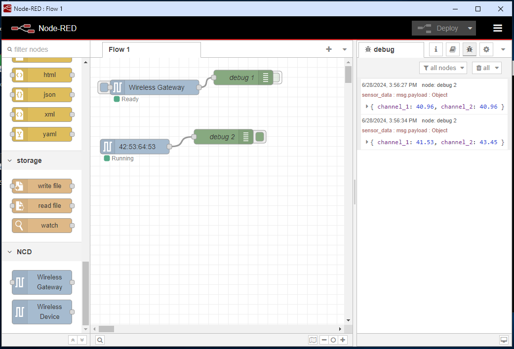
You can disable the “Debug” node connected to the “Wireless Gateway” node. This will hide data received through that node and only display messages received by the newly added “Debug 2” node, which shows data filtered by the “Wireless Device” node. Finally, click the “Deploy” button again to save and apply these changes:
Finally, when you deploy the flow, the “Wireless Gateway” node will establish a connection with the USB modem. Once a new sensor reading is received, it will be filtered by the “Wireless Device” node. This filtered data will then be sent to the “Debug 2” node, where you can view it as shown in the following image:
We also have a video tutorial available, which you can use as a resource for a step-by-step guide to this configuration: