Instructions and Testing
Relay Controller Configuration
- Safely disconnect all power to the Relay Controller and ensure no LEDs remain lit.
- Remove the WiFi Module in place
- Place the USB module in the XBee socket (double check that all of the legs are in place)
- Connect the USB to your computer
- Apply power back to the relay controller
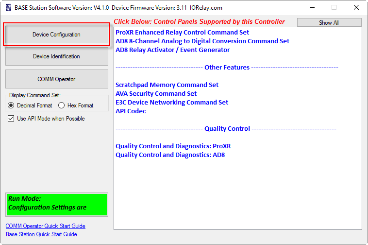
- Run Base Station and connect to the USB controller using baud rate 115200 (ncd.io/start)
- Select Device Configuration in the top left
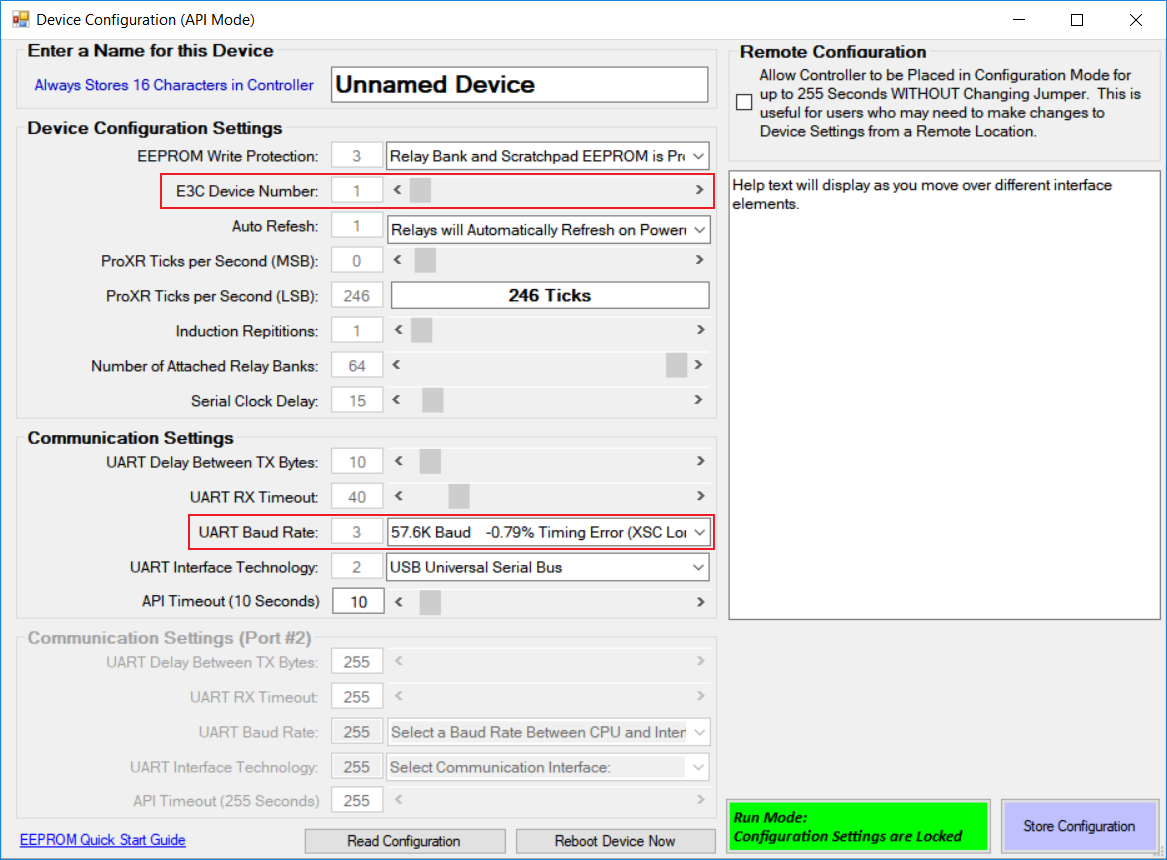
- Set the E3C field value to a non-zero value that will be unique to this RS-485 chain.
- Set the Baud Rate field value to 57.6k as shown below
- Exit out of Base Station
- Power down the board and remove the USB Module
- Place the RS-485 (PR-37-9) into the XBee socket and insure the pins are aligned
- Connect the RS-485 to the RS-485 wiring coming out of the Ethernet to RS-485 Bridge
- Refer to https://ncd.io/rs-485-network-quick-start-guide/ for wiring diagrams
- Place the Jumpers on the RS-485 modules as outlined in the guide linked above
- Power up the board
- Open a TCP socket to the Ethernet to RS-485 Bridge (default port 2101)
- Send the command 254 252 x as bytes in the NCD API where x is the E3C number of the board.
- The NCD API is outlined at https://ncd.io/api-codec-quick-start-guide/
- Send the command 254 33 wrapped in the NCD API.
- The device should respond 170 01 85 00
Configure the Ethernet to RS-485 Adapter
The ethernet module used on this board is a highly configurable device. We are going to be covering the settings necessary to communicate to the RS-485 network. Full guide is available at https://ncd.io/lantronix-xport-communications-module-quick-start-guide/.
- Connect the the Adapter to your Ethernet Network and power up the Adapter
- Go the the IP address of the Ethernet module in your browser
- Base Station can be used to quickly find this device if no static IP address is allocated. See ethernet guide referenced above
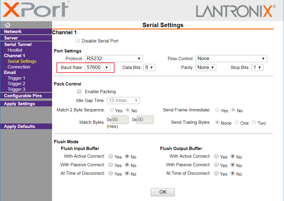
- Select “Serial Settings” on the left
- Change the “Baud Rate” field under “Port Settings” to 57600
- Click the “OK” button at the bottom
- Click “Apply Settings” on the left
- Once the configuration is complete as indicated on the web browser, power cycle the Ethernet to RS-485 Adapter
Controlling the Device
Software will need to target individual IP addresses via a TCP socket to control a specific RS-485 network.
Individual devices on the RS-485 network can be targeted using the command 254 252 x where x is the E3C number assigned to the device. This command must be wrapped in the NCD API as outlined https://ncd.io/api-codec-quick-start-guide/.
Once targeted the controller will respond to the basic ProXR command set: https://ncd.io/proxr-quick-start-guide/