Introduction
This section will give you step by step instructions on how to access your controller using DHCP Addressing. If you would like to use a static IP Address that will be covered further on in the guide. This section assumes that you have a network with a windows based machine on it running NCD Base Station. Connection to NCD Lantronix devices can be made in two ways, TCP Socket connection or a Virtual Com Port. Both are covered individually in the following pages.
Communication Setup
TCP Socket Setup
- Remove the Ethernet Relay Controller from its packaging and connect it to the same network as the computer that you are going to use to control it (note: this network must support DHCP, most standard routers do) a network switch cannot be used until a static IP is stored in the device; this is covered later in the guide.
- Once the Ethernet cable has been attached to the Ethernet module and the Ethernet network, you can apply power to the board using the barrel connector. Please ensure that this is a 12vDC regulated power supply.
- Download NDC Base Station onto your windows based machine and install it. The software can be found at //ncd.io/start
- Once Base Station has been installed run it and the Ethernet device should show up in the list titled “Discovered Network Devices”, this can take a few seconds.
- If you have more than one of our network devices on you network you will need to match the MAC Address printed on top of the intended module. See the section title “Finding the Mac Address” for more information on how to find the MAC Address.
- If this device does not show up in this list see the section of this guide title Base Station “Does Not Discover the Module”
- Select the intended device from this list and select OK down at the bottom of this window.
- Once this is done the control interface that you will be shown is different depending on which series of controller the Ethernet Module is installed on. This is a good place to start getting familiar with all of the features of your controller and what commands it takes. For each item you select from the list you will see a MORE button in the top right corner. If you select this button you can see the commands that are being sent to the controller as well as a link to a Quick Start Guide specifically for those commands or that technology.
Virtual Com Port Setup
- Remove the Ethernet Relay Controller from its packaging and connect it to the same network as the computer that you are going to use to control it (note: this network must support DHCP, most standard routers do) a network switch cannot be used until a static IP is stored in the device, this is covered later in the guide.
- Once the Ethernet cable has been attached to the Ethernet module and the Ethernet network, you can apply power to the board using the barrel connector. Please ensure that this is a 12vDC regulated power supply.
- Download NCD Base Station onto your windows based machine and install it. The software can be found at //ncd.io/start.
- Ensure the controller and computer you are using are connected to your LAN
- Download install and Launch the Lantronix Secure SCPR Manager here: http://www.lantronix.com/sftw/scpr-dl.php (Download requires registration but the application is free.) After completing the registration click the http link to the right of SCPR Setup Application for Windows GUI (See figure 3—1)

Figure 2-1 - Once launched you should see the Secure CPR Manager Window this application will allow you to create a virtual com port directed to your Lantronix Ethernet device. You may press F1 at any time to access the applications help menu.
- Click the Add/Remove button in the upper right corner to add a new virtual com port. A window will appear.
- All Com ports on your computer will be displayed. Click the check box next to the first available Com port then click ok. (Note you may click the checkbox next to any available com port).
- You will now see the com port listed in red under the list of com ports. Double click the com port to edit it.
- You will now see all settings for the com port. We recommend leaving all default settings initially, you may change them later if needed. Scroll down in the com port settings until you see the table with Service Host and TCP Port. A text box under Host and TCP Port should be available.
- Click the Search For Devices button at the top of the window. You should see the Lantronix device appear in the Device List after a few seconds. Here the IP address and TCP port number will be listed. Type the IP address into the Host text box and the TCP port number into the TCP Port text box.
- Click the Save Button above to save this new virtual com port. The Com port in the list should turn black and should be ready for use.
- Close the Secure CPR Manager. Launch NCD Base Station.
- In Base Station select the newly created com port from the com port list, ensure 115200 baud is selected as the baud rate, then click ok.
- The software should connect to the controller and display a list of sample applications you can now use to test your controller.
Functionality and Features
TCP/IP Communications
The main method of communication to our Ethernet modules is a standard TCP Socket. This communication protocol makes use of Network Sockets to create point to point tunnels that data can flow through bi-directionally. In this way the computer that is controlling the relay can send commands and shortly thereafter receive the response through the same Socket.
In most programming languages all you have to do to open a socket is import the appropriate plug-in, build the socket object, and connect the socket using the IP Address and Port Number of the target device. Once the request for connection reaches the target device via the IP Address as a physical address of an office building and the port number as the number of the particular off you are trying to reach.
Base Station software will adapt this window for your particular model of controller. Click on ProXR Advanced Relay Control Command Set
Finding the MAC Address
You can find the MAC Address of the module in one of two ways. The first option is to look on the top of the Ethernet Module itself where it is printed.
The second way is to run NCD Base Station on a computer that is on the same network as the Ethernet Module. This method will not work if there are multiple network devices on the same network.

DHCP and Static IP Addresses
This module supports both DHCP and static IP Addressing. For communications reliability, especially via Remote Access, we recommend using a Static IP Address when you feel comfortable doing so. This will ensure that the device will always be where you expect it to be when you try to connect to it.
DHCP
DHCP stands for Dynamic Host Configuration Protocol and basically means that your router will assign the first available IP Address in the list of IP Addresses and assign that to your device. While this technology makes network devices very easy to use and locate it is not as reliable in that certain circumstances will cause the IP Address it assigns to change or have two devices on the same IP Address. This should not be used in most relay control applications. DHCP is what these modules ship out as. In this way we can ensure that the module will successfully connect to any network regardless of IP Range.
Static IP Address
This technology is the antithesis of DHCP in that it is manually set and does not dynamically change without some kind direct action. The downside of this method is that, if done incorrectly, can make the module unreachable through any standard means. This usually happens when an IP Address is statically set to an IP Address outside of the range of the router, or another device on the network obtains this IP address via DHCP. If this happens, see the section of this guide titled “The Static IP Address is Incorrect”. This is the preferred and more reliable way to handle network IP Address allocation. For improved reliability the IP Address assigned to this Module should be reserved on your router.
To store a Static IP address to the controller
- Open your favorite web browser and enter the controller’s IP address into the URL, then click Enter.
- When asked for Username and Password click enter as by default the username and password are not enabled.
- On the left menu navigation click Network.
- Here you will see Obtain IP address automatically is selected which is what we recommend for most applications.
- To set a Static IP address into your module click the radio button labeled Use the following IP configuration:
- Enter your required settings. (Examples shown below)
![]()
Once you settings are entered click the OK button below. - Click Apply Settings in the left navigation menu to ensure your settings are stored to the module.
- Close your web browser, then power cycle your controller to ensure the device is now using the entered Static IP address. You may use Base Station to discover the device if needed.

Remote Access and Port Forwarding
Remote Access
By remote access, we mean the ability to access this module and control its relays from anywhere in the world. This is only possible if both the module and the computer/device trying to control it are connected to the internet. The only thing required to do this, outside of internet access, is Port Forwarding on your router.
We have made remote access simple by giving you a gateway to get the External IP Address and port number of the device. In your favorite browser simply enter link.signalswitch.com/MacAddress where MacAddress is the MAC Address of the device. Refer to the section titled “Finding the MAC Address” for more information on finding the MAC address of the Module. A page will be returned to you with the IP Address and the Port Number in the format or 207.129.124.0:2101 (the numbers it displays to you will be different.). You can either use this information using Base Station or you can use it with your own custom application (it is suggested that you query this every time you connect to the board for a custom application because most External IP Addresses rotate as a security precaution.
Please note: Any attempt at remote access while still on the same network as the device you are trying to control will cause a communication error and will not be possible. Instead use LAN Communications.
Advanced Remote Access
If you have multiple network devices on the same network then you will be required to change the TCP Listening Socket of them in order to have differentiated Remote Ports. Without doing this all of your network devices will report the same Remote Port to link.signalswitch. Your router, on the other hand, can only forward Port 2101 to one device at any given time. If different ports are assigned to each device using Base Station then link.signalswitch will report a different Remote Port for each device and your router can forward each incoming request on the specified port to he intended device.
Port Forwarding
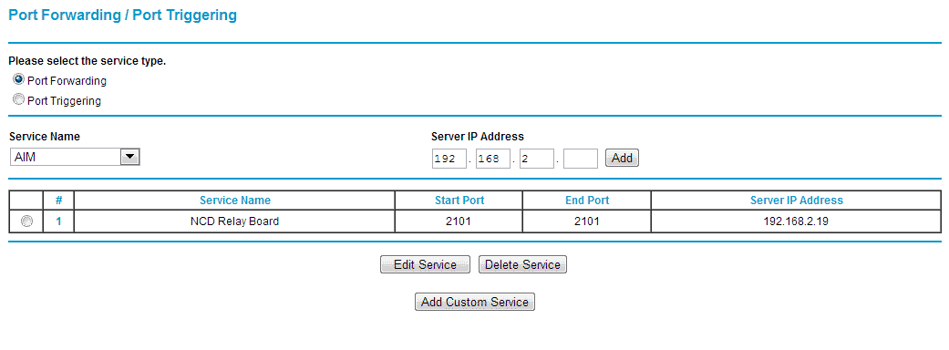
Port Forwarding is a protocol used by your router to allow incoming requests for connections to get through it to a specific device on a specific port. Here is an example of how it works. In this example your router has been setup to forward incoming requests for port 2101 to the device at the IP Address 192.168.2.19 on port 2101. This means that any time any device tries to access this Port on your External IP Address (External IP Address are how everyone outside of your network can locate your network, check ipchicken.com for your external IP Address) then the router will see the request and automatically forward the request to the device at the IP Address of 192.168.2.19 on port 2101. If this Port Forwarding rule was not in place and a request came in one port 2101 then the router would not know which device it was supposed to forward this to on its own network. In this case the request for connection would be denied.
Clear Jumper
There is a two pin jumper connection on the Ethernet Module that is used to set your Ethernet Module back to Factory defaults. This jumper must be disconnected from the board if you wish to use this module. This is used in case there has been a Static IP Address assigned to it that is outside of the range of the Router’s IP Address which makes the module unreachable. To reset back to Factory Defaults simply unplug power front the board, attach a jumper to the jumper connection title CLEAR (the PRG/RUN or UP/DOWN can be temporarily used if necessary), and reapply power to the board. Wait about ten seconds with power attached to the board (Orange LEDs will flash on the module) and then unplug power and remove the jumper (replace the PRG/RUN or UP/DOWN jumper if used). The next time that power is applied to the board it will be in complete factory settings.
NCD Default Settings
- Ensure the Lantronix Controller and your computer are connected to the same LAN.
- Check your network’s attached devices to find the controllers IP address.
- Enter that IP address into your favorite browser to bring up the controller’s web interface.
- When asked for a user name and password just press enter (by default there is no user name or password for the web interface).
- Click the Serial Settings on the left menu navigation.
- Under Port settings change the baud rate from 9600 to 115200. Then click OK below.
- Click Connection from left menu navigation.
- Under Endpoint Configuration change the Local Port number to any Port number you would like the controller to listen on then click OK below. 2101 is our default port number and we recommend using it.
- Click Apply Settings from the left menu navigation to ensure all settings are saved to the module.
- You may now close your web browser and launch the NCD Base Station Software.
- In Base Station click the More button in the upper right corner to expand the window showing more options.
- Click the Lanx Ethernet Setup Button which appears below.
- In the window that appears enter the controllers IP address in the text box labeled Current IP address, then click the Configure Module button below to set the module back to NCD Default Settings.
- Now you may reopen Base Station and it should discover the device properly.
Switch/Direct Connection
By default Lantronix XPort Pro modules are in DHCP mode meaning they must connect to a DHCP server in order to obtain an IP address. If your device will be connected to a switch or directly to a computer where DHCP is not available you must store a static IP address to the device using the instructions in this guide. Note that storing a Static IP address to the controller will require initial connection to a DHCP Router; it is absolutely not possible without it. Once the controller has a Static IP address you can connect it to a network switch and make connection to it via that static IP. If you wish to connect the device directly to a computer you will need a cross over Ethernet cable.
Virtual COM Port
A Virtual COM Port is a software layer that allows you to communicate to a network device as if it were a serial device connected directly to your computer. See Virtual Com Port under Quick Start for information on configuring a virtual com port to your Lantronix Ethernet device.
UDP Broadcasts
This module makes use of UDP Broadcasts to allow us to find the device both over a LAN connection and over the Internet via link.signalswitch.com. If you would like more information on this please contact us.
Troubleshooting Your Module
Base Station Does Not Discover the Module
Please make sure that you have the latest version of Base Station.
If you are running the latest version of Base Station then this error is caused by either the Module being reset to factory defaults using the clear jumper or the module not being on the same network as the computer Base Station is being used on.
To check and make sure it is on the same network as Base Station log in to your router via the computer being used for Base Station and check the list of attached devices for MAC Address of your module. If you do not know the MAC Address of the module refer to the section title “Finding the MAC Address”. Windows Firewall, McAffee, and many other antivirus software may block incoming UDP broadcasts that are used to locate this device over the network. Please disable this firewall temporarily to ascertain whether or not this is the problem.
If this device is listed here then the device is on the same network and the problem is with module itself. In this case you should set the module back to factory defaults to ensure no incorrect settings are in the module. Please see NCD Default Settings in this guide. This should fix this problem. If this process does not fix your problem please contact us.
Signalswitch States “Device’ information is not found!”
This problem can be caused by lack of internet access on the network or by a firewall on your network that is stopping the Ethernet Module’s broadcast to link.signalswitch. This broadcast is required to give link.signalswitch the necessary information it needs to report back to you. If a computer on the same network as the Ethernet Device has internet access then you will need to contact your Network Administrator about possible firewalls or the manufacturer of your router about any firewalls that may be active on your router. UDP Broadcasts over port 13000 will need to be allowed to pass the through the firewall for link.signalswitch to receive the necessary information.
Controller Does Not Respond
If the controller does not respond through your custom application you should try connecting to it using Base Station (Note: Base Station only communicates over port 2101). If you cannot communicate to it using base station you should reset the module back to factory defaults and reconfigure it using NCD Base Station. See the section titled “Clear Jumper” for more instructions on this. If the module has been successfully reconfigured and base station can connect to it, but there is still no response contact us for support as there may be some defect in the board itself or in the application. For future fulfillment possible reasons it could go bad that we can explain how to fix:
- Wrong Port Number
- Wrong IP (because it may change) use this as a reason to suggest static IP Address
- Board has incorrect power
- Induction issues
- Incorrect Baud Rate
- Something wrong with board, check corresponding quick start guides
Controller Does Not Respond Reliably
If the controller seems to work correctly for a while and then seem to randomly drop communications the problem is most likely with using inductive loads. An inductive load is any load that causes power spikes/surges to go through the relay any time that it is activated or during operation. These loads include motors, transformers, and just about anything that cause movement. It is possible for these surges to reach the microprocessor, thus causing the failure of communications as it shuts down to protect itself. The use of capacitors is suggested to reduce the effects of this. These operate by absorbing the spikes in power and slowly releasing the stored up energy safely back into the system. For more information on the use of induction suppression see our full article on Induction Suppression.
The Static IP Address is Incorrect
If the static IP Address was incorrectly set to something that the network still has access to, simply change the set static IP Address of the module. If the static IP Address was incorrectly set to something outside of the range of the network’s IP Addresses then you will need to perform a factory reset and reconfiguration. See the section titled “Clear Jumper”.
The Web Interface Asks for a Password
By default the web interface will ask you for a password even if there is none set. IF none has been set, simply hit enter or select OK. If this does not get you into the web interface then you will need to do a factory reset and reconfiguration of the module. For more information please see the section titled “Clear Jumper”.
Nomenclature
IP Address
Internet Protocol Address – The standard way in which computers are addressed over network communication. An IP Address can be through of as a digital street address. Despite the work internet it is used even in networks that are offline.
Internal IP Address
This IP Address is used to locate devices on the same network or sub-networks. The reason this is called an “Internal” IP Address is because these locations will ONLY work when on the same network. If used to attempt access from external network the attempt will fail.
External IP Address
This IP Address is used to locate devices on external networks. The reason this is called an “External” IP Address is because this is the address that any external network can find your network at, but your network cannot speak to devices on itself in this manner.
Port Number
Port Numbers are basically inlets into a network or device that allow access to its internals from remote communications. They can be thought of as doorways into a specific device which can be opened or closed depending on the needs of the application.
Port Forwarding
A protocol that routers use to forward incoming internet requests to the correct device on the correct port.
MAC Address
Media Access Control Address – A Unique Identifier assigned to network interfaces (Ethernet jacks on a computer, WiFi Adapters, etc.). MAC addresses are used to differentiate devices from each other.
Network Socket
A Network Socket is a virtual tunnel that allows data transmission between two devices. When connecting a Network Socket and IP Address and a Port Number must be given for proper targeting. Numerous protocols can be used over a Network Socket. However, the one used to control our Ethernet Devices is the TCP Protocol.
TCP/IP Communications
This is a communication protocol that uses Network Sockets to transfer data between devices Bi-directionally. These are generally called Stream Sockets as data can flow between them freely. It can be thought of as a phone call between two devices.