In industrial environments, Programmable Logic Controllers (PLCs) and Supervisory Control and Data Acquisition (SCADA) systems rely heavily on standard, wired communication protocols like Modbus TCP. However, modern industrial sensors—such as NCD sensors—often utilize advanced, power-efficient wireless protocols like DigiMesh to maximize range and battery life. This creates a fundamental communication barrier: your PLC cannot natively “talk” to your wireless sensors.
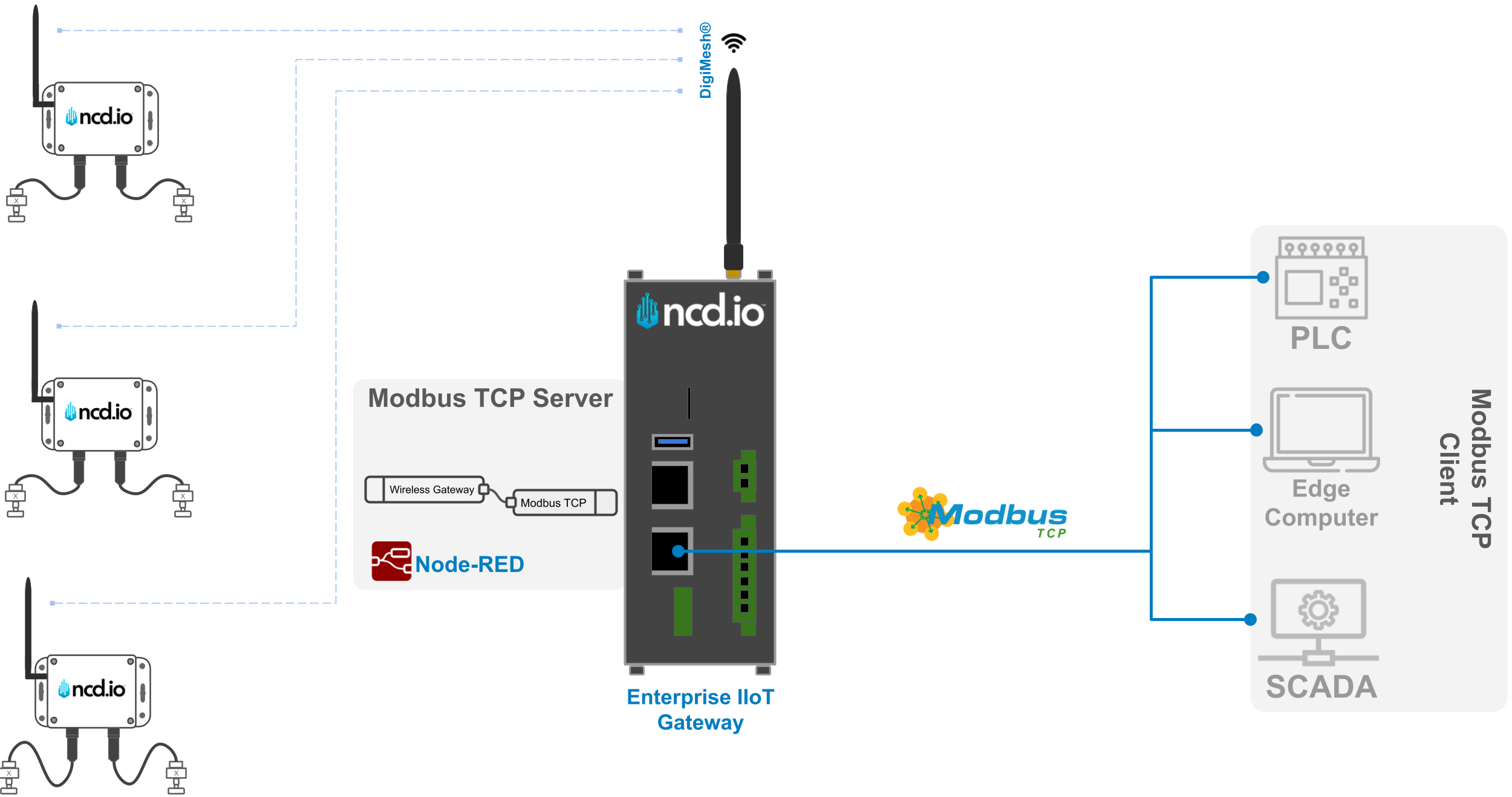
This guide solves that problem by using the NCD Enterprise IIoT Gateway as a powerful protocol bridge. By leveraging Node-RED on the gateway, you can seamlessly receive wireless DigiMesh sensor data, decode it, and host a local Modbus TCP server. This allows any standard Modbus TCP client (like a legacy PLC or Edge PC) to easily read the wireless sensor data from designated registers over a simple direct Ethernet connection.
The Enterprise IIoT Gateway runs Node-RED, which natively supports a wide range of communication protocols, making it a highly versatile tool for industrial and IoT applications. Common supported protocols include:
MQTT: For lightweight, reliable, and scalable messaging.
HTTP/HTTPS: For web-based communication and RESTful APIs. Modbus (TCP/RTU): For communication with legacy and modern industrial devices like PLCs.
OPC UA: For standard integration into industrial automation systems. WebSockets: For real-time, bidirectional communication.
Serial: For communicating with legacy serial hardware.
Node-RED’s extensive open-source library also allows for the integration of many other protocols, making it adaptable to virtually any use case.
Important!Since the Enterprise IIoT Gateway is built on a Linux-based architecture, please note that privileged port restrictions prevent non-root applications from binding to ports below 1024. Therefore, we recommend avoiding the default Port 502 for Modbus TCP communications to prevent socket binding errors. It is best practice to utilize a non-privileged port.
ImportantWhile the gateway supports protocols like Modbus TCP/RTU, if your PLC or SCADA system supports MQTT, we highly recommend using MQTT over Modbus TCP. MQTT is generally more straightforward, scalable, and better suited for modern IoT architectures.
DisclaimerFor this guide, we use the node-red-contrib-modbus open-source, third-party library. NCD does not support this library directly, and standard open-source bugs or limitations may apply.
Best Approach: Modbus Server on the Gateway or the PLC?
When using the Enterprise IIoT Gateway as an intermediary to collect data from NCD wireless sensors and expose it to a control system, Node-RED is an excellent choice for local processing and decoding.
Architectural Strengths:
Protocol Bridging: The gateway acts as a bridge between the NCD sensors (DigiMesh) and the PLC (Ethernet/Modbus TCP), a standard IIoT practice for handling mixed protocols.
Edge Computing: Running Node-RED on the gateway allows for local data processing, decoding, and buffering, which significantly reduces the processing load on the PLC or Edge PC.
Efficiency: Using Modbus TCP over a local Ethernet network ensures low latency and high reliability for short distances.
Why the Gateway Should Act as the Modbus Server
We highly recommend configuring the Gateway as the Modbus TCP Server and your PLC/Edge PC as the Client. Here is the reasoning based on industrial best practices:
Scalability: The gateway centrally collects data from multiple wireless sensors and exposes it. If you need to add more sensors later, you simply configure them on the gateway without having to rewrite complex server logic on the PLC.
Purpose-Built: In IIoT, gateways are designed specifically to convert protocols and act as integration hubs.
Separation of Concerns: A PLC should focus on control logic, not raw data acquisition and protocol translation. As a client, the PLC can simply poll the gateway for data periodically, keeping its logic simple and efficient.
System Isolation: If the gateway loses power or connection, the PLC continues operating with its local data without throwing server-side faults. It also easily supports edge-to-cloud architectures (e.g., adding an MQTT node to the gateway to simultaneously send the same data to the cloud).
Sensors transmit data wirelessly to the Gateway using the DigiMesh protocol.
The Gateway uses the NCD Node-RED library to decode the raw sensor data.
A Modbus TCP server is configured in Node-RED to store the decoded data into specific Modbus registers.
Modbus clients (PLCs/PCs) connect to the gateway via a local Ethernet connection to read those registers.
Procedure
Modbus Package Installation
The most popular package for connecting Modbus devices in Node-RED is node-red-contrib-modbus. It offers extensive configuration options and is well-documented. Like other protocols, fully integrating Modbus requires a well-thought-out schema for how your data will be packed into message objects.
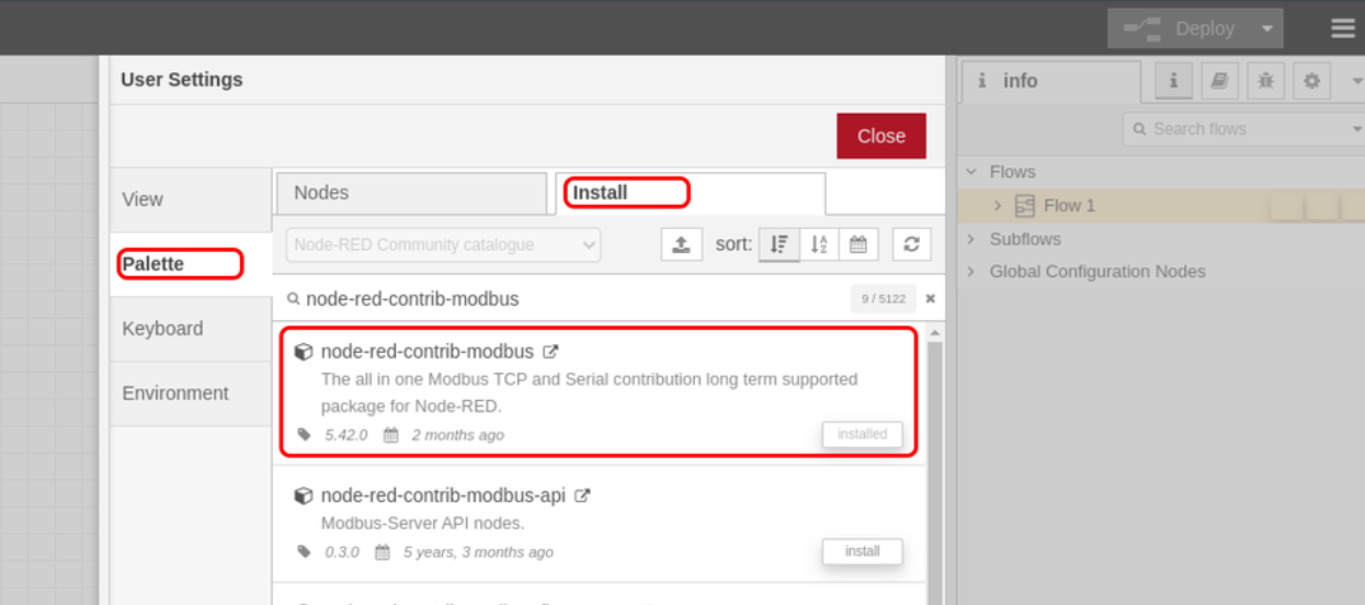
Open your Node-RED interface on the Enterprise IIoT Gateway.
Click the main menu (three horizontal lines) and select Manage Palette.
Go to the Install tab, search for node-red-contrib-modbus, and click Install.
Click to Expand
Importing NCD-Modbus Node
The NCD Modbus node library includes a basic Node-RED node and a flow example. This allows you to link a sensor’s MAC address directly to Modbus TCP start addresses and registers.
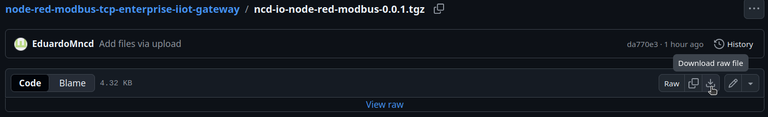
Step 1. Download the raw module file from the NCD GitHub repository: ncd-io-node-red-modbus-0.0.1.tgz.
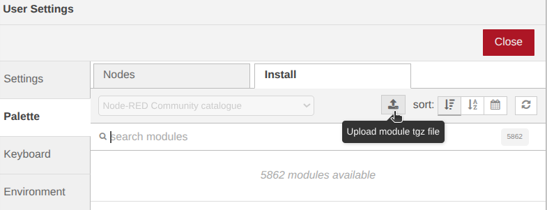
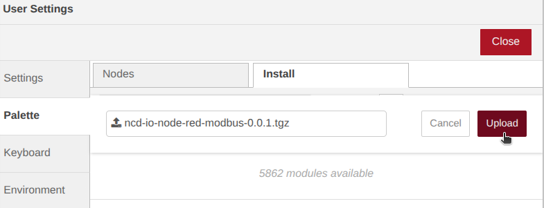
Step 2. In Node-RED, go to Manage Palette -> Install tab and Click the Upload module tgz file button (represented by an up-arrow icon).
Click to Expand
Step 3. Select the .tgz file you downloaded and click Upload. Wait for the installation to complete, then close the menu.
Click to Expand
Importing Flow Example
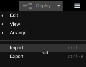
Step 1. Open the Node-RED main menu and click Import.
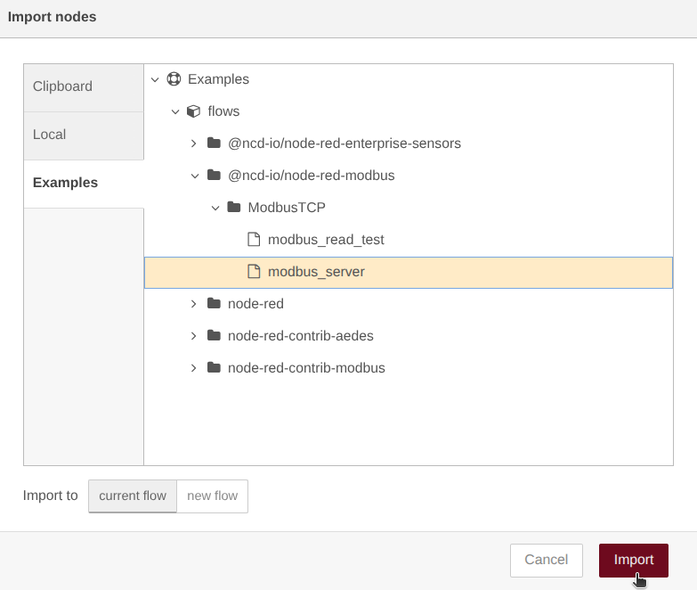
Step 2. Navigate to the Examples menu -> @ncd-io/node-red-modbus -> ModbusTCP. Then select the modbus_server file and click Import.
Click to Expand
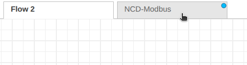
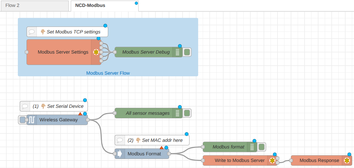
Step 3. You will now see a new tab called NCD-Modbus containing the preconfigured flow.
How the Flow WorksThe flow consists of a Wireless Gateway node to receive the sensor data, connected to an NCD Modbus Format node. The Format node links the sensor's MAC address to a specific Modbus TCP start address. The output is then sent to a "Write to Modbus Server" node, which populates the actual Modbus registers.
Step 4. Configuring the Nodes
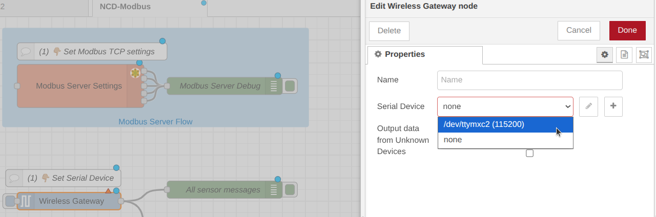
Wireless Gateway Node: Double-click the node and select your configured Serial device from the dropdown menu to ensure it is listening to the internal radio.
Click to Expand
Modbus format node
A custom node to parse NCD sensor data into a sequence of Modbus write commands.
How it works: When a configured sensor transmits data, this node automatically outputs two consecutive Modbus commands to be passed into a standard Modbus Write node:
Sensor Data (FC 16): Writes the array of sensor bytes to the Holding Registers (40000 range).
New Data Flag (FC 5): Writes a 1 (True) to a Single Coil (00000 range) to notify the PLC that new data has arrived.
Note: The PLC should be programmed to read the Coil Flag, process the Holding Registers, and then write a 0 back to the Coil Flag to reset it.
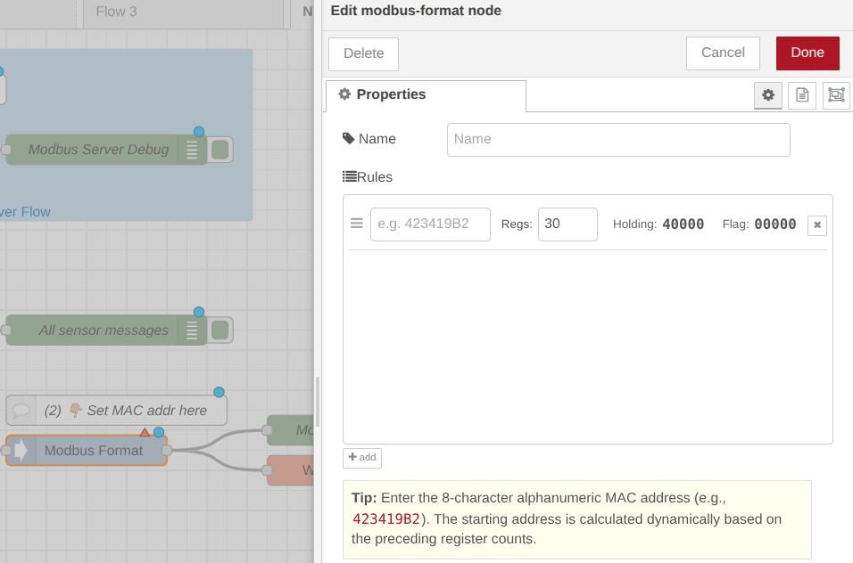
Modbus Format Node: Double-click this custom NCD node. Here, you will enter the last 4 alphanumeric characters of your sensor’s MAC address (found on the physical sticker on the sensor).
Register Allocation: By default, the node reserves 30 Modbus registers per sensor to store data, and dynamically adjusts the Holding Register for subsequent sensors (40000 range).
This node also writes a 1 (True) to a Single Coil (00000 range) to notify the PLC that new data has arrived.
Customization: You can add a new rule for every sensor you deploy. You can also adjust the number of reserved registers. We recommend consulting the API Overview document for your specific sensor to allocate the exact number of required registers.
Click to Expand
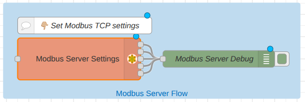
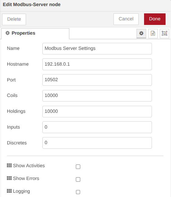
Modbus Server Node (Optional Verification): Double-click the Modbus Server node to verify the settings.
Hostname: Determines which network interface listens for incoming connections.
Port: The communication channel (default is often 10502).
Coils/Holdings/Inputs/Discretes: Defines the available memory spaces for 1-bit and 16-bit data.
ImportantWe highly recommend avoiding the default Port 502 for Modbus TCP communications to prevent socket binding errors. It is best practice to utilize a non-privileged port.
Click to Expand
Click to Expand
Step 5. Deployment and Testing
Click the red Deploy button in the top right corner to save and apply your changes.
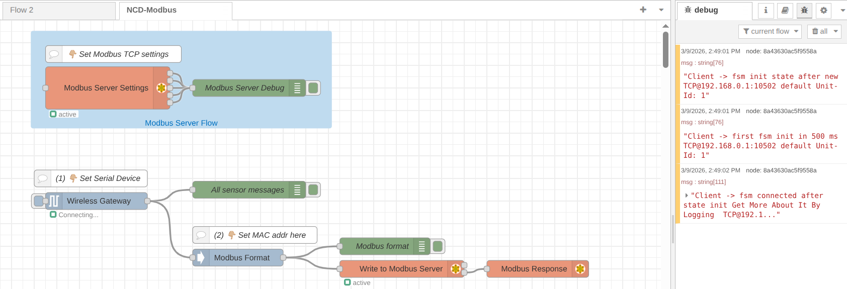
Check the Debug window (the bug icon on the right sidebar). You should see initialization messages indicating the Modbus server is starting.
Click to Expand
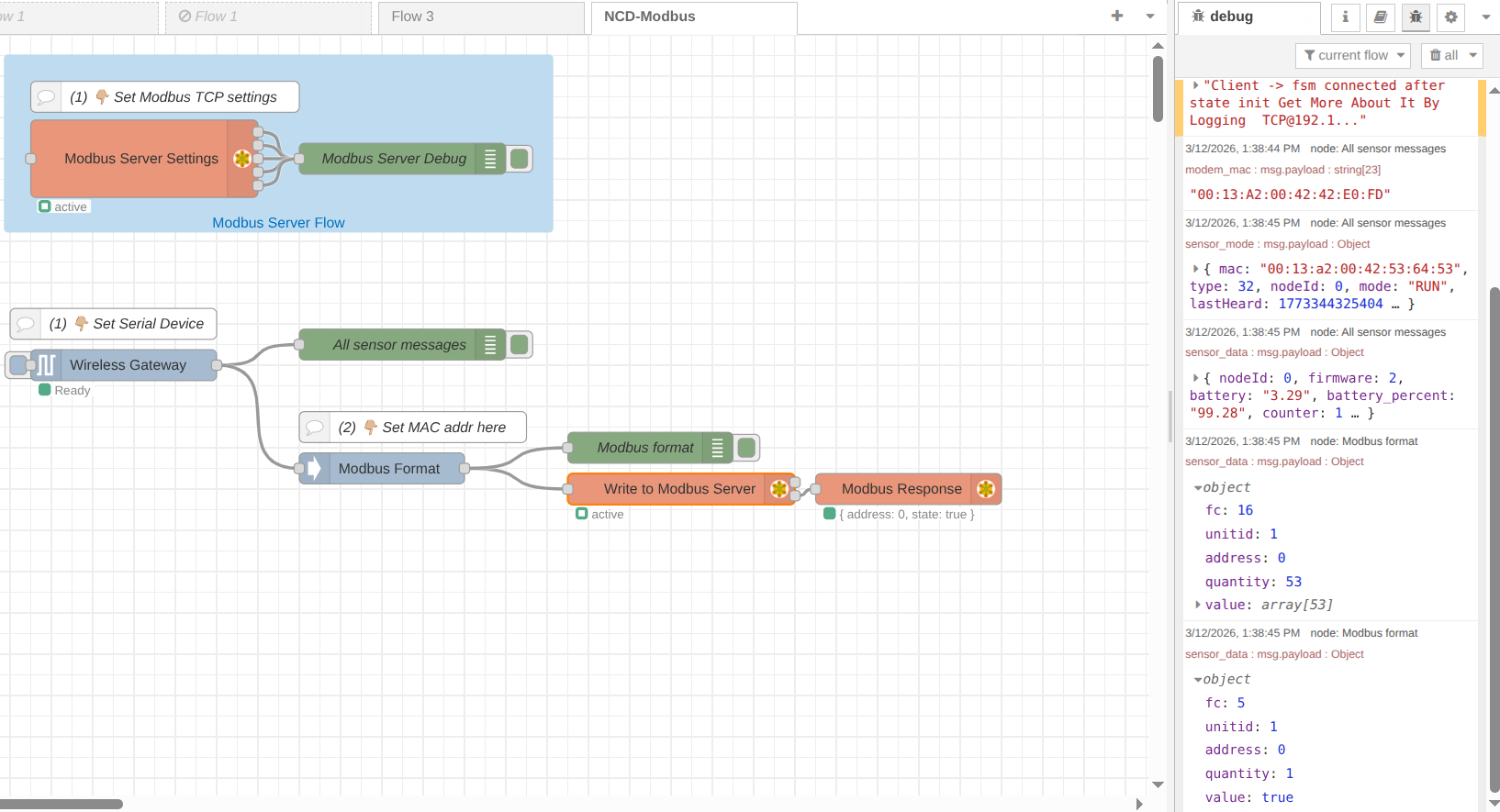
NoteVerify that the Modbus Server node shows an Active status and the Wireless Gateway node shows a Ready status.
Force a Transmission: Press the physical Reset button on your NCD sensor to force it to transmit data immediately.
Click to Expand
Sensor Data (FC 16)
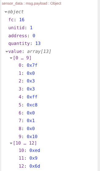
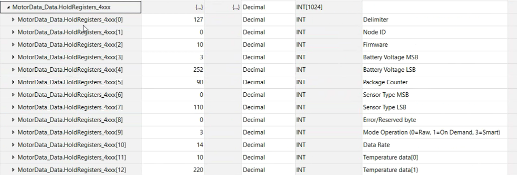
In the Debug window, expand the payload from the Modbus Format debug node. You will see the sensor data API payload broken down into an array of byte values. These are the exact values now residing in your Modbus registers.
This is the API format of the sensor data, you can consult the API Overview document of your sensor in order to identify each byte position in order to read and decode this modbus data from client.
Click to Expand
New Data Flag (FC 5)
The second message is the New Data Flag message, this will writes a 1 (True) to a Single Corresponding Coil (00000 range) to notify the PLC that new data has arrived.
Click to Expand
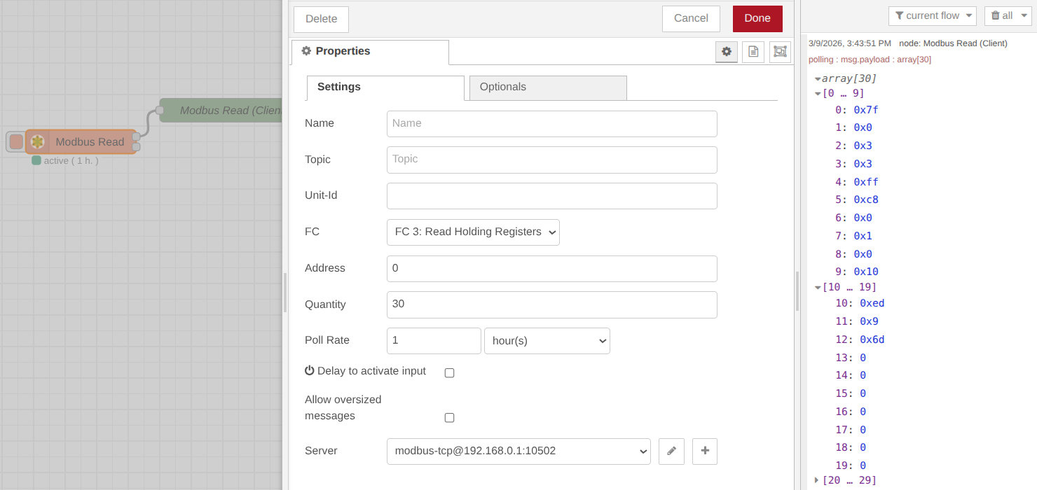
Local Testing Tip
You can drop a Modbus Read node directly into your Node-RED flow, point it at your local server IP (127.0.0.1), and trigger a read to verify the registers are populated correctly before connecting your physical PLC.
Click to Expand
(OPTIONAL) We have included a Node-RED flow example within this library to help you verify the Modbus server. You can run this test directly on the same Gateway or from a different PC connected to the same network.
To access this example, follow these steps:
Open the Node-RED Main Menu (top-right corner).
Select the Import option.
Navigate to the Examples tab.
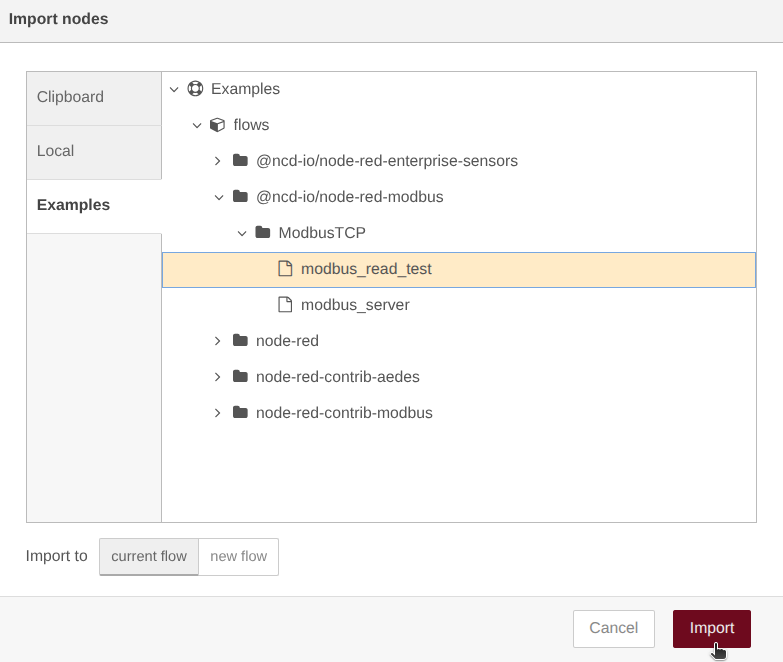
Open the folder path: @ncd-io/node-red-modbus > ModbusTCP.
Select the modbus_read_test flow and click the Import button.
If you see a pop up window indicating ‘Some of the nodes you are importing already exist in your flow workspace’, click on Import copy button.
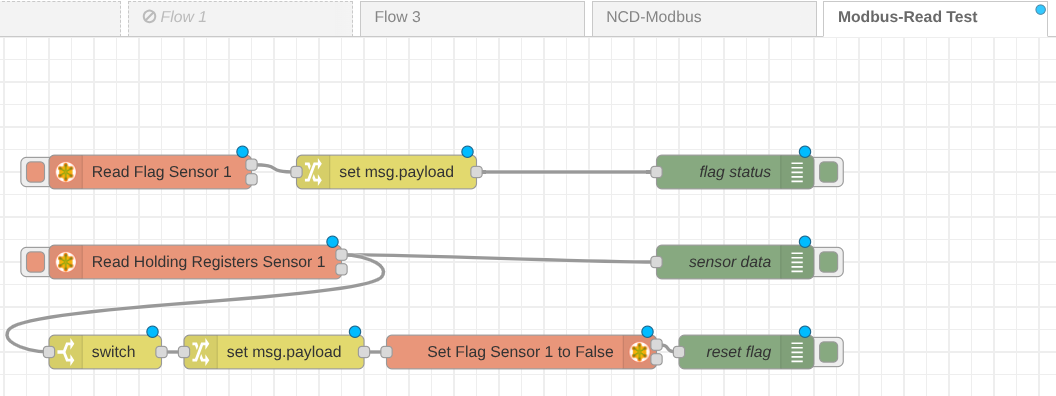
This is a fundamental flow designed to demonstrate the Modbus polling process. It includes two primary Modbus Read nodes:
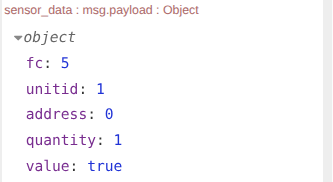
Read Flag Sensor 1: This node monitors the sensor’s status flag to determine if new data is available. The output will be a boolean value (True/False) based on the current state of that register.
Read Holding Registers: This node is triggered only if the previous “Flag” node returns True. It reads the actual sensor data stored in the Holding Registers.
Auto-Reset Logic: Additionally, this flow is configured to automatically evaluate the output; once the data is successfully read, it sends a command to reset the sensor flag to False. This prepares the system for the next data transmission cycle.
You can easily modify this flow to test your specific Modbus Server configuration and overall logic functionality.
Click to Expand
Physical and Network Layer Configuration
Locate the Ethernet port labeled ETH1 on your Enterprise IIoT Gateway. By default, this port is configured to act as a network router/host.
Use a standard Ethernet cable to connect your PLC or PC directly to the ETH1 port.
Use a standard Ethernet cable to connect your PC’s/PLC Ethernet port directly to the ETH1 port on the Enterprise IIoT Gateway.
Network Layer (IP Addresses)
For the Modbus Client (PLC/PC) to communicate with the Modbus Server (Gateway), they must reside on the same IP subnet.
Gateway IP (Server):
The gateway’s ETH1 port comes pre-configured with a static IP address: 192.168.0.1. It also runs an onboard DHCP server, meaning it will automatically assign a compatible IP address to any device plugged into it.
PC/PLC IP Configuration (Client): If you are using a PC to test the connection:
Go to Control Panel > Network and Sharing Center > Change adapter settings.
Right-click your Ethernet adapter and select Properties.
Select Internet Protocol Version 4 (TCP/IPv4) and click Properties.
Select Obtain an IP address automatically. This allows the Gateway’s DHCP server to assign your PC an address (e.g., 192.168.0.2).
Click OK to save.
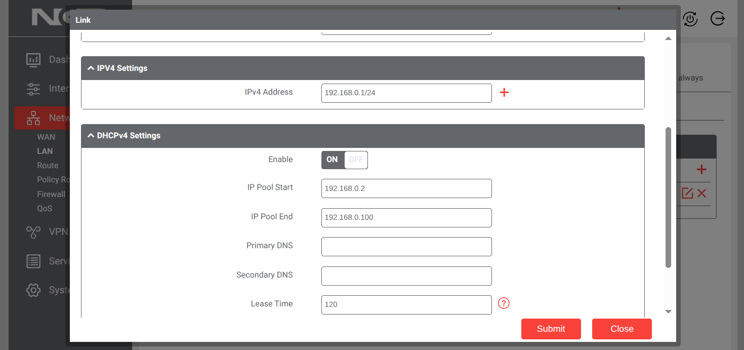
NoteYou can alter the ETH1 LAN settings via the Gateway's web dashboard. Navigate to Network -> LAN, click the pencil icon, and adjust the IPv4 host address and DHCP pool as needed for your facility's IT requirements.
Modbus data is typically transmitted as raw 16-bit integer values. You will likely need to convert these values into human-readable engineering units (e.g., temperature, pressure, vibration) on the client side (in your PLC logic or SCADA software).
Please refer to the API Overview Document located under the resources tab on your specific sensor’s product web page. The “Data Payload” section provides the exact byte mapping required to accurately decode the sensor values.