
Step 1: Run Alpha Station and click the “I2C Bus Scanner and ProXR Linker” button.
Step 2: Click “Scan I2C Ports” to build a list of connected I2C Devices on all ports (Step 3).
This list can get large if there are many devices connected.
Important: The scan will display all addresses in the order they are discovered. The address numbers shown above (0x20-0x24) are in sequence with no gaps, meaning all addresses are used in consecutive order. For best results, we strongly suggest setting the jumpers on your relay boards in perfect ascending order with no gaps in address as shown. Also note that a 24 or 32 channel relay controller will appear as two addresses because there are two control chips.
Step 4: Click “Edit”.
Step 5: Choose a Driver that Best Matches your Controller, Use the Guide Below to Better Understand Driver Types
MCP23008 1-Channel Driver + 7 GPIO – Use this driver if you are working with a 1-Channel Relay Controller
MCP23008 2-Channel Driver + 6 GPIO – Use this driver if you are working with a 2-Channel Relay Controller
MCP23008 4-Channel Driver + 4 GPIO – Use this driver if you are working with a 4-Channel Relay Controller
MCP23008 8-Channel Driver – Use this driver if you are working with a 8-Channel Relay Controller
MCP23008 8-Channel GPIO – Use this driver if you are working with a 8-Channel General Purpose Input Output Controller with No On-Board Relays.
MCP23017 16-Channel 8-Input + 8 GPIO – Use this driver if you are working with a 16-Channel General Purpose Input Output Controller with No On-Board Relays.
MCP23017 8-Channel Driver + 8 GPIO – This driver is commonly used to as the second address of a 24-Channel Relay Controller. The first 16-channels are relays, the second 16-channels are divided between relays and GPIO. In the examble screen shot above, address 0x20 is mapped to 16 relays while addres 0x21 is mapped to 8 relays + 8 GPIO. This is the proper sequence of mapping a 24-Channel relay controller.
MCP23017 12-Channel Driver + 4 GPIO – This driver is reserved for future use, we do not currently offer a controller with 12-Channel relays, but in the future, we may choose to offer access to a driver that supports 12-channel variants.
MCP23017 16-Channel Driver – Use this driver to identify a 16-Channel relay controller or use TWO of these drivers to identify a 32-Channel relay controller.
Step 6: Click Ok.

Step 7: Review the Driver List
Review the driver list to make sure all drivers are properly mapped to the physical relays. While most drivers are easy to understand, 24 and 32-Channel relay controllers will always appear as two list items. A 24-Channel relay controller will always use a 16-Channel Relay Driver on the Lower Address and a 8-Channel Relay Driver + 8 GPIO mapped to the Upper Address. A 32-Channel relay controller is a little more straight forward as it simply uses two 16-Channel relay drivers for both the Lower and Upper addresses.
Step 8: Write the Driver Map to the Controller
Once the driver map is written, the controller will be ready to control all relays using the driver specified in the list. This portion of memory is protected from accidental writes, so it will be necessary to use Alpha Station any time a change to the relay controller is needed.
- ProXR Enterprise Command Structure
endNodes use simple commands to control relays once the relay driver has been defined (in the previous section). Many ProXR Enterprise commands allow for optional parameters to enhance a command for a specific application. Please make SURE you are wrapping ALL commands in the NCD API Structure using the API Calculator.
ProXR Enterprise and Alpha Station
Alpha Station will be critical to learning the command structure of NCD ProXR Enterprise controllers. As User Interface elements are clicked, Alpha Station will generate and send commands to the relay controller for execution. Alpha Station will also display response codes, which frequently indicate relay status. Many commands include options, which allows you to extend the capabilities of some functions. Since commands can be routed to different I2C ports and different relay banks, there is a tremendous amount of flexibility (and variability) in the way commands are executed. This guide will explain many of the commands and options, but it’s not feasible to generate a list of every command with every possible option. Instead, we strongly advise using Alpha Station, click on UI elements, watch the Send and Receive boxes as they send and receive properly structured ProXR Enterprise commands to the relay controller.
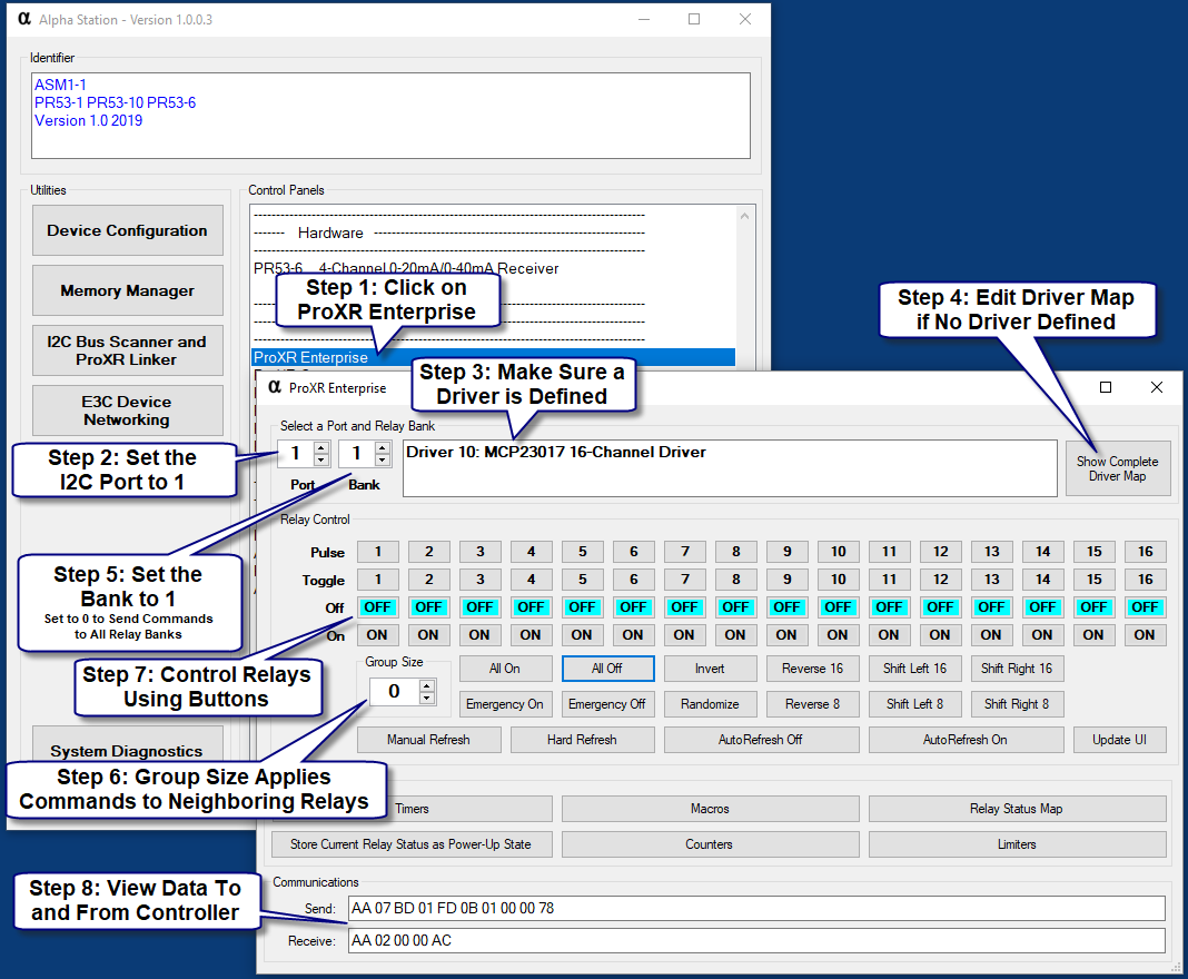
Follow the balloons as shown in numeric order.
Step 1: Click on “ProXR Enterprise” in Alpha Station to open the ProXR Enterprise Relay Control Panel.
Step 2: Select the I2C Port that has Relays Attached. In Most Cases, this will be I2C Port 1. Larger controllers will allow you to select higher port numbers. Up to 16 ports are supported for the largest possible controllers.
Step 3: Make Sure a Driver is Defined for the selected I2C Port. If the Driver says “None”, you will not be able to control relays. This indicates relays have not been mapped to the selected I2C Port. This can be corrected by clicking on D.
Step 4: “Show Complete Driver Map” is only necessary if the Driver says “None”. Use this button to map a relay driver to the selected I2C Port. This is explained earlier in this guide.
Step 5: Select the Relay Bank you want to control. Relay Bank 1 May Contain from 1 to 16 Relays, Depending on your Controller. The relay bank setting is how you will talk to additional relay controllers attached to the selected I2C Port.
Step 6: Choose a Grouping Value. Grouping is used to control neighboring relays. A grouping value of 0 is normal, meaning the On/Off buttons control only a single relay. Set the grouping value to 1 and experiment with the On/Off buttons. You will see the selected relays will be controlled, along with one neighboring relay. This will allow you to control relays in “pairs”. A grouping value of 3 will control up to 3 additional relays (for a total of 4 relays) with a single on/off button. Change the Grouping Value and Turn Relays On and Off for a full demonstration of how grouping affects neighboring relays. Grouping is very useful when you need a single function to control many relays at one time.
Step 7: Experiment with the different relay control commands.
Step 8: As you click on interface elements, you will see all data transmitted and received. Every command generates a response. Most responses are used to report the status of relays affected by relay control commands. You may copy these byte values direction into your own software to perform the exact same functions as the user interface.
Directing Commands to I2C Ports
Since ProXR Enterprise is based on the I2C framework, and up to 16 I2C ports are available on some versions, it’s important to address the I2C port direction commands as the first order of business. Port direction commands will direct all of your ProXR commands to a specific I2C port. While port direction commands are technically optional, they are strongly advised for the purposes of scalability. Should they be omitted, you will enjoy communication speed that is only a few microseconds faster, but your software will need a major structural re-write if you decide to expand to more than a single I2C port. For this reason, we need to dive into port direction commands once again to see how they affect ProXR Enterprise.
| Port direction commands are fully documented earlier in this guide, please see: |
| I2C Command Set > Selecting a I2C Port |
If a ProXR Enterprise controller is equipped with more than one I2C Port, it’s best to describe the device as having multiple relay controllers. For instance, if a ProXR enterprise device is equipped with 16 I2C Ports, there are essentially 16 separate I2C relay controllers in firmware. To better understand this architecture, it’s important to explain how ProXR Enterprise functions. ProXR Enterprise has the ability to speak to a single relay or to all relays on a single I2C port. It is not possible to send a ProXR Enterprise command to all relays on all I2C ports (with the exception of Emergency commands, which will be discussed later). So in this way, it’s best to think of each I2C port as a separate relay controller. You can tell a relay to turn on, you can tell a relay to turn off and apply this command to all relay banks on a single port, but you cannot direct the “On” command to all relay banks on all I2C ports.
The 0xBD command is used to direct ProXR Enterprise commands to a specific port. For instance, 0xBD 0x01 will direct all subsequent commands to I2C Port 1. Similarly, 0xBD 0x10 will direct all ProXR Enterprise commands to I2C Port 16.
Byte 1: 0xBD is the Command header for I2C Port Direction
Byte 2: 0x01-0x10 is the I2C Port Selection (I2C Port 1 to 16)
Example: Direct Communications to I2C Port 1
Send: 0xBD, 0x01
Please use the API Calculator to Properly Encode All Commands.
Structuring ProXR Enterprise Commands
Now let’s take a look a ProXR Enterprise commands. All ProXR Enterprise Commands will begin with 0xFD. This command header serves as a branch into the ProXR Enterprise command set. Any commands with 0xFD will be processed by the ProXR Enterprise firmware. Note that previous generations of ProXR used 0xFE as the command header. Since ProXR Enterprise is vastly different in structure and capabilities, a new header is needed. Any header outside 0xFD will be ignored by the ProXR Enterprise firmware. Similarly, any commands that do not begin 0xFD will not be covered in this section. Most ProxR commands are 4 to 7 bytes in length, following the general structure shown below:
General Structure:
Byte 1: 0xFD is the command header (253)
Byte 2: 0x00-0x14 Relay Control Function (0-20)
Byte 3: 0x01-0x10 Bank Selection (1-16)
Byte 4: 0x01-0x10 Relay Number (1-16)
Bytes 5-7: Command Options Vary in Length and Function
Example: Turn On Relay 1
Send: 0xFD, 0x01, 0x01, 0x01, 0x00
Please use the API Calculator to Properly Encode All Commands.
Though it is possible to activate a relay with this command, it’s much better to always specify the I2C Port along with the command. We essentially merge the two samples shown above together:
Properly Structured Command Includes the I2C Port with the Command:
Send: 0xBD 0x02 0xFD 0x01 0x01 0x01 0x00
Here's a breakdown of each byte in the frame:
Byte 1: 0xBD - Direct this Command to a Specified I2C Port
Byte 2: 0x02 - Direct this Command to I2C Port Number 2 (Valid Range is 0x01 to 0x10 [1 to 16])
Byte 3: 0xFD - ProXR Enterprise Command Header
Byte 4: 0x01 - ProXR Enterprise Turn On Relay Function
Byte 5: 0x01 - ProXR Enterprise Relay Bank 1 (A Value of 0 Will Direct this Command to All Relay Banks)
Byte 6: 0x01 - ProXR Enterprise Relay 1
Byte 7: 0x00 - ProXR Enterprise Command Options (0 = No Option)
Please use the API Calculator to Properly Encode All Commands.
Introductory Summary
In the above sections, we learned the following:
- How to Alpha Station
- How to Map your Relay Controllers to the I2C Ports of your endNode Device
- How to Turn On Relay 1
- How to Direct this Command to I2C Port 2
- How to Join the Two Commands Together into a Single Command
- We use the API Calculator to Wrap Commands for USB and Wireless Communications
ProXR Enterprise Library
STOP HERE
Relay Control Functions
Let’s take a dive into the different functions that are available for ProXR Enterprise. We will be discussing the “short structure” for each command below, but many of the samples will be given in a fully wrapped API structure so you can test immediately. In this section, we will discuss simply how to read the structures provided in the samples below so that you may extract the information you require.
In the samples below, you will see 0xBD followed by a value of 0x01 to 0x10. This will direct a command to specific I2C Port. Most samples will use 0xBD 0x01 to direct the command to I2C Port 1. So anytime you see 0xBD 0x01, please note this is simply forwarding the command to a particular I2C port.
In the samples below, you will also see commands that begin 0xFD, this is the ProXR Enterprise command header. The bytes following will indicate the command and any associated parameters.
Many times will see a full NCD API Structure. A NCD API Frame always begins with 0xAA, followed by the total number of bytes in the command 0x07 is shown in the sample below. The payload of the NCD API frame is the 7 bytes of data beginning with 0xBD. The last byte is the 8-Bit checksum of all preceding bytes.
So let’s break down the “Relay On” command once again:
Send: 0xBD 0x02 0xFD 0x01 0x01 0x01 0x00
Byte 1: 0xBD - Direct this Command to a Specified I2C Port
Byte 2: 0x02 - Direct this Command to I2C Port Number 2 (Valid Range is 0x01 to 0x10 [1 to 16])
Byte 3: 0xFD - ProXR Enterprise Command Header
Byte 4: 0x01 - ProXR Enterprise Turn On Relay Function
Byte 5: 0x01 - ProXR Enterprise Relay Bank 1 (A Value of 0 Will Direct this Command to All Relay Banks)
Byte 6: 0x01 - ProXR Enterprise Relay 1
Byte 7: 0x00 - ProXR Enterprise Group Size Option (0 = Selected Relay Only)
Please use the API Calculator to Properly Encode All Commands.
This command will return 1 or 2 bytes of data. If a Bank value of 0 in the previous command is specified, this function will simply confirm processing by responding with a 0x55 response code. Any Bank value other than 0 will return the following 2 bytes:
Byte 1: MSB - Reports the Upper 8 Bits of a 16-Bit Word indicating the Current Status of the Relay Bank Affected by the Last Command
Byte 2: LSB - Reports the Lower 8 Bits of a 16-Bit Word indicating the Current Status of the Relay Bank Affected by the Last Command
Function 0: Turn Relays Off
The following “Relay Off” Command structure should be used to specify the I2C Port, Bank, Relay, and Group to control. This command will turn off the specified relays.
Byte 1: 0xBD - Direct this Command to a Specified I2C Port
Byte 2: 0x02 - Direct this Command to I2C Port Number 2 (Valid Range is 0x01 to 0x10 [1 to 16])
Byte 3: 0xFD - ProXR Enterprise Command Header
Byte 4: 0x00 - ProXR Enterprise Turn Off Relay Function
Byte 5: 0x01 - ProXR Enterprise Relay Bank 1 (Valid Range is 0x00 to 0x08) (0x00 = All Relay Banks, 0x01 = Bank 1, 0x08 = Bank 8)
Byte 6: 0x01 - ProXR Enterprise Relay 1 (Valid Range is 0x01 to 0x10 [1 to 16])
Byte 7: 0x00 - ProXR Enterprise Group Size Option (Valid Range is 0x00 to 0x0F, 0 = Selected Relay Only, 0x01 = +1 Additional Relay, 0x0F = +15 Additional Relays)
Usage Examples:
Go to I2C Port 1, Turn Off Relay 1, Bank 1: 0xBD 0x01 0xFD 0x00 0x01 0x01 0x00
Go to I2C Port 1, Turn Off Relay 3, Bank 1: 0xBD 0x01 0xFD 0x00 0x01 0x03 0x00
Go to I2C Port 1, Turn Off Relay 7, Bank 1: 0xBD 0x01 0xFD 0x00 0x01 0x07 0x00
Please use the API Calculator to Properly Encode All Commands.
The Group Size option allows you to turn off additional relays. To use this option, specify the first relay that you would like to shut off and use a grouping value of 1 to 15 turn off 1 to 15 additional relays past the first relay. A grouping value of 0 will control only a single relay. A grouping value of 1 will turn off the specified relay plus one additional relay. A grouping value of 4 will turn off the specified relay plus 4 additional relays.
Go to I2C Port 1, Turn Off Relays 1 and 2 on Bank 1 using Grouping Option 0: 0xBD 0x01 0xFD 0x00 0x01 0x01 0x01
Go to I2C Port 1, Turn Off Relays 3, 4, 5 on Bank 1 using Grouping Option 2: 0xBD 0x01 0xFD 0x00 0x01 0x03 0x02
Go to I2C Port 1, Turn Off Relays 7-15 on Bank 1 using Grouping Option 8:    0xBD 0x01 0xFD 0x00 0x01 0x07 0x08
Please use the API Calculator to Properly Encode All Commands.
This command will return 1 or 2 bytes of data. If a Bank value of 0 in the previous command is specified, this function will simply confirm processing by responding with a 0x55 response code. Any Bank value other than 0 will return the following 2 bytes:
Byte 1: MSB - Reports the Upper 8 Bits of a 16-Bit Word indicating the Current Status of the Relay Bank Affected by the Last Command
Byte 2: LSB - Reports the Lower 8 Bits of a 16-Bit Word indicating the Current Status of the Relay Bank Affected by the Last Command
Library Integration: NCDLib.Enterprise.ProXR.TurnOffRelay(NCDComponent1, Port.Value, Bank.Value, Relay.Value, GroupSize.Value)
Function 1: Turn Relays On
The following “Relay On” Command structure should be used to specify the I2C Port, Bank, Relay, and Group to control. This command will turn on the specified relays.
Byte 1: 0xBD - Direct this Command to a Specified I2C Port
Byte 2: 0x02 - Direct this Command to I2C Port Number 2 (Valid Range is 0x01 to 0x10 [1 to 16])
Byte 3: 0xFD - ProXR Enterprise Command Header
Byte 4: 0x01 - ProXR Enterprise Turn On Relay Function
Byte 5: 0x01 - ProXR Enterprise Relay Bank 1 (Valid Range is 0x00 to 0x08) (0x00 = All Relay Banks, 0x01 = Bank 1, 0x08 = Bank 8)
Byte 6: 0x01 - ProXR Enterprise Relay 1 (Valid Range is 0x01 to 0x10 [1 to 16])
Byte 7: 0x00 - ProXR Enterprise Group Size Option (Valid Range is 0x00 to 0x0F, 0 = Selected Relay Only, 0x01 = +1 Additional Relay, 0x0F = +15 Additional Relays)
Please use the API Calculator to Properly Encode All Commands.
This command will return 1 or 2 bytes of data. If a Bank value of 0 in the previous command is specified, this function will simply confirm processing by responding with a 0x55 response code. Any Bank value other than 0 will return the following 2 bytes:
Byte 1: MSB - Reports the Upper 8 Bits of a 16-Bit Word indicating the Current Status of the Relay Bank Affected by the Last Command
Byte 2: LSB - Reports the Lower 8 Bits of a 16-Bit Word indicating the Current Status of the Relay Bank Affected by the Last Command
Library Integration: NCDLib.Enterprise.ProXR.TurnOnRelay(NCDComponent1, Port.Value, Bank.Value, Relay.Value, GroupSize.Value)
Function 2: Toggle Relay State
The following “Relay Toggle” Command structure should be used to specify the I2C Port, Bank, and Relay to control. The Toggle command is used to change the current state of a relay to the opposite state. For instance, every time the toggle command is sent, the relay cycle between turn on and off.
Byte 1: 0xBD - Direct this Command to a Specified I2C Port
Byte 2: 0x02 - Direct this Command to I2C Port Number 2 (Valid Range is 0x01 to 0x10 [1 to 16])
Byte 3: 0xFD - ProXR Enterprise Command Header
Byte 4: 0x02 - ProXR Enterprise Toggle Relay Function
Byte 5: 0x01 - ProXR Enterprise Relay Bank 1 (Valid Range is 0x00 to 0x08) (0x00 = All Relay Banks, 0x01 = Bank 1, 0x08 = Bank 8)
Byte 6: 0x01 - ProXR Enterprise Relay 1 (Valid Range is 0x01 to 0x10 [1 to 16])
Byte 7: 0x00 - ProXR Enterprise Group Size Option (Valid Range is 0x00 to 0x0F, 0 = Selected Relay Only, 0x01 = +1 Additional Relay, 0x0F = +15 Additional Relays)
Please use the API Calculator to Properly Encode All Commands.
This command will return 1 or 2 bytes of data. If a Bank value of 0 in the previous command is specified, this function will simply confirm processing by responding with a 0x55 response code. Any Bank value other than 0 will return the following 2 bytes:
Byte 1: MSB - Reports the Upper 8 Bits of a 16-Bit Word indicating the Current Status of the Relay Bank Affected by the Last Command
Byte 2: LSB - Reports the Lower 8 Bits of a 16-Bit Word indicating the Current Status of the Relay Bank Affected by the Last Command
Library Integration: NCDLib.Enterprise.ProXR.ToggleRelay(NCDComponent1, Port.Value, Bank.Value, Relay.Value, GroupSize.Value)Function 3: Pulse Relay State
The following “Relay Pulse” Command structure should be used to specify the I2C Port, Bank, and Relay to control. The Pulse command is used to temporarily turn relays On or Off. If relays are currently off, the pulse command will briefly turn on the specified relays. If the relays are currently on, the pulse command will briefly turn on the specified relays. If relays are mixed on or off, all specified relays will pulse to the opposite state.
Byte 1: 0xBD - Direct this Command to a Specified I2C Port
Byte 2: 0x02 - Direct this Command to I2C Port Number 2 (Valid Range is 0x01 to 0x10 [1 to 16])
Byte 3: 0xFD - ProXR Enterprise Command Header
Byte 4: 0x03 - ProXR Enterprise Pulse Relay Function
Byte 5: 0x01 - ProXR Enterprise Relay Bank 1 (Valid Range is 0x00 to 0x08) (0x00 = All Relay Banks, 0x01 = Bank 1, 0x08 = Bank 8)
Byte 6: 0x01 - ProXR Enterprise Relay 1 (Valid Range is 0x01 to 0x10 [1 to 16])
Byte 7: 0x00 - ProXR Enterprise Group Size Option (Valid Range is 0x00 to 0x0F, 0 = Selected Relay Only, 0x01 = +1 Additional Relay, 0x0F = +15 Additional Relays)
Please use the API Calculator to Properly Encode All Commands.
This command will return 1 or 2 bytes of data. If a Bank value of 0 in the previous command is specified, this function will simply confirm processing by responding with a 0x55 response code. Any Bank value other than 0 will return the following 2 bytes:
Byte 1: MSB - Reports the Upper 8 Bits of a 16-Bit Word indicating the Current Status of the Relay Bank Affected by the Last Command
Byte 2: LSB - Reports the Lower 8 Bits of a 16-Bit Word indicating the Current Status of the Relay Bank Affected by the Last Command
Library Integration: NCDLib.Enterprise.ProXR.PulseRelay(NCDComponent1, Port.Value, Bank.Value, Relay.Value, GroupSize.Value)Function 4: Invert Relay Status
The Invert Relays command is used to invert the state of all relays in the specified relay bank. When the Invert command is received, all relays that are off will turn on and all relays that are on will turn off. This command will affect a individual bank of up to 16 relays or all relays on the specified I2C Port.
Byte 1: 0xBD - Direct this Command to a Specified I2C Port
Byte 2: 0x02 - Direct this Command to I2C Port Number 2 (Valid Range is 0x01 to 0x10 [1 to 16])
Byte 3: 0xFD - ProXR Enterprise Command Header
Byte 4: 0x04 - ProXR Enterprise Invert Relay Bank Function
Byte 5: 0x01 - ProXR Enterprise Relay Bank 1 (Valid Range is 0x00 to 0x08) (0x00 = All Relay Banks, 0x01 = Bank 1, 0x08 = Bank 8)
Please use the API Calculator to Properly Encode All Commands.
This command will return 1 or 2 bytes of data. If a Bank value of 0 in the previous command is specified, this function will simply confirm processing by responding with a 0x55 response code. Any Bank value other than 0 will return the following 2 bytes:
Byte 1: MSB - Reports the Upper 8 Bits of a 16-Bit Word indicating the Current Status of the Relay Bank Affected by the Last Command
Byte 2: LSB - Reports the Lower 8 Bits of a 16-Bit Word indicating the Current Status of the Relay Bank Affected by the Last Command
Library Integration: NCDLib.Enterprise.ProXR.Invert(NCDComponent1, Port.Value, Bank.Value)Function 5: Reverse Relay Status 16-Bit
The Reverse Relays command is used to reverse the state of all relays in the specified relay bank. When the Reverse command is received, the status of opposing relays are swapped. Relays 1 through 8 are effectively swapped with the Relay Status of Relays 16 Through 9 respectively. Relay 1 Status is Swapped with Relay 16, Relay 2 Status is Swapped with Relay 15, Relay 8 Status is Swapped with Relay 9. This is a 16-Bit reversal for use with 16 Relays per I2C Address (MCP23017 16-Channel Driver). This command will affect a individual bank of up to 16 relays or all relays on the specified I2C Port. This function is generally used for lighting effects.
Byte 1: 0xBD - Direct this Command to a Specified I2C Port
Byte 2: 0x02 - Direct this Command to I2C Port Number 2 (Valid Range is 0x01 to 0x10 [1 to 16])
Byte 3: 0xFD - ProXR Enterprise Command Header
Byte 4: 0x05 - ProXR Enterprise 16-Bit Reverse Relay Bank Function
Byte 5: 0x01 - ProXR Enterprise Relay Bank 1 (Valid Range is 0x00 to 0x08) (0x00 = All Relay Banks, 0x01 = Bank 1, 0x08 = Bank 8)
Please use the API Calculator to Properly Encode All Commands.
This command will return 1 or 2 bytes of data. If a Bank value of 0 in the previous command is specified, this function will simply confirm processing by responding with a 0x55 response code. Any Bank value other than 0 will return the following 2 bytes:
Byte 1: MSB - Reports the Upper 8 Bits of a 16-Bit Word indicating the Current Status of the Relay Bank Affected by the Last Command
Byte 2: LSB - Reports the Lower 8 Bits of a 16-Bit Word indicating the Current Status of the Relay Bank Affected by the Last Command
Library Integration: NCDLib.Enterprise.ProXR.Reverse(NCDComponent1, Port.Value, Bank.Value)Function 6: Shift Relay Status Left 16-Bit
The Shift Relays command is used to Shift the state of all relays in the specified relay bank to the left. When the Shift Relays Left command is received, the status of all relays in the specified bank is shifted 1 place to the left. Relay 1 Status will Move to Relay 16, Relay 16 Status will Move to Relay 15, Relay 15 Status will Move to Relay 14, etc. This is a 16-Bit rotation command for use with 16 Relays per I2C Address (MCP23017 16-Channel Driver). This command will affect a individual bank of up to 16 relays or all relays on the specified I2C Port. This function is generally used for lighting effects.
Byte 1: 0xBD - Direct this Command to a Specified I2C Port
Byte 2: 0x02 - Direct this Command to I2C Port Number 2 (Valid Range is 0x01 to 0x10 [1 to 16])
Byte 3: 0xFD - ProXR Enterprise Command Header
Byte 4: 0x06 - ProXR Enterprise 16-Bit Shift Left Relay Bank Function
Byte 5: 0x01 - ProXR Enterprise Relay Bank 1 (Valid Range is 0x00 to 0x08) (0x00 = All Relay Banks, 0x01 = Bank 1, 0x08 = Bank 8)
Please use the API Calculator to Properly Encode All Commands.
This command will return 1 or 2 bytes of data. If a Bank value of 0 in the previous command is specified, this function will simply confirm processing by responding with a 0x55 response code. Any Bank value other than 0 will return the following 2 bytes:
Byte 1: MSB - Reports the Upper 8 Bits of a 16-Bit Word indicating the Current Status of the Relay Bank Affected by the Last Command
Byte 2: LSB - Reports the Lower 8 Bits of a 16-Bit Word indicating the Current Status of the Relay Bank Affected by the Last Command
Library Integration: NCDLib.Enterprise.ProXR.ShiftLeft(NCDComponent1, Port.Value, Bank.Value)Function 7: Shift Relay Status Right 16-Bit
The Shift Relays command is used to Shift the state of all relays in the specified relay bank to the right. When the Shift Relays Right command is received, the status of all relays in the specified bank is shifted 1 place to the right. Relay 1 Status will Move to Relay 2, Relay 2 Status will Move to Relay 3, Relay 16 Status will Move to Relay 1, etc. This is a 16-Bit rotation command for use with 16 Relays per I2C Address (MCP23017 16-Channel Driver). This command will affect a individual bank of up to 16 relays or all relays on the specified I2C Port. This function is generally used for lighting effects.
Byte 1: 0xBD - Direct this Command to a Specified I2C Port
Byte 2: 0x02 - Direct this Command to I2C Port Number 2 (Valid Range is 0x01 to 0x10 [1 to 16])
Byte 3: 0xFD - ProXR Enterprise Command Header
Byte 4: 0x07 - ProXR Enterprise 16-Bit Shift Right Relay Bank Function
Byte 5: 0x01 - ProXR Enterprise Relay Bank 1 (Valid Range is 0x00 to 0x08) (0x00 = All Relay Banks, 0x01 = Bank 1, 0x08 = Bank 8)
Please use the API Calculator to Properly Encode All Commands.
This command will return 1 or 2 bytes of data. If a Bank value of 0 in the previous command is specified, this function will simply confirm processing by responding with a 0x55 response code. Any Bank value other than 0 will return the following 2 bytes:
Byte 1: MSB - Reports the Upper 8 Bits of a 16-Bit Word indicating the Current Status of the Relay Bank Affected by the Last Command
Byte 2: LSB - Reports the Lower 8 Bits of a 16-Bit Word indicating the Current Status of the Relay Bank Affected by the Last Command
Library Integration: NCDLib.Enterprise.ProXR.ShiftRight(NCDComponent1, Port.Value, Bank.Value)Function 8: Reverse Relays 8-Bit
The Reverse Relays command is used to reverse the state of all relays in the specified relay bank. When the Reverse command is received, the status of opposing relays are swapped. Relays 1 through 4 are effectively swapped with the Relay Status of Relays 8 Through 5 respectively. Relay 1 Status is Swapped with Relay 8, Relay 2 Status is Swapped with Relay 7, Relay 4 Status is Swapped with Relay 5. This is a 8-Bit reversal for use with 8 Relays per I2C Address (MCP23008 8-Channel Driver). This command will affect a individual bank of up to 8 relays or all lower-8 relays on the specified I2C Port. This function is generally used for lighting effects.
Byte 1: 0xBD - Direct this Command to a Specified I2C Port
Byte 2: 0x02 - Direct this Command to I2C Port Number 2 (Valid Range is 0x01 to 0x10 [1 to 16])
Byte 3: 0xFD - ProXR Enterprise Command Header
Byte 4: 0x08 - ProXR Enterprise 8-Bit Reverse Relay Bank Function
Byte 5: 0x01 - ProXR Enterprise Relay Bank 1 (Valid Range is 0x00 to 0x08) (0x00 = All Relay Banks, 0x01 = Bank 1, 0x08 = Bank 8)
Please use the API Calculator to Properly Encode All Commands.
This command will return 1 or 2 bytes of data. If a Bank value of 0 in the previous command is specified, this function will simply confirm processing by responding with a 0x55 response code. Any Bank value other than 0 will return the following 2 bytes:
Byte 1: MSB - Reports the Upper 8 Bits of a 16-Bit Word indicating the Current Status of the Relay Bank Affected by the Last Command
Byte 2: LSB - Reports the Lower 8 Bits of a 16-Bit Word indicating the Current Status of the Relay Bank Affected by the Last Command
Library Integration: NCDLib.Enterprise.ProXR.Reverse_8(NCDComponent1, Port.Value, Bank.Value)Function 9: Shift Relay Status Left 8-Bit
The Shift Relays command is used to Shift the state of all relays in the specified relay bank to the left. When the Shift Relays Left command is received, the status of all relays in the specified bank is shifted 1 place to the left. Relay 1 Status will Move to Relay 8, Relay 8 Status will Move to Relay 7, Relay 7 Status will Move to Relay 6, etc. This is a 8-Bit rotation command for use with 8 Relays per I2C Address (MCP23008 8-Channel Driver). This command will affect a individual bank of up to 8 relays or all lower-8 relays on the specified I2C Port. This function is generally used for lighting effects.
Byte 1: 0xBD - Direct this Command to a Specified I2C Port
Byte 2: 0x02 - Direct this Command to I2C Port Number 2 (Valid Range is 0x01 to 0x10 [1 to 16])
Byte 3: 0xFD - ProXR Enterprise Command Header
Byte 4: 0x09 - ProXR Enterprise 8-Bit Shift Left Relay Bank Function
Byte 5: 0x01 - ProXR Enterprise Relay Bank 1 (Valid Range is 0x00 to 0x08) (0x00 = All Relay Banks, 0x01 = Bank 1, 0x08 = Bank 8)
Please use the API Calculator to Properly Encode All Commands.
This command will return 1 or 2 bytes of data. If a Bank value of 0 in the previous command is specified, this function will simply confirm processing by responding with a 0x55 response code. Any Bank value other than 0 will return the following 2 bytes:
Byte 1: MSB - Reports the Upper 8 Bits of a 16-Bit Word indicating the Current Status of the Relay Bank Affected by the Last Command
Byte 2: LSB - Reports the Lower 8 Bits of a 16-Bit Word indicating the Current Status of the Relay Bank Affected by the Last Command
Library Integration: NCDLib.Enterprise.ProXR.ShiftLeft_8(NCDComponent1, Port.Value, Bank.Value)Function 10: Shift Relay Status Right 8-Bit
The Shift Relays command is used to Shift the state of all relays in the specified relay bank to the right. When the Shift Relays Right command is received, the status of all relays in the specified bank is shifted 1 place to the right. Relay 1 Status will Move to Relay 2, Relay 2 Status will Move to Relay 3, Relay 8 Status will Move to Relay 1, etc. This is a 8-Bit rotation command for use with 8 Relays per I2C Address (MCP23008 8-Channel Driver). This command will affect a individual bank of up to 8 relays or all lower-8 relays on the specified I2C Port. This function is generally used for lighting effects.
Byte 1: 0xBD - Direct this Command to a Specified I2C Port
Byte 2: 0x02 - Direct this Command to I2C Port Number 2 (Valid Range is 0x01 to 0x10 [1 to 16])
Byte 3: 0xFD - ProXR Enterprise Command Header
Byte 4: 0x0A - ProXR Enterprise 8-Bit Shift Right Relay Bank Function
Byte 5: 0x01 - ProXR Enterprise Relay Bank 1 (Valid Range is 0x00 to 0x08) (0x00 = All Relay Banks, 0x01 = Bank 1, 0x08 = Bank 8)
Please use the API Calculator to Properly Encode All Commands.
This command will return 1 or 2 bytes of data. If a Bank value of 0 in the previous command is specified, this function will simply confirm processing by responding with a 0x55 response code. Any Bank value other than 0 will return the following 2 bytes:
Byte 1: MSB - Reports the Upper 8 Bits of a 16-Bit Word indicating the Current Status of the Relay Bank Affected by the Last Command
Byte 2: LSB - Reports the Lower 8 Bits of a 16-Bit Word indicating the Current Status of the Relay Bank Affected by the Last Command
Library Integration: NCDLib.Enterprise.ProXR.ShiftRight_8(NCDComponent1, Port.Value, Bank.Value)Function 11: Write Data to Relay Banks
The Write Byte/Word function allows you to send a byte or a word directly to a relay bank. This function allows tremendous flexibility because it allows you to control relays in a binary pattern. Sending the byte value of 0x00 will turn all relays off, sending 0xFF will turn all relays on, sending 0x55 will turn on every other relay as the equivalent binary pattern of 0x55 is %01010101. To send a send a word, the optional Byte 7 may be included as shown below. This command will effectively work with 6 or 7 bytes of data depending, depending on your application requirements.
Byte 1: 0xBD - Direct this Command to a Specified I2C Port
Byte 2: 0x02 - Direct this Command to I2C Port Number 2 (Valid Range is 0x01 to 0x10 [1 to 16])
Byte 3: 0xFD - ProXR Enterprise Command Header
Byte 4: 0x0B - ProXR Enterprise Write to Relay Bank Function
Byte 5: 0x01 - ProXR Enterprise Relay Bank 1 (Valid Range is 0x00 to 0x08) (0x00 = All Relay Banks, 0x01 = Bank 1, 0x08 = Bank 8)
Byte 6: 0xFF - LSB - Least Significant Byte (Required, Valid Range 0x00-0xFF)
Byte 7: 0xFF - MSB - Most Significant Byte (Optional, Valid Range 0x00-0xFF) This Byte is Optional and May be Omitted for 8-Bit Appllications
Please use the API Calculator to Properly Encode All Commands.
This command will return 1 or 2 bytes of data. If a Bank value of 0 in the previous command is specified, this function will simply confirm processing by responding with a 0x55 response code. Any Bank value other than 0 will return the following 2 bytes:
Byte 1: MSB - Reports the Upper 8 Bits of a 16-Bit Word indicating the Current Status of the Relay Bank Affected by the Last Command
Byte 2: LSB - Reports the Lower 8 Bits of a 16-Bit Word indicating the Current Status of the Relay Bank Affected by the Last Command
Library Integration: NoneFunction 12: Randomize Relays 16-Bit
The Randomize Relays command will apply a pseudo-random function to randomly set the on/off status of relays in the specified relay banks. A Bank value of 0 will randomize all relays on the selected I2C port. A Bank value of 1 to 8 will apply the random function to the specified bank of 16 relays. Please note the Random function is not a true randomization, there is a degree of predictability and consistency associated with this function. This function is generally used for lighting effects.
Byte 1: 0xBD - Direct this Command to a Specified I2C Port
Byte 2: 0x02 - Direct this Command to I2C Port Number 2 (Valid Range is 0x01 to 0x10 [1 to 16])
Byte 3: 0xFD - ProXR Enterprise Command Header
Byte 4: 0x0C - ProXR Enterprise 16-Bit Randomize Relay Bank Function
Byte 5: 0x01 - ProXR Enterprise Relay Bank 1 (Valid Range is 0x00 to 0x08) (0x00 = All Relay Banks, 0x01 = Bank 1, 0x08 = Bank 8)
Please use the API Calculator to Properly Encode All Commands.
This command will return 1 or 2 bytes of data. If a Bank value of 0 in the previous command is specified, this function will simply confirm processing by responding with a 0x55 response code. Any Bank value other than 0 will return the following 2 bytes:
Byte 1: MSB - Reports the Upper 8 Bits of a 16-Bit Word indicating the Current Status of the Relay Bank Affected by the Last Command
Byte 2: LSB - Reports the Lower 8 Bits of a 16-Bit Word indicating the Current Status of the Relay Bank Affected by the Last Command
Library Integration: NCDLib.Enterprise.ProXR.Randomize(NCDComponent1, Port.Value, Bank.Value)Function 13: Timer Control Functions
ProXR Enterprise Timers make it possible to execute relay control operations for a user preset period of time. For instance, turn a light on for 20 minutes, or flash a relay for 3 minutes. Timers are useful to perform a particular operation for a designated period of time. Up to 32 timers may be reconfigured and triggered using simple commands. Timers are reconfigured in FRAM using Alpha Station. In the event power is lost, FRAM timers will resume operation when power is restored. Once timers are configured, timers may be controlled using the timer control functions. Exact time matching (turn on a light at 5:30pm) is not supported by ProXR Enterprise, as this should be done at the software or server level.
To get started using timers, please use Alpha Station and open the timer control panel as shown below.

A) Select the Timer you would like to Edit. There are 32 Timers available, each timer runs in the background independently.
B) Set the Hours, Minutes, and Seconds. When a timer is activated, the Hours, Minutes, and Seconds are loaded into the timer and the timer begins counting down in 1/4 second increments.
C) Set timer Options in this box. All are self explanatory except the Pause Timer function. In some cases, a recursive timer cannot be stopped without storing the “Pause Timer” option. Most of the time, you should leave this option unchecked.
D) When a Timer expires (counts down to 0 Hours, 0 Minutes, and 0 Seconds), the Timer will trigger about any command you could ever want. The Command Builder (described below) will help you build a common command, but timers are not limited to the Command Builder. Any control function can be triggered from a timer.
E) Save your Timer with this button.
F) Save and Execute your Timer with this button. The selected timer will begin counting down.
G) Use this part of the control panel to select a timer and apply one of the four button commands shown. Clearing a timer is the same turning it off.
Command Builder
The Command Builder is frequently referenced in Alpha Station. Use the Command Builder to generate a common command instead of looking it up in the manual. Please note that not all commands are supported in the Command Builder, but most common commands are available for use.

The Command Builder has many buttons with controls that change contents. Generally speaking, you should work from left to right in columns A through E as shown above.
A) Start by making a selection in this column.
B) Choose the I2C Port you would like to apply the command to.
C) Choose a Relay Control Function.
D) Choose the Relay Bank to Apply this Function.
E) Choose a Relay to Control.
F) Click the Generate Command button to build the relevant command.
G) The newly generated command will be shown here.
H) Erase your command with this button.
I) Click OK to keep your command or Cancel to exit this control panel.

A) The Command Shown in the Command Builder will be shown here.
B) To see your settings, click the “Show More” button.
At this point, you may want to click the “Save Timer + Execute”. This will start your timer.
C) Click the Refresh Button and watch the values change. You will see the timer count down each time the “Refresh” button is pressed. When the timer expires, the (A) command will be executed.
Controlling Timers with Commands
The following commands may be used to trigger or control timers from your own software. Please note that I2C Port Direction commands have no use in this function.
Byte 1: 0xFD - ProXR Enterprise Command Header
Byte 2: 0x0D - ProXR Enterprise Timer Control Function
Byte 3: 0x02 - ProXR Enterprise Timer Function (Described Below)
Timer Function Values: Valid Range = 0x00 to 0x07
Byte 3 Function: 0x00 - Pause All Timers - All Timers will Stop Counting Down
Byte 3 Function: 0x01 - Resume All Timers - All Timers will Continue to Counting Down
Byte 3 Function: 0x02 - Load and Run All timers - All Timers will be Loaded from FRAM and Begin Counting Down
Byte 3 Function: 0x03 - Clear All Timers - All Timers will Expire
Byte 3 Function: 0x04 - Pause Selected Timer - Requires Byte 4 Below
Byte 3 Function: 0x05 - Resume Selected Timer - Requires Byte 4 Below
Byte 3 Function: 0x06 - Load and Run Selected Timer - Requires Byte 4 Below
Byte 3 Function: 0x07 - Clear Selected Timer - Requires Byte 4 Below
Byte 4: 0x01-0x20 - Timer Parameter Specifies a Specific Timer - Only Used if Function Byte 3 = 0x04-0x07
Please use the API Calculator to Properly Encode All Commands.
Timer commands will return a 0x55 response code once completed.
Library Integration:
NCDLib.Enterprise.ProXR.Timers.PauseAllTimers(NCDComponent1)
NCDLib.Enterprise.ProXR.Timers.PauseSelectedTimer(NCDComponent1, TimerNumber.Value)
NCDLib.Enterprise.ProXR.Timers.ResumeAllTimers(NCDComponent1)
NCDLib.Enterprise.ProXR.Timers.ResumeSelectedTimer(NCDComponent1, TimerNumber.Value)
NCDLib.Enterprise.ProXR.Timers.LoadRunAllTimers(NCDComponent1)
NCDLib.Enterprise.ProXR.Timers.LoadRunSelectedTimer(NCDComponent1, TimerNumber.Value)
NCDLib.Enterprise.ProXR.Timers.ClearAllTimers(NCDComponent1)
NCDLib.Enterprise.ProXR.Timers.ClearSelectedTimer(NCDComponent1, TimerNumber.Value)
Function 14: Macro Control Functions
Macros are very useful if you need a endNode device to do many things with a single command. Macros make it possible for a single command to trigger a list of up to eight commands. Up to 32 Macros are available for user configuration. With additional command options, triggering multiple macros simultaneously is also possible. Macros also have the ability to trigger themselves or other Macros in an endless loop. Of course we do support commands for shutting down endless loop situations. Please note that due to a heavy workload, the possibility does exist that in certain situations, a Macro may occasionally skip one or more commands in the list. While this is a rare condition, the unavoidable potential does exist, so please be aware.

A) From Alpha Station, click on “ProXR Macros”.
B) Choose the Macro you would like to edit. Up to 32 Macros are available.
C) Macros are executed in the order listed, starting with line 1. Each line contains Byte level commands. Issuing Macro commands is the same as sending bytes the endNode controller. The only difference is, the results will be suppressed instead of sending out the communications port.
D) Use the Edit Command function to edit the bytes for each Macro. The Command Builder will be used for entry (covered above in the Timers section of this guide). Using the Command Builder will allow you to choose from many common commands via the user interface or enter specific commands at the byte level.
E) Once all the commands have been edited, be sure to Save the Macro. It will not be possible to trigger a Macro until it is saved. You will loose your commands if change to another Macro (Using B Above).
F) You can test your Macro using the buttons provided. Be sure your Macro is saved or these buttons will have no effect.
G) The first 16 Macros may be triggered as a group by checking the Macros you would like to trigger and then clicking on “Trigger Selected Macros”. Macros will be executed in the numerical order of the check boxes.
Trigger or Cancel Macros
Trigger a Individual Macro. This command will flag a Macro for background execution. Once complete, the Macro flag bit for the associated macro will be automatically cleared.
Byte 1: 0xFD - ProXR Enterprise Command Header
Byte 2: 0x0E - ProXR Enterprise Macro Control Functions
Byte 3: 0x01 - ProXR Enterprise Macro to Trigger (Valid Range is 0 to 32) A Value of 0 will Cancel All Macros, while a Value of 1-32 will Trigger Macros
Please use the API Calculator to Properly Encode All Commands.
This command will return 4 bytes indicating the Macro Flags that have been set for processing. Each bit of each byte represents an individual Macro.
Byte 1: LO_MSB - Macros 9-16 are Represented by this Byte
Byte 2: LO_LSB - Macros 1-8 are Represented by this Byte
Byte 3: HI_MSB - Macros 17-24 are Represented by this Byte
Byte 4: HI_LSB - Macros 25-32 are Represented by this Byte
Library Integration:
NCDLib.Enterprise.ProXR.Macros.Trigger_Macro(NCDComponent1, Macro.Value)
NCDLib.Enterprise.ProXR.Macros.Cancel_All_Macros(NCDComponent1)
Trigger Macro Word
The first 16 macros may be triggered simultaneously in any combination, but will be processed in their numeric order. By sending a word value to the Macro Flag controller, up to 16 Macros will be triggered in the binary bit-order of the word value. This is the same as checking the boxes in the Alpha Station UI (Section G) and clicking the “Trigger Selected Macros” button.
Byte 1: 0xFD - ProXR Enterprise Command Header
Byte 2: 0x0E - ProXR Enterprise Macro Control Functions
Byte 3: 0x21 - ProXR Enterprise Macro Word Trigger - Macros 1-16 will be Triggered in the Binary Pattern of the Word Value
Byte 4: 0x00 - ProXR Enterprise Macro Word - MSB of Macro Flag Buffer
Byte 5: 0x05 - ProXR Enterprise Macro Word - LSB of Macro Flag Buffer (Example Triggers Macros 1 and 3)
Please use the API Calculator to Properly Encode All Commands.
This command will return 4 bytes indicating the Macro Flags that have been set for processing. Each bit of each byte represents an individual Macro.
Byte 1: LO_MSB - Macros 9-16 are Represented by this Byte
Byte 2: LO_LSB - Macros 1-8 are Represented by this Byte
Byte 3: HI_MSB - Macros 17-24 are Represented by this Byte
Byte 4: HI_LSB - Macros 25-32 are Represented by this Byte
Library Integration: NCDLib.Enterprise.ProXR.Macros.Trigger_Macro_Word(NCDComponent1, MSB, LSB)
Trigger All Macros
This command will trigger all 32 Macros. Macros will be executed in their numeric order.
Byte 1: 0xFD - ProXR Enterprise Command Header
Byte 2: 0x0E - ProXR Enterprise Macro Control Functions
Byte 3: 0x22 - ProXR Enterprise Trigger all Macros - Macros 1-32 will be Triggered in Macro Numeric Order
Please use the API Calculator to Properly Encode All Commands.
This command will return 4 bytes indicating the Macro Flags that have been set for processing. Each bit of each byte represents an individual Macro.
Byte 1: LO_MSB - Macros 9-16 are Represented by this Byte
Byte 2: LO_LSB - Macros 1-8 are Represented by this Byte
Byte 3: HI_MSB - Macros 17-24 are Represented by this Byte
Byte 4: HI_LSB - Macros 25-32 are Represented by this Byte
Library Integration: NCDLib.Enterprise.ProXR.Macros.Trigger_All_Macros(NCDComponent1)Function 15: Get 8-Bit Relay Status
This function will return the On/Off status of a Relay bank. Since relay banks are 16-Bits per Bank, the 8-Bit version of this command will return only the LSB of a Bank Status Word. Convert the result to Binary to easily see the status of a relay bank.
Byte 1: 0xBD - Direct this Command to a Specified I2C Port
Byte 2: 0x02 - Direct this Command to I2C Port Number 2 (Valid Range is 0x01 to 0x10 [1 to 16])
Byte 3: 0xFD - ProXR Enterprise Command Header
Byte 4: 0x0F - ProXR Enterprise Get 8-Bit Relay Bank Status
Byte 5: 0x01 - ProXR Enterprise Relay Bank 1 (Valid Range is 0x01 to 0x08)
Please use the API Calculator to Properly Encode All Commands.
This command will return 1 byte of data indicating the status of the relays:
Byte 1: LSB - Reports the Lower 8 Bits of a 16-Bit Word indicating the Current Status of the Relay Bank
Library Integration: None
Function 16: Get 16-Bit Relay Status
This function will return the On/Off status of a Relay bank. Since relay banks are 16-Bits per Bank, this command will return a word (2 bytes). Convert the result to Binary to easily see the status of a relay bank.
Byte 1: 0xBD - Direct this Command to a Specified I2C Port
Byte 2: 0x02 - Direct this Command to I2C Port Number 2 (Valid Range is 0x01 to 0x10 [1 to 16])
Byte 3: 0xFD - ProXR Enterprise Command Header
Byte 4: 0x10 - ProXR Enterprise Get 16-Bit Relay Bank Status
Byte 5: 0x01 - ProXR Enterprise Relay Bank 1 (Valid Range is 0x01 to 0x08)
Please use the API Calculator to Properly Encode All Commands.
This command will return 2 bytes of data indicating the status of the relays.
Byte 1: MSB - Reports the Upper 8 Bits of a 16-Bit Word indicating the Current Status of the Relay Bank
Byte 2: LSB - Reports the Lower 8 Bits of a 16-Bit Word indicating the Current Status of the Relay Bank
Library Integration: NCDLib.Enterprise.ProXR.ReadStatus(NCDComponent1, Port.Value, Bank.Value)Function 17: Emergency Function
The emergency function is very unique among all ProXR Enterprise commands as this function will set the status of all relays on all I2C Ports. As the name implies, this command should be used to turn all relays on or off at the exact same time. The emergency function is also unique in that it ignores the rules of Relay Refreshing (discussed in the next section) and forces relays to update as quickly as possible.
This function accepts a 8-Bit Status parameter, which is typically set to 0x00 to turn off all relays or 0xFF to turn on all relays. Regardless of the Status value, all relays will be set to the exact same 8-bit pattern. Controllers equipped with 16 relays using a MCP23017 Driver will duplicate the pattern on the MSB as well as the LSB.
Byte 1: 0xFD - ProXR Enterprise Command Header
Byte 2: 0x11 - ProXR Enterprise Emergency Relay Status
Byte 3: 0x01 - ProXR Enterprise Status (0x00 - 0xFF where 0x00 = All Off and 0xFF = All On).
Please use the API Calculator to Properly Encode All Commands.
This command will respond with 0x55 once complete.
Library Integration: NCDLib.Enterprise.ProXR.EmergencyControl(NCDComponent1, RelayStatus.Value)Function 18: Relay Refreshing
When a relay control command is sent to a endNode, the relay will typically refresh automatically. In some cases, this may not be desired operation. By taking control of the Relay Refreshing function, users are able to send large numbers of relay control commands without affecting relays. When relay manipulation is complete, a single Refresh command can be used to update all relays on all I2C ports. This provides tremendous granularity in controlling the relay state. There are essentially 4 Functions available associated with relay refreshing, each will be described below.
Soft Refresh
When Auto Refresh is on, endNode controllers automatically call the Soft Refresh function to update relay changes. Issuing the Soft Refresh command will tell endNode to update only the relay changes since the last refresh. To use this function, simply turn off Automatic Relay Refreshing (shown below), send as many relay control commands as needed. Relays will not update until the Soft Refresh command is issued.
Byte 1: 0xFD - ProXR Enterprise Command Header
Byte 2: 0x12 - ProXR Enterprise Refresh Command
Byte 3: 0x00 - ProXR Enterprise Soft Refresh Function
Please use the API Calculator to Properly Encode All Commands.
This command will respond with 0x55 once complete.
Library Integration: NCDLib.Enterprise.ProXR.RelayRefreshing(NCDComponent1, 0)Hard Refresh
This command works exactly like the command above, but also clears the Relay Buffer memory, causing every relay across all I2C ports to refresh. This command will take longer to execute but is far more complex in the process of sending I2C commands. As the name implies, absolutely every relay is refreshed rather than just minor changes to the relay buffer.
Byte 1: 0xFD - ProXR Enterprise Command Header
Byte 2: 0x12 - ProXR Enterprise Refresh Command
Byte 3: 0x01 - ProXR Enterprise Hard Refresh Function
Please use the API Calculator to Properly Encode All Commands.
This command will respond with 0x55 once complete.
Library Integration: NCDLib.Enterprise.ProXR.RelayRefreshing(NCDComponent1, 1)Auto Refresh Off
This command disables automatic relay refreshing. Relay Control Commands will have no affect on the relays until a Soft or Hard Refresh is issued.
Byte 1: 0xFD - ProXR Enterprise Command Header
Byte 2: 0x12 - ProXR Enterprise Refresh Command
Byte 3: 0x02 - ProXR Enterprise Disable Auto Refresh
Please use the API Calculator to Properly Encode All Commands.
This command will respond with 0x55 once complete.
Library Integration: NCDLib.Enterprise.ProXR.RelayRefreshing(NCDComponent1, 2)Auto Refresh On
This command enables automatic relay refreshing, which is the default state of the controller. Relay Control Commands will immediately change the state of the relays.
Byte 1: 0xFD - ProXR Enterprise Command Header
Byte 2: 0x12 - ProXR Enterprise Refresh Command
Byte 3: 0x03 - ProXR Enterprise Enable Auto Refresh
Please use the API Calculator to Properly Encode All Commands.
This command will respond with 0x55 once complete.
Library Integration: NCDLib.Enterprise.ProXR.RelayRefreshing(NCDComponent1, 3)
Function 19: Set Startup Relay Status
This command copies the current relay status to the startup status buffer. When power is applied, endNode will copy the Startup Status Buffer to the Relay Buffer. This command is typically used to set relays to a fixed known state on power-up of a endNode controller. Please note, this function will have no effect unless enabled in Device Configuration, as the default startup status of a endNode controller is to activate relays in the last known state.
Byte 1: 0xFD - ProXR Enterprise Command Header
Byte 2: 0x13 - ProXR Enterprise Refresh Command
Please use the API Calculator to Properly Encode All Commands.
This command will respond with 0x55 once complete.
Library Integration: NCDLib.Enterprise.ProXR.TurnOffRelay(NCDComponent1, Port.Value, Bank.Value, 1, GroupSize.Value)
Function 20: Counter Control
Counters are a unique feature of endNode devices, as they allow relays to be controlled in predefined sequences. This is particularly useful for lighting effects, such as signs, runways, and interactive lighting applications. Use counters to progressively increase or decrease the number of active lights in a room, or to activate lights that follow a preset path. The endNode counter functions are very powerful and fun to use. Setting up counters is best done through Alpha Station, as there are many complex rules that need to be followed. This section will demonstrate how to setup counters in Alpha Station and then control the counters using your own software. Don’t forget, Macros can be used to control counters as well.

Using Alpha Station, click on “ProXR Counters” to enter the Counters setup screen.
A) Select the Counter you would like to edit. Up to 16 counters may be defined.
B) Select the Counter Type. There are many counter types available. The Counter Type will directly affect the pattern in which the relays will be controlled. You may want to experiment with different counter types for your specific application. The “Recommend Maximum Count Value” is desirable as it helps choose the best Maximum Count Value for the associated relay pattern.
C) When a counter reaches the preset limits, these radio buttons define how the counter will handle the limits.
- Halt on Limits – The Counter will Stop Counting when a Limit is reached
- Loop Counter – The Counter will Loop to the Upper or Lower Counter Limit
- Pong Counter – The Counter will Reverse Direction when a Counter Limit is reached.
D) The Step Value will determine how many counts the Counter will increase or decrease. A value of 2 will increase or decrease 2 counts at a time.
E) The Counter Limits define the Maximum and Minimum count values. Valid Ranges are 0 to 65535. Most counters will use upper limits under 255.
F) Here’s where we map a counter to a relay bank. Since Counters and Relay Banks are both 16-bits, it’s possible to control up to 16 relays with these settings. For the purposes of demonstration, the I2C Port and Relay Bank should be set to 1, you can always remap the counter to other I2C Ports and Relay Banks later if needed. You will also want to click the “Check All” button for the purposes of demonstration, as this control the relay mapping bit-mask. The column of boxes on the left will show the relay pattern, the check boxes on the right control which count bits are copied to the relays. This effectively allows you to skip relays you do not want modified by the counter.
G) A single counter can be mapped to a second relay bank using these settings. All functions are identical to F.
H) These are the Counter Control Commands, you can uses these buttons to Increase, Decrease, Reset, or Read the Count value. Use these buttons to test your counter, but don’t forget to save your counter first using I, as these buttons will have no effect until your counter is saved.
I) Save your Settings before testing. This button will flash Yellow as a reminder when necessary.
Reset Counter
This command will Reset the Count value to the Minimum value.
Byte 1: 0xFD - ProXR Enterprise Command Header
Byte 2: 0x14 - ProXR Enterprise Counter Control Commands
Byte 3: 0x00 - ProXR Enterprise Counter Reset Command
Byte 4: 0x01 - ProXR Enterprise Counter Selection - Apply Above Command to a Valid Range of Counters from 1-16 [0x01-0x10)
Please use the API Calculator to Properly Encode All Commands.
This command will respond with 4 Bytes as indicated below:
Byte 1: MSB - Reports the Upper 8 Bits of a 16-Bit Word indicating the Current Count Value
Byte 2: LSB - Reports the Lower 8 Bits of a 16-Bit Word indicating the Current Count Value
Byte 1: MSB - Reports the Upper 8 Bits of a 16-Bit Word indicating the Current Relay Pattern
Byte 2: LSB - Reports the Lower 8 Bits of a 16-Bit Word indicating the Current Relay Pattern
Library Integration: NCDLib.Enterprise.ProXR.Counters.ResetCounter(NCDComponent1, Counter.Value)Increase Counter
This command will increase the Count value of the associated counter.
Byte 1: 0xFD - ProXR Enterprise Command Header
Byte 2: 0x14 - ProXR Enterprise Counter Control Commands
Byte 3: 0x01 - ProXR Enterprise Counter Increase Command
Byte 4: 0x01 - ProXR Enterprise Counter Selection - Apply Above Command to a Valid Range of Counters from 1-16 [0x01-0x10)
Please use the API Calculator to Properly Encode All Commands.
This command will respond with 4 Bytes as indicated below:
Byte 1: MSB - Reports the Upper 8 Bits of a 16-Bit Word indicating the Current Count Value
Byte 2: LSB - Reports the Lower 8 Bits of a 16-Bit Word indicating the Current Count Value
Byte 1: MSB - Reports the Upper 8 Bits of a 16-Bit Word indicating the Current Relay Pattern
Byte 2: LSB - Reports the Lower 8 Bits of a 16-Bit Word indicating the Current Relay Pattern
Library Integration: NCDLib.Enterprise.ProXR.Counters.IncreaseCounter(NCDComponent1, Counter.Value)Decrease Counter
This command will decrease the Count value of the associated counter.
Byte 1: 0xFD - ProXR Enterprise Command Header
Byte 2: 0x14 - ProXR Enterprise Counter Control Commands
Byte 3: 0x02 - ProXR Enterprise Counter Increase Command
Byte 4: 0x01 - ProXR Enterprise Counter Selection - Apply Above Command to a Valid Range of Counters from 1-16 [0x01-0x10)
Please use the API Calculator to Properly Encode All Commands.
This command will respond with 4 Bytes as indicated below:
Byte 1: MSB - Reports the Upper 8 Bits of a 16-Bit Word indicating the Current Count Value
Byte 2: LSB - Reports the Lower 8 Bits of a 16-Bit Word indicating the Current Count Value
Byte 1: MSB - Reports the Upper 8 Bits of a 16-Bit Word indicating the Current Relay Pattern
Byte 2: LSB - Reports the Lower 8 Bits of a 16-Bit Word indicating the Current Relay Pattern
Library Integration: NCDLib.Enterprise.ProXR.Counters.DecreaseCounter(NCDComponent1, Counter.Value)Retrieve Counter Value
This command will read the Count value of the associated counter and return 4 bytes of data.
Byte 1: 0xFD - ProXR Enterprise Command Header
Byte 2: 0x14 - ProXR Enterprise Counter Control Commands
Byte 3: 0x03 - ProXR Enterprise Counter Read Command
Byte 4: 0x01 - ProXR Enterprise Counter Selection - Apply Above Command to a Valid Range of Counters from 1-16 [0x01-0x10)
Please use the API Calculator to Properly Encode All Commands.
This command will respond with 4 Bytes as indicated below:
Byte 1: MSB - Reports the Upper 8 Bits of a 16-Bit Word indicating the Current Count Value
Byte 2: LSB - Reports the Lower 8 Bits of a 16-Bit Word indicating the Current Count Value
Byte 1: MSB - Reports the Upper 8 Bits of a 16-Bit Word indicating the Current Relay Pattern
Byte 2: LSB - Reports the Lower 8 Bits of a 16-Bit Word indicating the Current Relay Pattern
Library Integration: NCDLib.Enterprise.ProXR.Counters.GetCounter(NCDComponent1, Counter.Value)Startup Macro
endNode controllers are capable of executing a Startup Macro, which is a list of functions that are executed when power is first applied to a endNode device. endNodes are capable executing 32 functions spanning 4 pages of the Startup Macro Configuration control panel.

A) Page – The Startup Macro spans 4 Pages of the control panel. Use the Page control to determine which Macro page you would like to edit. Be Sure to “Save Startup Macro Page” before changing pages.
B) Edit Command – Use this Button to build commands to be executed on power-up.
C) Save Startup Macro Page – Be Sure to Save each Page before changing pages.
Controlling Relays through DMA
By now, you have learned how to talk to the I2C port and use the ProXR Driver for relay control. If you wanted to, you could disable the ProXR Driver and control relays via the I2C port entirely. This would involve a ton of code, which we took care of for you with the ProXR Driver. There is a 3rd way to control relays that you should be aware of. Controlling relays through Direct Memory Access (DMA) is a very viable option. Think of DMA control as a hybrid of I2C and ProXR relay control. The FRAM memory inside endNode devices is constantly in communications with the endNode CPU. Modifying certain locations of the FRAM memory will cause the relays to automatically refresh. At the low level, the FRAM memory is constantly checking for changes. When a change is detected, the associated I2C commands are issued to trigger a relay refresh. Of course if you write the FRAM memory directly, you have very fast control of the relays without suffering through low-level I2C commands. Accessing FRAM memory requires only 2 commands: Read and Write. So it’s possible to read the FRAM memory into an array, modify the array, and write it back to the FRAM of the endNode devices, causing relays to refresh automatically. For certain use cases, this may make a lot of sense, and we wanted to make sure this feature was documented. Because manipulating relay status technically involves FRAM, we will cover DMA relay control in the endNode Memory Map documentation.
32-Bit Counters
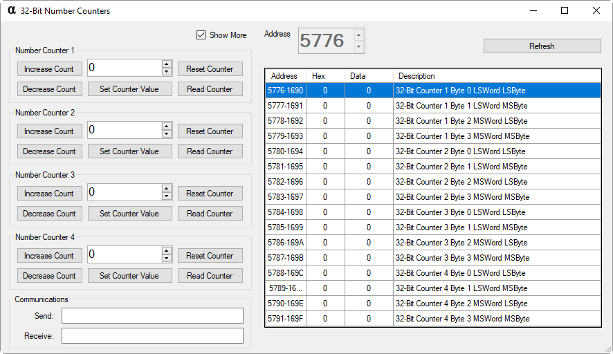
Byte 1: 0xEB - Counter Control Header
Byte 2: 0x01 - Counter Number to Control (Valid Range is 0x01 to 0x04)
Byte 3: 0x00 - Increase Selected Counter
Please use the API Calculator to Properly Encode All Commands.
This command will respond with 4 Bytes representing the updated Count value as indicated below:
Byte 1: LSB - MSByte of LSWord of a 32-Bit Word indicating the Current Count Value
Byte 2: MSB - LSByte of LSWord of a 32-Bit Word indicating the Current Count Value
Byte 3: LSB - MSByte of MSWord of a 32-Bit Word indicating the Current Count Value
Byte 4: MSB - LSByte of MSWord of a 32-Bit Word indicating the Current Count Value
Result32 = (MSWord_MSByte * 16777216) + (MSWord_LSByte * 65536) + (LSWord_MSByte * 256) + LSWord_LSByte
Library Integration: NCDLib.Enterprise.System.NumberCounters.IncreaseCounter(NCDComponent1, Counter.Value)Byte 1: 0xEB - Counter Control Header Byte 2: 0x01 - Counter Number to Control (Valid Range is 0x01 to 0x04)
Byte 3: 0x01 - Decrease Selected Counter Please use the API Calculator to Properly Encode All Commands.
This command will respond with 4 Bytes representing the updated Count value as indicated below:
Byte 1: LSB - MSByte of LSWord of a 32-Bit Word indicating the Current Count Value
Byte 2: MSB - LSByte of LSWord of a 32-Bit Word indicating the Current Count Value
Byte 3: LSB - MSByte of MSWord of a 32-Bit Word indicating the Current Count Value
Byte 4: MSB - LSByte of MSWord of a 32-Bit Word indicating the Current Count Value
Result32 = (MSWord_MSByte * 16777216) + (MSWord_LSByte * 65536) + (LSWord_MSByte * 256) + LSWord_LSByte
Library Integration: NCDLib.Enterprise.System.NumberCounters.DecreaseCounter(NCDComponent1, Counter.Value)Byte 1: 0xEB - Counter Control Header Byte 2: 0x01 - Counter Number to Control (Valid Range is 0x01 to 0x04)
Byte 3: 0x02 - Set Counter Value
Byte 4: 0x00 - LSByte of LSWord of 32-Bit Value
Byte 5: 0x00 - MSByte of LSWord of 32-Bit Value
Byte 6: 0x00 - LSByte of MSWord of 32-Bit Value
Byte 7: 0x00 - MSByte of MSWord of 32-Bit Value Please use the API Calculator to Properly Encode All Commands.
This command will respond with 4 Bytes representing the updated Count value as indicated below:
Byte 1: LSB - MSByte of LSWord of a 32-Bit Word indicating the Current Count Value
Byte 2: MSB - LSByte of LSWord of a 32-Bit Word indicating the Current Count Value
Byte 3: LSB - MSByte of MSWord of a 32-Bit Word indicating the Current Count Value
Byte 4: MSB - LSByte of MSWord of a 32-Bit Word indicating the Current Count Value
Result32 = (MSWord_MSByte * 16777216) + (MSWord_LSByte * 65536) + (LSWord_MSByte * 256) + LSWord_LSByte
Library Integration: NCDLib.Enterprise.System.NumberCounters.SetCounter(NCDComponent1, Counter.Value, Count.Value)Byte 1: 0xEB - Counter Control Header Byte 2: 0x01 - Counter Number to Control (Valid Range is 0x01 to 0x04)
Byte 3: 0x03 - Get Counter Value Please use the API Calculator to Properly Encode All Commands.
This command will respond with 4 Bytes representing the updated Count value as indicated below:
Byte 1: LSB - MSByte of LSWord of a 32-Bit Word indicating the Current Count Value
Byte 2: MSB - LSByte of LSWord of a 32-Bit Word indicating the Current Count Value
Byte 3: LSB - MSByte of MSWord of a 32-Bit Word indicating the Current Count Value
Byte 4: MSB - LSByte of MSWord of a 32-Bit Word indicating the Current Count Value
Result32 = (MSWord_MSByte * 16777216) + (MSWord_LSByte * 65536) + (LSWord_MSByte * 256) + LSWord_LSByte
Library Integration: NCDLib.Enterprise.System.NumberCounters.ReadCounter(NCDComponent1, Counter.Value)Byte 1: 0xEB - Counter Control Header Byte 2: 0x01 - Counter Number to Control (Valid Range is 0x01 to 0x04)
Byte 3: 0x04 - Reset Selected Counter Please use the API Calculator to Properly Encode All Commands.
This command will respond with 4 Bytes representing the updated Count value as indicated below:
Byte 1: LSB - MSByte of LSWord of a 32-Bit Word indicating the Current Count Value
Byte 2: MSB - LSByte of LSWord of a 32-Bit Word indicating the Current Count Value
Byte 3: LSB - MSByte of MSWord of a 32-Bit Word indicating the Current Count Value
Byte 4: MSB - LSByte of MSWord of a 32-Bit Word indicating the Current Count Value
Result32 = (MSWord_MSByte * 16777216) + (MSWord_LSByte * 65536) + (LSWord_MSByte * 256) + LSWord_LSByte
Library Integration: NCDLib.Enterprise.System.NumberCounters.ResetCounter(NCDComponent1, Counter.Value)