What is the API Calculator?
The API Calculator is used to wrap a low-level command with the necessary header and checksum required for proper communications with NCD endNode devices. If you are communicating to a wireless endNode device, you will need the destination address as printed on the outside of the endNode controller. Enter this address in Step 1 below. Next, enter a command as shown in the documentation in Step 2 (only one command at a time). This calculator will wrap your command in both NCD API and Digi 900HP-S3B API formats. You can send the calculated bytes directly to the endNode controller to utilize functions such as relay control, sensor readings, analog to digital conversion, GPIO monitoring and control, as well as a wide variety of PWM and display control operations. Since endNode devices are essentially intelligent serial to I2C converters, NCD endNode devices offer an unlimited hardware upgrade path. As accessory devices are released, endNode controller will grow in capabilities without the need for firmware upgrades. Please note that all values are in HEX below.
Step 1: Wireless Destination Address (if applicable)
Enter the Wireless Destination Address in Hex as Printed on the Outside of the Device.
Please Note: Use 00 13 A2 00 00 00 00 FF to broadcast a command to all endNodes.
Step 2: Enter a Command
Command in Hex: endNode Devices Accept Hundreds of Commands with Options.
Please Note: default command "FE 21" is used to Test 2-Way Communications, this command works with all endNode devices.
Step 3: Calculate the API Frame
NCD API: Send these Bytes if you are using USB, Ethernet, or RS-485 Communications.
Wireless API: Send These Bytes if you are communicating to a endNode using Wireless Communications.
How Does the API Calculator Work?
The NCD API Calculator works by “Wrapping” a device command in a format the controller is capable of decoding, known as the NCD API format. In the example below, we will wrap the Hex Command: FE 21 Test 2-Way Communications to illustrate the wrapping process.
| Byte | HEX | Description |
| 1 | AA | NCD API Header Byte is Always AA |
| 2 | 02 | NCD API Number of Bytes in Command (2 Bytes for the Test 2-Way Command) |
| 3 | FE | NCD API Payload (Command Byte 1) |
| 4 | 21 | NCD API Payload (Command Byte 2) |
| 5 | 77 | NCD API Checksum (8-Bit Sum of Bytes 1, 2, 3, and 4) |
Wireless Commands
If you intend to send the same command via Wireless communications, the command will need to be wrapped with a second layer in the Digi 900HP-S3B API format. Below is a illustration of how the command is wrapped for communications over wireless.
In the example below, we will wrap the same command: AA 02 FE 21 77 Test 2-Way Communications to illustrate the wrapping process. Note the original command, FE 21 was wrapped in the NCD API Format, resulting in AA 02 FE 21 77 shown in GREEN below, now it is ready to be wrapped in Digi 900HP-S3B format.
For the purposes of this demonstration, we will want to target a particular remote device with a serial number (as printed on the device). The Destination Address of the remote device is always a unique serial number, for the purposes of this example, we will use: 00 13 A2 00 41 8C 31 A8 shown in BLUE.
The Digi 900HP-S3B Wireless API format will look like this: 7E 00 13 10 00 00 13 A2 00 41 8C 31 A8 FF FE 00 40 AA 02 FE 21 CB C1
| Byte | HEX | Description |
| 1 | 0x7E | Header Byte |
| 2 | 0x00 | Number of Bytes in Payload (MSB Value) |
| 3 | 0x13 | Number of Bytes in Payload (LSB Value) Actual Number of Bytes = (MSB x 256) + LSB Example: 0x13 = 19 Bytes in RED |
| 4 | 0x10 | Fixed Byte is always 0x10 |
| 5 | 0x00 | Fixed Byte is always 0x00 |
| 6 | 0x00 | Destination Address of this Command (As Printed on the Label of the Remote Device) |
| 7 | 0x13 | Destination Address of this Command |
| 8 | 0xA2 | Destination Address of this Command |
| 9 | 0x00 | Destination Address of this Command |
| 10 | 0x41 | Destination Address of this Command |
| 11 | 0x8C | Destination Address of this Command |
| 12 | 0x31 | Destination Address of this Command |
| 13 | 0xA8 | Destination Address of this Command |
| 14 | 0xFF | Fixed Byte is always 0xFF |
| 15 | 0xFE | Fixed Byte is always 0xFE |
| 16 | 0x00 | Fixed Byte is always 0x00 |
| 17 | 0x40 | Fixed Byte is always 0x40 |
| 18 | 0xAA | Wireless Payload: NCD API Byte 1: NCD API Frame Header |
| 19 | 0x02 | Wireless Payload: NCD API Byte 2: NCD API Payload Length |
| 20 | 0xFE | Wireless Payload: NCD API Byte 3: NCD Command Header |
| 21 | 0x21 | Wireless Payload: NCD API Byte 4: NCD Command: Test 2-Way Communications |
| 22 | 0xCB | Wireless Payload: NCD API Byte 5: NCD Checksum: 8-Bit Sum of NCD API Bytes 1-4 |
| 23 | 0xC1 | Checksum = 255 minus the 8-Bit Sum of all Bytes in RED |
How Do I Send Data to endNode Devices?
Regardless of communications technologies (Wireless, USB, Ethernet, RS-485), we use a tool called “Comm Operator”, which was designed by one of our staff members. Comm Operator makes it easy to communicate bytes of data, and a Free 30-Day trial version is available for download. Of course you can use any software that supports serial or network communications, but Comm Operator has the ability to communicate to all NCD devices, regardless of communications interface. We will demonstrate the use of Comm Operator using USB, Ethernet, and Wireless communications below, starting with USB. To get started, please download and install your Free trial version of Comm Operator from Serial Port Tool. If you prefer not to use Comm Operator, please follow the steps shown below as important communication settings will be discussed that applies to all programming languages and communication tools.
USB Communications to endNode Devices
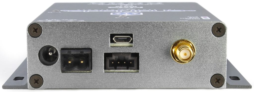
The USB Micro Port (Top Center Connector) is used for direct USB Communications to the endNode controller. The default operating baud rate is 115.2K. Use this Port for Accessing endNode functions as well as device Configuration.
Ethernet Communications to endNode Devices
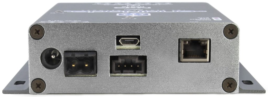
The Ethernet Port (Right Connector) is used for Communications to the endNode controller via TCP/IP Communications. endNode devices broadcast their IP Address on UDP Port 13,000 for easy device discovery. Initial Setup will require a DHCP Router. endNode does support Static IP Addresses.
Wireless Communications to endNode Devices
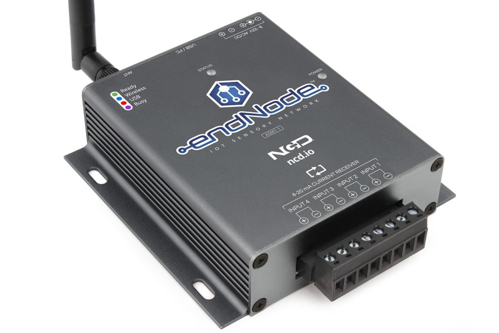
Communicate to endNodes using a long-range wireless Mesh Network with communication distances up to 2 Miles Line of Sight. endNodes can communicate to multiple modems simultaneously, allowing many computers access to a single endNode device.
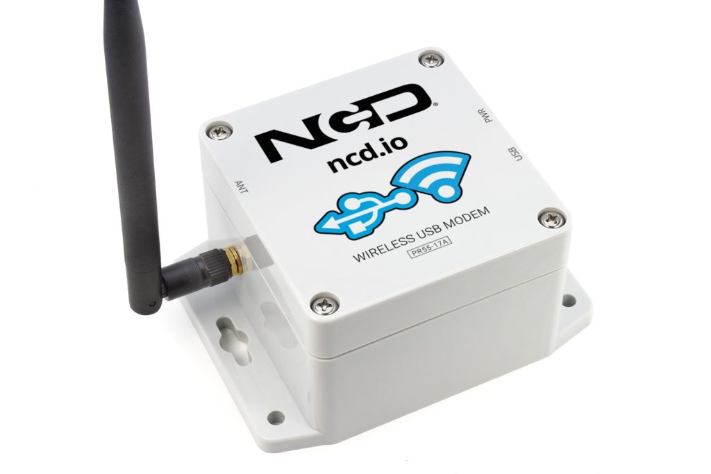


Plug the USB Modem into the USB Port of your Computer and Talk to endNode devices up to 2 Miles Away. Target Multiple endNode devices from a single modem.
Plug the Ethernet Modem into your Router and Talk to endNode devices up to 2 Miles Away. Target Multiple endNode devices from a single modem.
Use your RS-485 Equipped PLC to Communicate to our RS-485 Modem and Access Remote endNodes in an industrial environment.