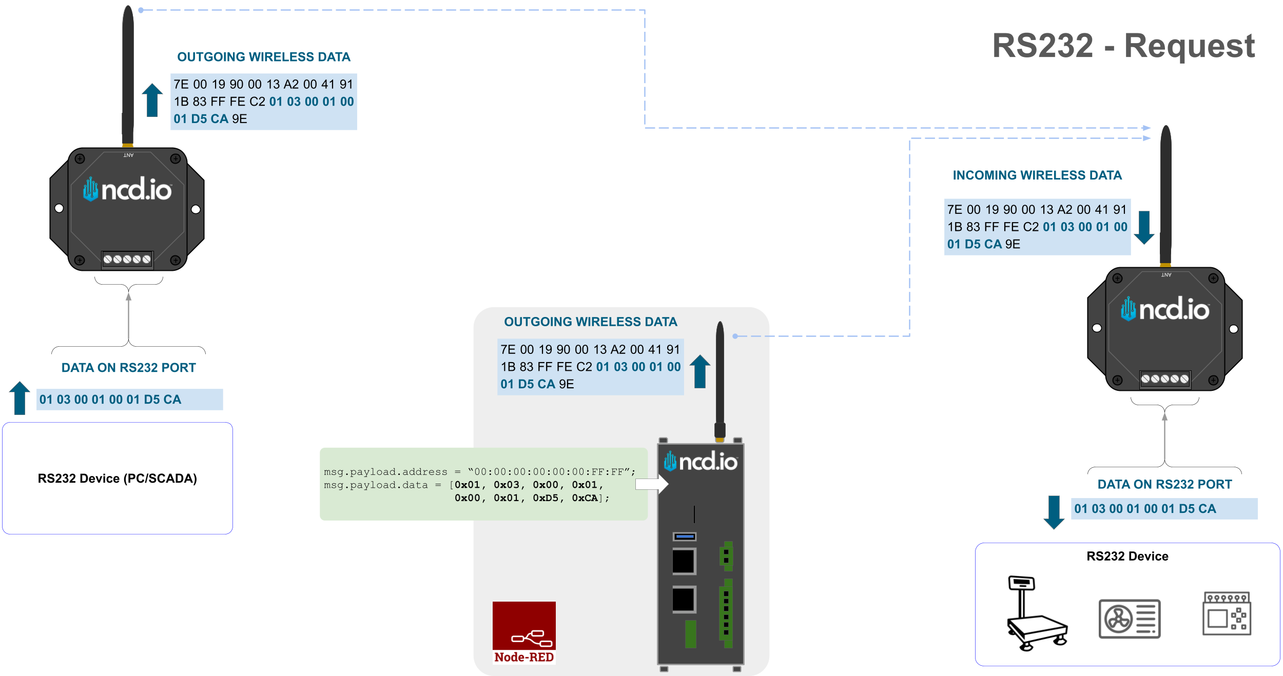
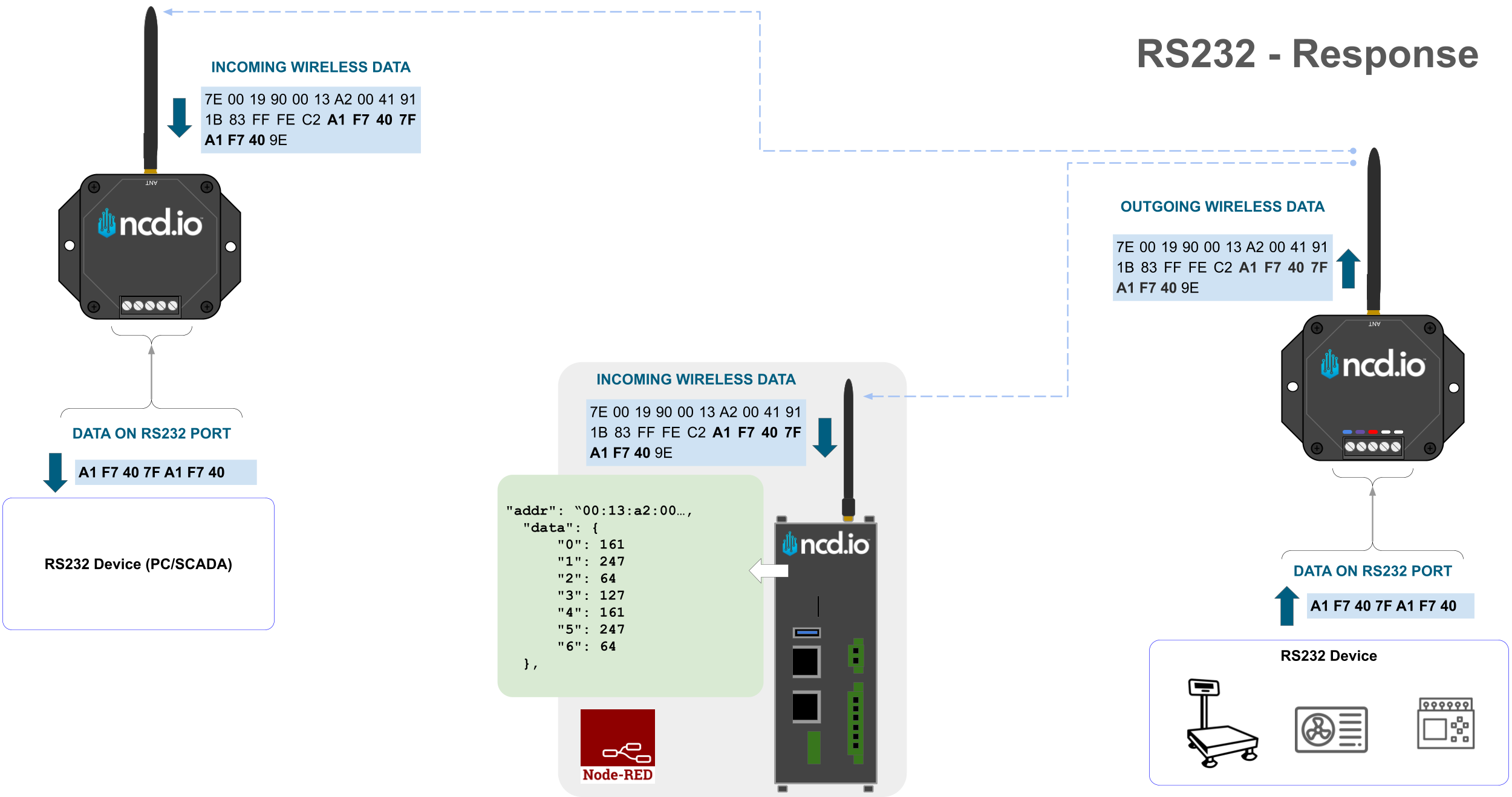
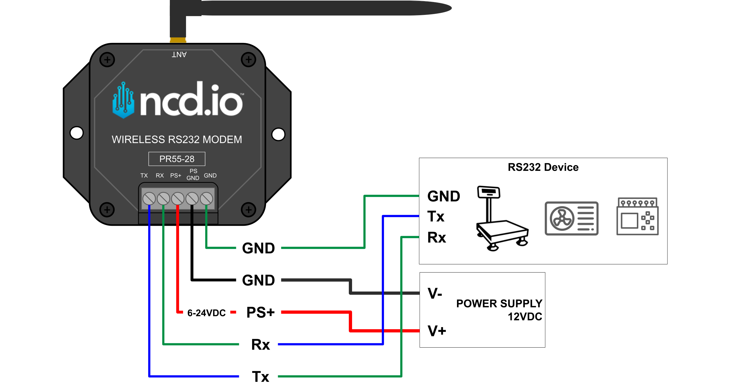
This guide demonstrates how to use the NCD Wireless RS232 Modem to request and receive data from an external RS232 device via Node-RED. By implementing a custom Node-RED flow, you can easily build and transmit RS232 polling commands. Once triggered, the modem sends the command to your RS232 device, which then processes the request and responds with the appropriate data.
NoteThis guide assumes your specific RS232 device—such as a scale or PLC—supports standard request/polling commands
System Architecture Overview
RS232 Request Example
RS232 Response Example
Prerequisites
Before you begin, ensure you have the following hardware and software ready:
Tools: Comm Operator or a standard Serial Terminal (recommended for debugging).
NCD RS232 Modem Configuration
To establish successful communication, the RS232 serial settings on your modem must match the settings of your target RS232 device. Node-RED allows you to configure these settings directly, including:
Baud Rate
Data Bits
Stop Bits
Parity
Timeout
Auto Address Timeout
Default Modem Settings: If your RS232 device matches the default configuration below, you do not need to reconfigure the modem:
Baud Rate: 9600
Data Bits: 8
Stop Bits: 1
Parity: None
You can configure this device “On The Fly,” which allows you to update the modem’s parameters without physically putting the sensor into configuration mode. Refer to the standard Node-RED device configuration guide for more details on this process.
We have created a ready-to-use Node-RED flow that transmits RS232 commands from Node-RED to the NCD RS232 Modem’s output. Follow these steps to import, configure, and deploy the flow:
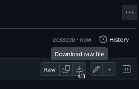
Step 1: On a local machine with internet access, navigate to the NCD GitHub repository. Click the Download Raw File button to save the .json flow example to your computer.
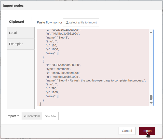
Step 2: Open the Node-RED editor running on your NCD Gateway. Click the main menu (hamburger icon) in the top right corner and select Import. Click the Select a file to import button, choose the .json file downloaded in Step 1, and click Import.
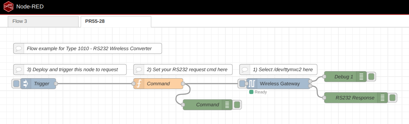
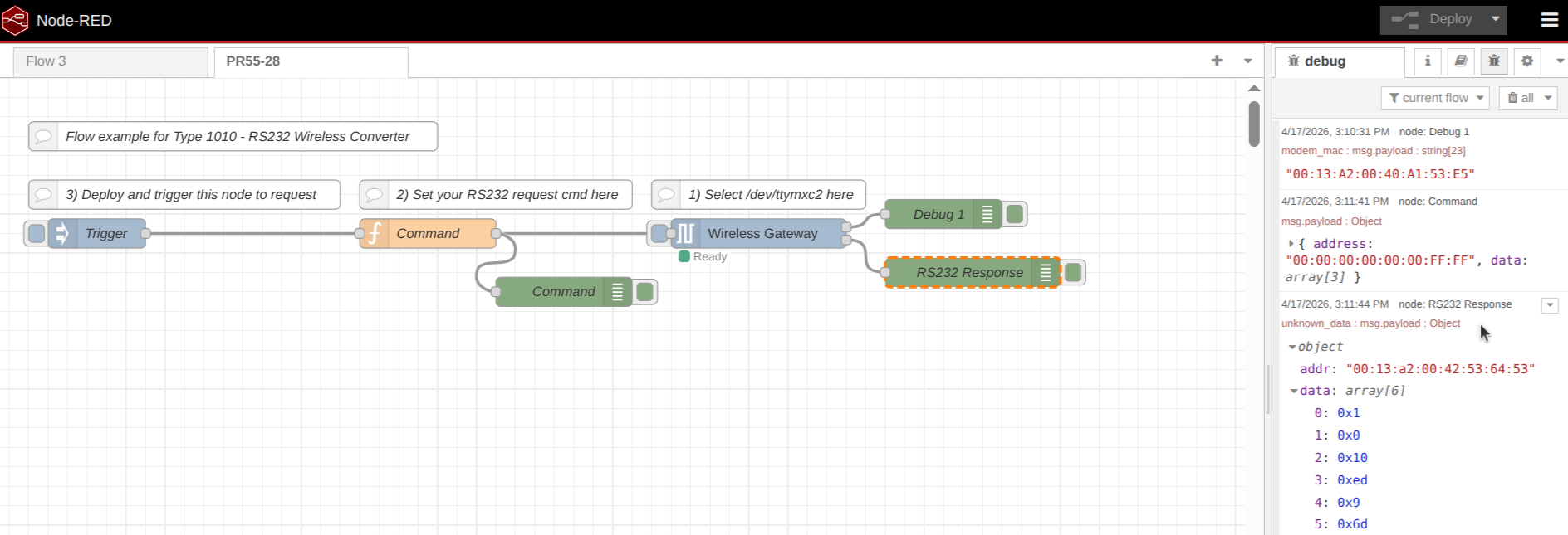
Step 3: The imported flow will appear in a new workspace tab titled PR55-28. Here is a breakdown of how the nodes function:
Click to Expand
Trigger Node: Allows you to manually trigger the RS232 command flow. Clicking the embedded button on the left side of the node fires the complete flow. (This node can also be automated; see the “Automated Polling” section below).
Command (Function) Node: This node builds the RS232 command payload. You will write the specific hexadecimal command you want to transmit to your end device here.
Wireless Gateway Node: Part of the NCD Library, these nodes bridge communication between Node-RED and the Gateway’s wireless module. The first one transmits your command, while the second one receives the incoming data.
Debug 1 Node: Displays standard NCD sensor diagnostic data in the Node-RED debug sidebar.
RS232 Response (Debug) Node: Connected to the receiving Wireless Gateway node, this displays the actual RS232 payload response from your end device in the debug sidebar.
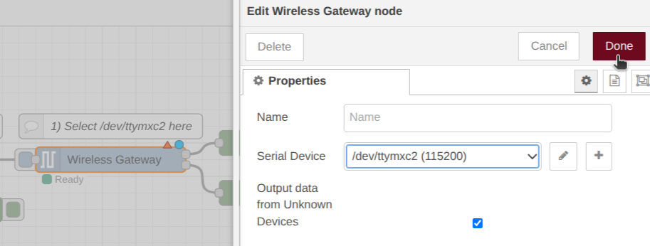
Step 4: Configure the serial port on the Wireless Gateway node. Double-click the node, select /dev/ttymxc2 from the drop-down menu, and click Done.
Click to Expand
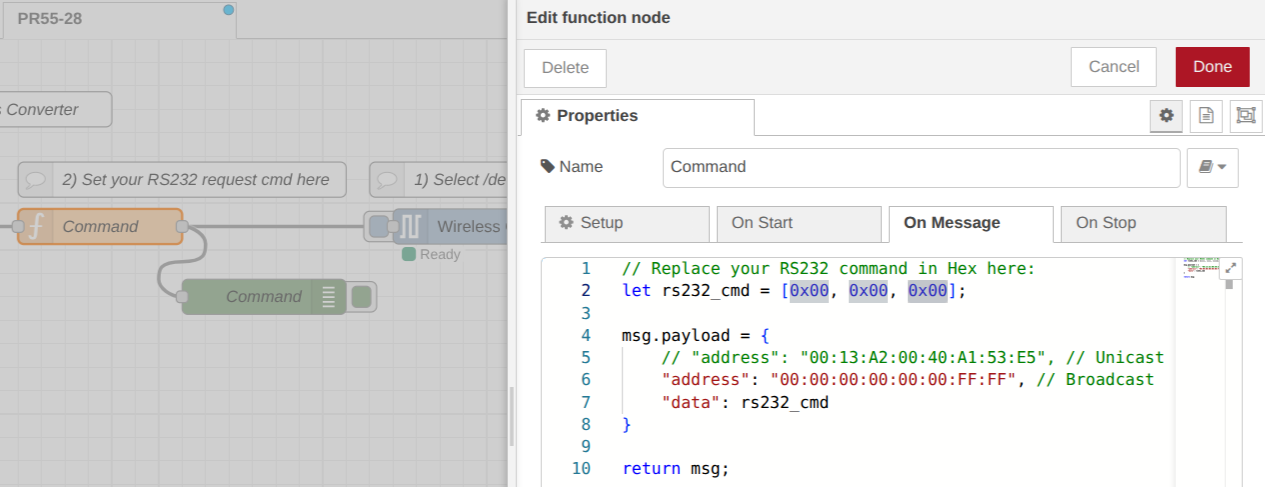
Step 5: Customize your RS232 command. Double-click the Command node to open the JavaScript editor. Update the rs232_cmd array with the hexadecimal values required by your specific RS232 device. You can adjust the array size as needed.
Click to Expand
Here are a few format examples:
					// Base template: Replace with your specific RS232 command array
let rs232_cmd = [0x00, 0x00, 0x00];

// Example 1:
let rs232_cmd = [0x51, 0x0D, 0x0A, 0x00];

// Example 2:
let rs232_cmd = [0x01, 0x51, 0x02, 0x0D, 0x0A, 0x00];
Step 6: Once your custom command is entered, click Done. Finally, click the Deploy button in the top right corner of Node-RED to save and apply your changes. Your flow is now ready to transmit.
Optional: Testing the Command Output
Before connecting to your final industrial equipment, it is best practice to verify that the modem is outputting the correct command.
Testing Setup:
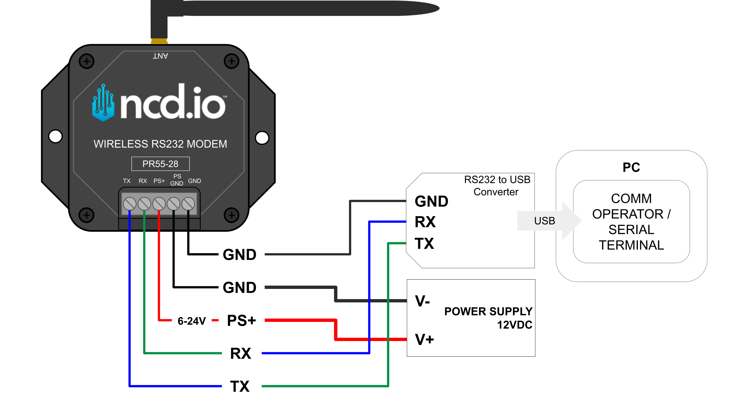
Connect an RS232-to-USB converter to the NCD RS232 Modem’s output terminals.
Plug the USB into your PC and open a Serial Terminal (Comm Operator).
Ensure the Comm Operator/Serial Terminal settings (baud rate, parity, stop bits) exactly match the NCD RS232 Modem’s settings.
Click to Expand
Running the Test: With the serial monitor open on your PC, click the square button on the Node-RED Trigger node. You should see your programmed hexadecimal command appear in your PC’s serial monitor exactly as you typed it.
Final Implementation
Once you have verified the data output, disconnect the USB converter and wire the NCD RS232 Modem directly to your target RS232 device (e.g., scale or PLC).
Trigger the flow again from Node-RED. The modem will poll the device, and you should instantly see the device’s reply populate in the Node-RED debug sidebar.
Click to Expand
Automated Polling (Optional)
If your application requires continuous data logging at regular intervals, you can automate the request.
Double-click the Trigger node.
Check the box labeled Inject once after and set a brief delay (e.g., 0.1 seconds) so the flow initializes immediately upon deployment.
In the Repeat drop-down menu, select interval.
Define your desired polling frequency (e.g., every 5 seconds, minutes, or hours).
Click Done, then click Deploy.
Node-RED will now automatically poll your RS232 device at the defined interval, providing a steady stream of data for your dashboard or integration project.