Table of Contents
Pre-requisites
This guide assumes you are somewhat familiar with TagoIO and you have registered with the platform already. If you have not you can do this via the TagoIO page.
Another pre-requisite is that you have a Machine Uptime Monitor and an Edge Gateway and they are connected and working. You can refer to the Sensor Manual if you have issues setting it up.
Creating the device in TagoIO
The way this integration works is directly via MQTT, in a way the Machine Uptime Monitor itself does not directly connect to TagoIO, rather it sends its data to the Gateway that forwards it to TagoIO. We still need to set up the sensor in the platform, but it will be as a generic MQTT device since this is what the Gateway is seen by the platform as.
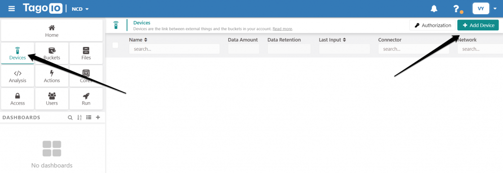
In your TagoIO panel go to the Devices section and click on the Add Device button.
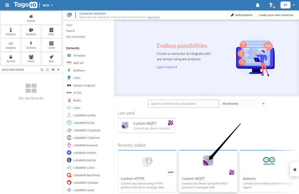
Select Custom MQTT for the Connector type (a connector is how TagoIO identifies different protocols devices operate via).
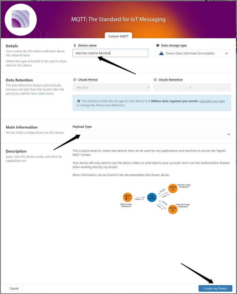
Give your device a name and change the Payload Type field to be empty as we will be dealing with it later via the Payload Parser. Press the Create my Device button and your device will be created.
Now that we have our device it will pop up in the panel, click on it and you will get to its main screen where we need to set up several parameters in order to properly connect the NCD sensor and the platform.
Creating tokens
I order to connect and authenticate a device via MQTT we require credentials (username and password for the MQTT node in Node-RED), which in the case of TagoIO are two tokens:
- Device token
- Profile token
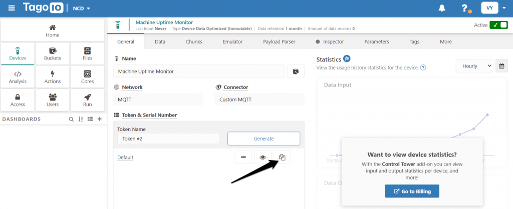
Let’s start with the device token, as it is easier to get to, it being on the main device page (refer to the image below). You can simply press on the button and it will be copied. Make sure you save it somewhere for later.
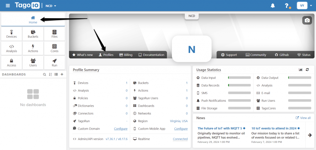
The next step is getting the Profile token, go back to the Home page and navigate to Profiles.
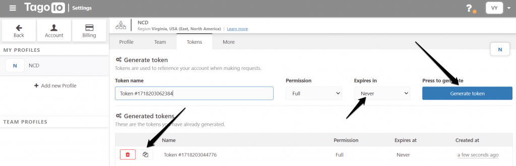
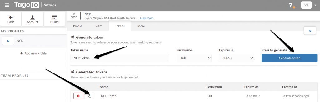
Navigate to the Tokens subpage, fill in the Token name and generate one via the blue button. It will appear in the table where you can copy if the same way you did the Device token and save it up for the next step.
Configure the MQTT client in Node-RED (Edge gateway).
Navigate to the Tokens subpage, fill in the Token name and generate one via the blue button. It will appear in the table where you can copy if the same way you did the Device token and save it up for the next step.
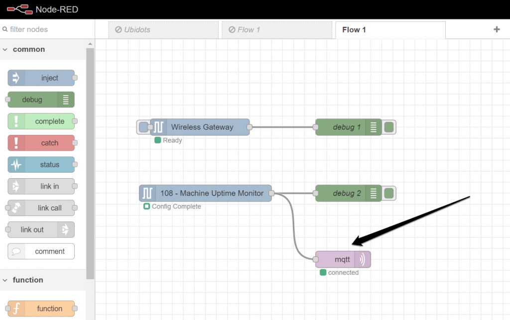
Add a MQTT node in the Gateway flow and double click on it so its configuration window pops up. We need to set up a few parameters on this end as well.
Enter the following in the Connection tab:
Server: mqtt.tago.io
Port: 8883
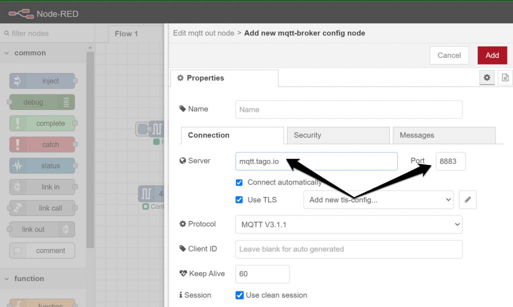
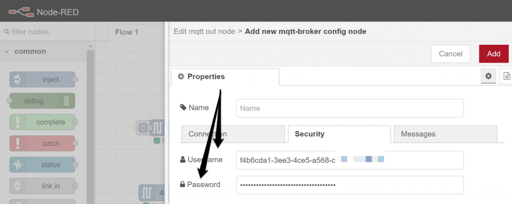
Leave the rest with the default values and move to the Security tab. This is the time for the token from the previous step, where:
Username: Profile token
Password: Device token
Finish up and your Edge Gateway should now be connected to TagoIO.
Processing the data from the current sensor
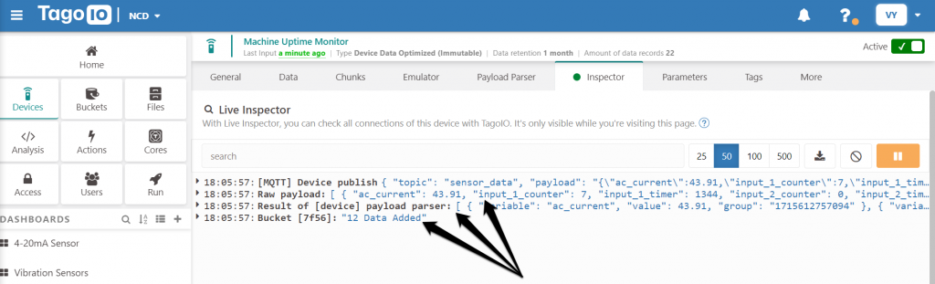
Now that we have the sensor sending to the gateway and the gateway sending to TagoIO we can check the incoming data in real time in the Inspector tab of the Device.
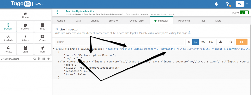
As you can see data is being published via the TagoIO MQTT broker, where we have set the topic to be Machine Uptime Monitor (you can name it in the Node-RED MQTT block topic field any way you like) and the payload itself for the sensor.
In order to process the data an make it suitable and available for the platform (storage and visualization) two things need to happened.
- Data parsing – convert the incoming JSON into a TagoIO JSON (they have a specific structure)
- Action trigger – we need to trigger an action upon reception of a data packet that will take the parsed value and insert it into a Bucket (the database structure TagoIO uses to store data).
Payload Parser
Click on the Payload parser section in the Device panel. This will take you to a screen where you can enable or disable the functionality and write your own Decoder to parse the data. You can also select from a set of pre-coded examples, which is what we will be doing here.
Enable the Parser via the toggle and select the Convert Raw JSON to TagoIO JSON from the drop-down menu (image below for reference).
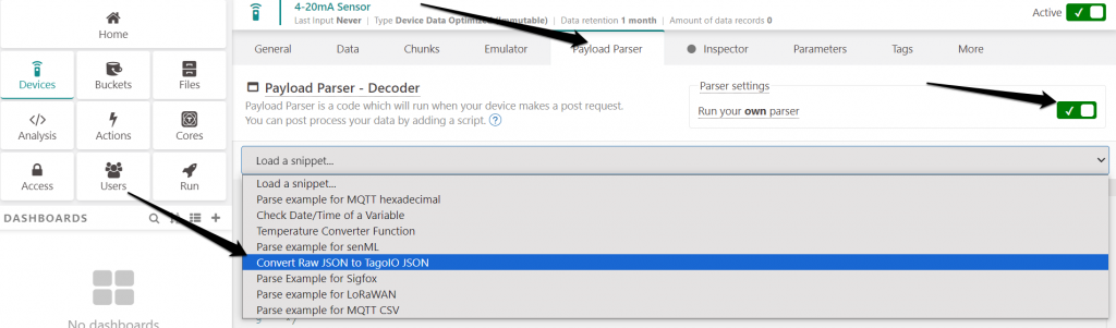
Save your settings and your parser should be activate, the incoming data will be reshaped in a format suitable to be ingested by TagoIO.
Action
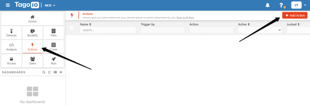
Navigate away from the Device section and into the Actions one. This will bring up a list of configured actions where you can add one (yours should be empty at this point).
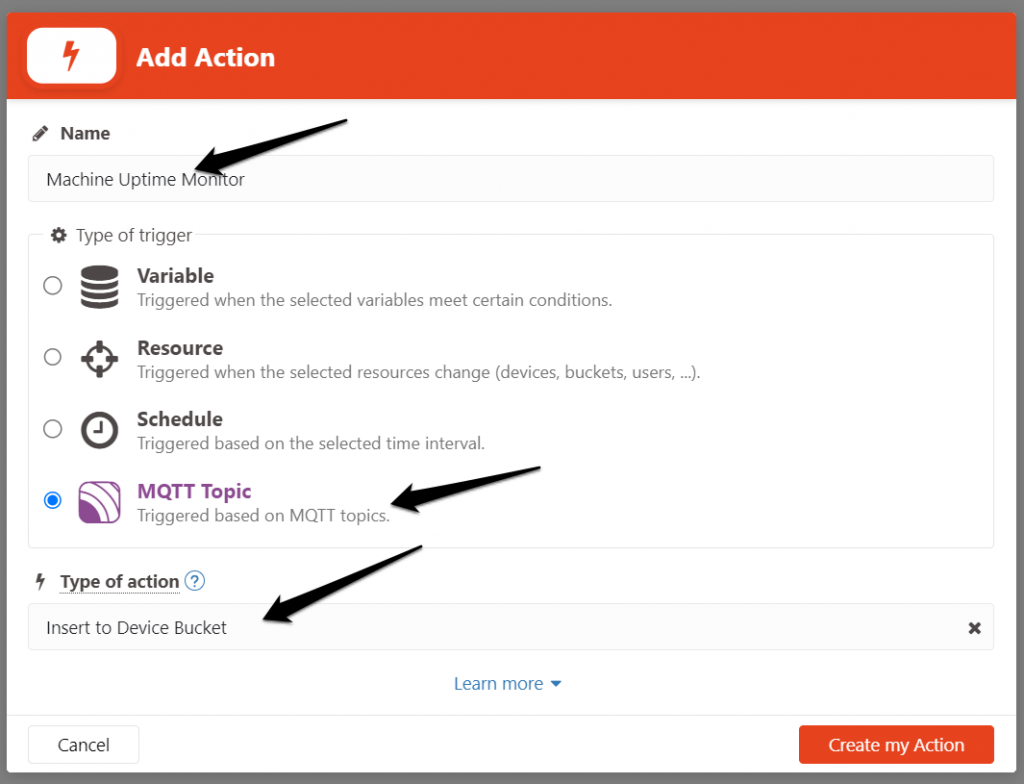
Give the action an appropriate name and select the trigger to be MQTT topic. This way when data is published on the MQTT topic it will trigger the action in response.
Select the Type of action to be Insert to Device Bucket and create the action.
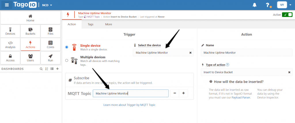
On the main Action screen, we still need to set up the MQTT topic to look at for incoming data.
Select the device this applies to, in our case the Machine Uptime Monitor (we are using a single device example).
Enter sensor_data in the MQTT Topic box, this will subscribe the Action to it. Now a packet incoming on this topic will trigger the action to insert the data into the Device bucket, and since it has been properly parsed already it will be stored (it would produce an error if it were not in the right format.
If you get back to the Inspector and wait for an incoming packet you will see additional where the data is parsed and inserted into the bucket (3 parameters are stored, the two measurements and the metadata).
This is it; the hard part is done; the entire communication chain has been completed and it is working.
To sum it up in the end:
- The Machine Uptime Monitor is taking readings and sending them to the Gateway via DigiMesh wirelessly.
- The Gateway is receiving the radio packets and its Node-RED instance is processing it, so it can forward it to TagoIO via MQTT
- The TagoIO MQTT broker is receiving the data and publishing it to a topic.
- The Parser is reformatting the data so it can be manipulated.
- An action is triggered that automatically takes the parsed data and dumps it into a bucket to be store.
Now comes the fun part, taking the readings and visualizing them in a nice dashboard.
Dashboard
Simply navigate to the Dashboard are and press on the “Plus” icon, it is accessible right from any screen (Device, Action, etc.)
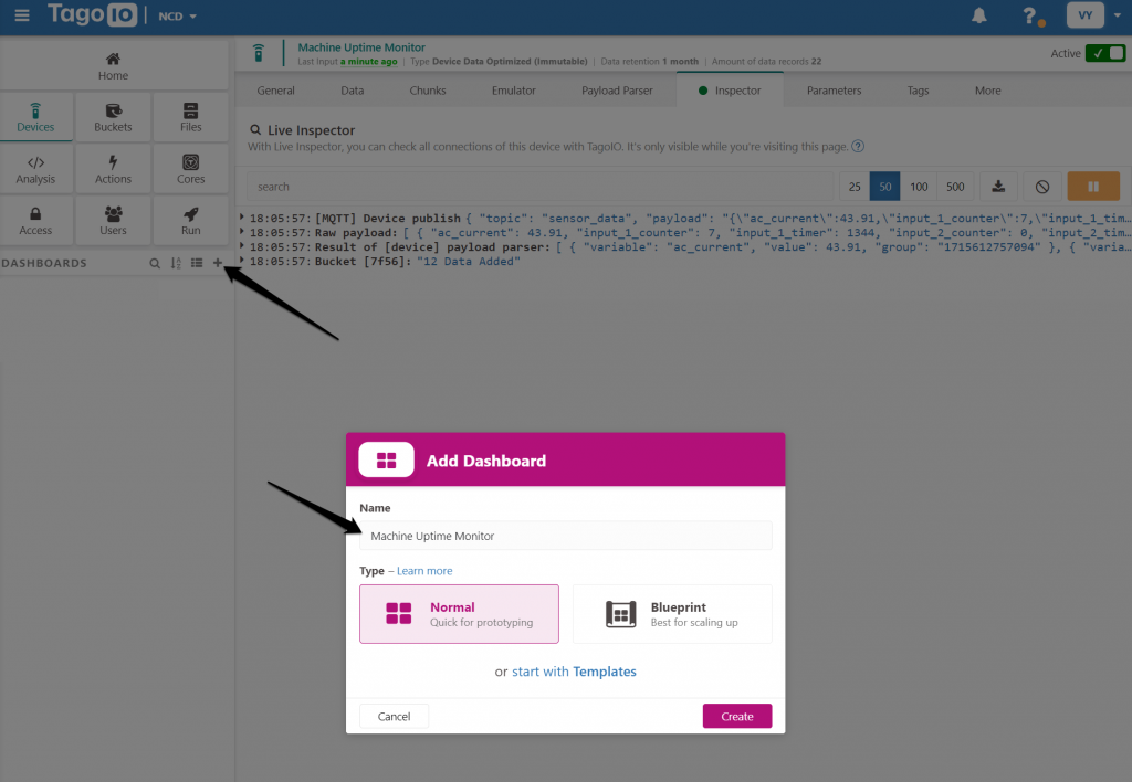
Give you Dashboard an appropriate name. leave the default Normal type and create it. It starts as a clean slate and you need to add Widgets in order to visualize a parameter or several.
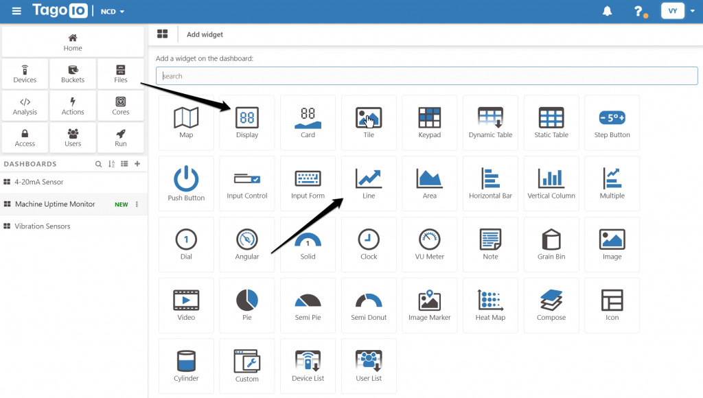
We are going to add 3 different Widgets that should add meaningful functionality to the Dashboard for this particular sensor.
- A Display to show the values for the 11 parameters of the device in a number format.
- A Line chart to show how the Current changed over time.
Refer to the following image so you know exactly which widget is which, as there is quite a variety.
Display
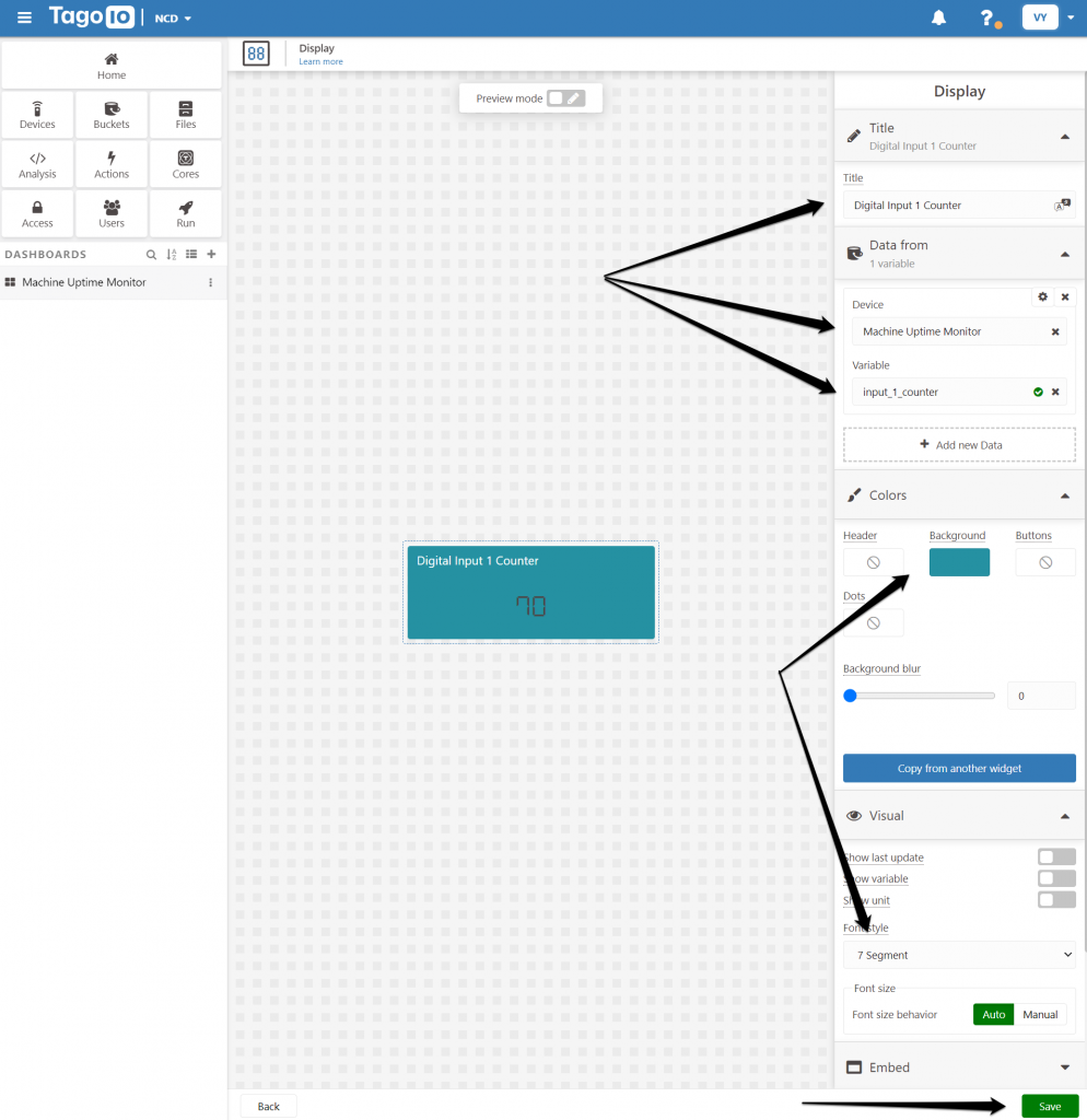
An example is going to be given for one of the parameters, in order to configure the widget properly. The remaining 10 can be configured in the same way, you just need to change the Title and Select the Variable anew. A good method would be to clone the one we are going to instruct you on configuring first (via the Duplicate menu you can access at the top right corner via the dots icon).
Start by entering a Title (for the first parameter it would be Digital Input 1 Counter).
Select the Device -> Machine Uptime Monitor from the drop down menu
Select the Variable -> input_1_counter
Select a Colour (optional).
Select your Visual style (optional).
Save and you are done.
Refer to the image below for the location of the aforementioned field.
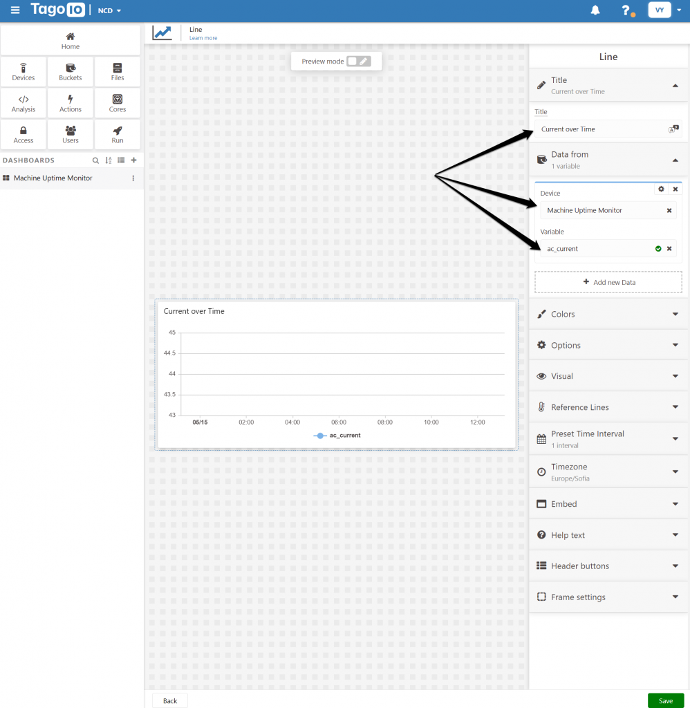
Line Chart
As is for the rest of the widgets you need to select:
Device -> Machine Uptime Monitor (this remains the same for every widget)
Variable -> ac_current
You can leave the rest of the values with their default values. Save and you will get a graph of the measured current in mA and how it changes over time.
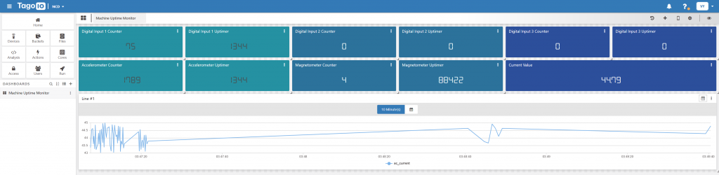
Complete dashboard
The image below represents a version of the complete dashboard displaying all parameters, use it as reference for their naming and values. You can rearrange and style the as you wish (change the colour, display format, etc.)
You can add or remove a widget any time if you want to display fewer or more parameters depending on your use -case scenario.