- Applications & Use-cases
- Detailed Specifications of NCD's Uptime Monitor
- Getting started
- Node-RED Dashboard
- Advanced Configuration
- Example Configuration Commands
- Read Sleep Duration
- Set Sensor Node ID and Sleep Duration
- Read Sensor Network ID
- Set Wireless Sensor Network ID
- Read Sensor Destination Address
- Set Sensor Destination Address
- Set Sensor Destination to Broadcast
- Read Wireless Sensor Transmission Power Level
- Read Wireless Sensor Retries
- Set Wireless Sensor number of Retries
- Set Wireless Sensor Encryption Key
- Troubleshooting
- Appendix A - Configuration Commands
- Appendix B - Command Acknowledgement Data
- Appendix C - Application Specific Commands
- Appendix D - Error Code Descriptions
- Appendix E - Frame Checksum Calculation
Features
- Industrial Grade Machine Uptime Monitoring
- Measure Production Uptime
- Measure Number of Cycles
- Dry Contact Closure Input
- Wet Contact Closure Input
- Acceleration Motion Detection based Uptime calculator
- Magnetic Field Detection based Uptime calculator
- Current-based Uptime calculator
- Encrypted Communication with 2 Mile Wireless Range
- Operating Temperature Range -40 to +60 °C
- Humidity Range 0-90%
- Wall-Mounted or Magnet Mounted IP65 Rated Enclosure
- For Indoor and Outdoor Use
- Many Gateway and Modem Options Available
Table of Contents
Applications & Use-cases
This sensor is a versatile device that brings a new level of precision and reliability to uptime monitoring across a wide range of industrial applications. Its unique combination of digital and analog sensing technologies, coupled with robust wireless communication and a durable enclosure, makes it an ideal choice for diverse environments and challenging operational conditions.
Applications
Manufacturing Plants
In manufacturing settings, the ability to monitor machine uptime accurately is crucial for minimizing downtime and maximizing productivity. The sensor’s multi-sensor functionality enables detailed tracking of production uptime and cycle counts. Its dry and wet contact closure inputs, along with current-based, acceleration motion detection, and magnetic field detection-based uptime calculators, provide a comprehensive view of machine performance. This ensures manufacturing plants can swiftly identify and address issues, maintain high operational standards, and optimize production schedules.
Automotive Production Lines
Automotive manufacturing demands high precision and efficiency, where any interruption can lead to significant financial losses. The Machine Uptime sensor’s IP65 rating and ability to operate in extreme temperatures (-40 to +60 °C) and humidity (0-90%) conditions make it suitable for the rigorous demands of automotive production lines. Its real-time monitoring capabilities allow for immediate detection of performance deviations, facilitating rapid response to prevent downtime and ensure continuous production flow.
Food Processing Facilities
In the food processing industry, hygiene and safety are paramount. The sensor’s wall-mounted or magnet-mounted IP65 rated enclosure ensures it can withstand the wet and variable temperature environments typical in food processing plants without compromising performance. Moreover, its versatile connectivity options support adherence to strict quality and safety standards by enabling seamless data integration with existing quality management systems.
Chemical and Pharmaceutical Industries
For chemical and pharmaceutical manufacturing, maintaining consistent operational conditions is critical to product quality and compliance with regulatory standards. The Machine Uptime sensor’s encrypted communication and its ability to monitor machinery in real-time provide an extra layer of security and compliance assurance. The sensor’s accurate detection capabilities, including current-based and magnetic field-based measurements, ensure precise monitoring of sensitive production processes, aiding in the early identification of equipment malfunctions that could affect product quality or worker safety.
Mining and Heavy Machinery Operation
The rugged design of the Machine Uptime sensor, combined with its long-range wireless communication capabilities (up to 2 miles), makes it exceptionally well-suited for the harsh and remote environments of mining and heavy machinery operations. Its battery-powered operation allows for easy installation in locations where power sources are not readily available, ensuring continuous monitoring of equipment uptime. This is critical for identifying potential equipment failures before they occur, reducing costly unplanned downtime and enhancing operational efficiency in these industries.
Use-cases
Overall Equipment Effectiveness (OEE)
OEE is a critical metric in manufacturing that evaluates equipment performance by combining availability, performance, and quality factors. In IoT-enabled environments, OEE is enhanced through real-time data collection and analysis, facilitating predictive maintenance and process optimization. IoT devices monitor equipment to automatically calculate OEE scores, predict failures, and identify inefficiencies, enabling proactive adjustments and informed decision-making.

Machine Utilization
Machine utilization measures the effectiveness of industrial equipment by tracking the proportion of time a machine is actively operating against its available time. Enhanced by IoT technology, machine utilization monitoring allows for real-time data collection, enabling more accurate and dynamic assessments of machine performance. IoT sensors gather operational data, helping to pinpoint underutilization issues, streamline production processes, and reduce downtime through timely interventions.

Productivity Measurement
Productivity measurement in industrial settings quantifies the efficiency and output of manufacturing processes. Integrating IoT technology enables real-time tracking and analytics, improving the accuracy and responsiveness of productivity assessments. By collecting data directly from production lines through IoT sensors, companies can immediately detect productivity fluctuations, analyze performance trends, and identify areas needing improvement.

Downtime Tracking
Downtime tracking in manufacturing is crucial for identifying and minimizing periods when equipment is not operational. Enhanced by IoT technology, downtime tracking becomes more precise and automated, allowing for the continuous monitoring of equipment status. IoT sensors can immediately detect when machines halt production and diagnose potential causes, such as mechanical failures or software issues.

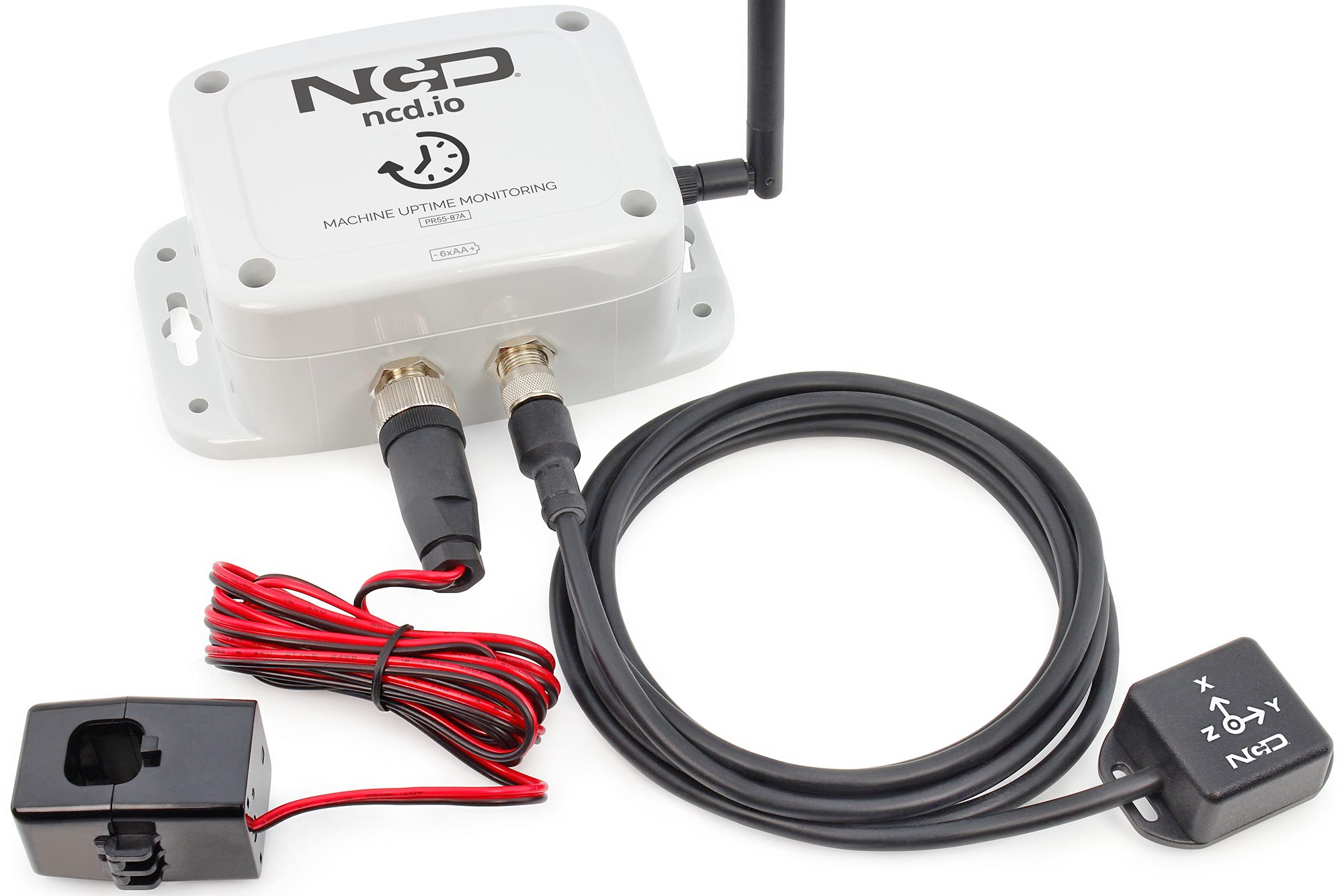
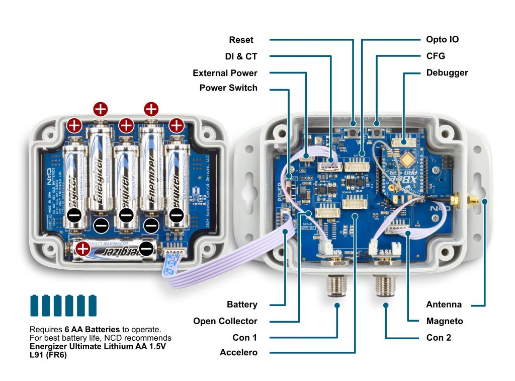
Detailed Specifications of NCD's Uptime Monitor
Device Overview
Status LED
The Status LED is used to indicate errors or other sensor diagnostics.
LED blinks once – Message was sent successfully and no error in last sensor read as well in data transmission.
LED blinks twice and then one more time – Message was sent successfully but there was an error in last sensor read.
LED blinks thrice – MCU is having issue communicating with the radio module.
Power Requirements and Expected Battery Life
Power Requirements
This Sensor has two power options:
- Powered by AA batteries (NCD recommends Energizer L91 batteries)
- External power supply (5-12 V DC) Current Requirement 250 mA
Note: The L91 Batteries are non-rechargeable Li-Ion batteries.
While changing the batteries:
- Turn off the sensor
- Only use new L91 batteries
- Checkout the polarity marking on the battery holder and batteries
- Replace all six batteries with new L91 batteries. Do not mix old and new batteries
- Batteries should not be replaced in fire-risky areas
- Do NOT install rechargeable batteries
Note: If these Devices are being used with photo eye or any other sensors needing power, use an external power supply.
Expected Battery Life
| Specifications | Minimum | Nominal | Maximum | Notes |
|---|---|---|---|---|
| Batteries | 2 | 6 | 6 | May be Powered by 2 or 4 AA Batteries |
| Battery Life 1 TPD (Transmissions per Day) | 10 Years | Estimation is based on a 30 minute interval | ||
| Battery Life 12 TPD (Transmissions per Day) | 8 Years | Estimation is based on a 30 minute interval | ||
| Battery Life 24 TPD (Transmissions per Day) | 5 Year | Estimation is based on a 30 minute interval | ||
| Battery Life 96 TPD (Transmissions per Day) | 3 Year | Estimation is based on a 30 minute interval |
Most NCD IoT Sensors are rated for 300,000 to 500,000 transmissions until the batteries become so weak they are unreliable. You could spread these transmissions out over a 10 year period and send 50,000 transmissions per year. This would allow up to 136 transmissions per day, or about 5 transmissions per hour (for a 500K sensor, or 3 per hour for 300K sensor). If you only need the batteries to last 3 years, you could send 166,666 transmissions per year, or about 456 transmissions per day (about 19 transmissions per hour for a 500K sensor). As you can see, battery life is really up to you. By altering advanced settings in the NCD IoT sensor, you have control over longevity. Please note the 500,000 transmission rating is for premium alkaline batteries. NCD ships all sensors with premium Lithium batteries, which include a ultra-wide temperature range that typically lasts in excess of 600,000 transmissions for some sensor types. These batteries weigh less than half of alkalines, and they work in the freezer! A word of caution though, putting a sensor in configuration mode will drain the batteries very quickly. It’s important to configure your sensors and exit configuration mode as soon as possible or use a external power supply during configuration (if supported by the sensor). The table below indicates how many Transmissions Per Hour (TPH) your can expect from different sensors over a lifespan of up to 10 years.
The Truth About Battery Life
Under the best of circumstances, the best non-rechargeable batteries commonly available today are limited to a 10 year non-working shelf life in a room temperature environment. Factors such as actual usage, temperature, and humidity will impact the working life. Be wary of any battery claims in excess of 10 years, as this would only apply to the most exotic and expensive batteries that are not commonly available. Also note that most battery chemistries are not rated for use in extreme temperatures. NCD only uses the best Non-Rechargeable Lithium batteries available today, which are also rated for use in extreme temperatures and have been tested by our customers in light radioactive environments. Lithium batteries offer a 10 year maximum expected shelf life due to limitations of battery technology. NCD will never rate sensor life beyond the rated shelf life of the best batteries available today, which is currently 10 years.
Printed Circuit Board Specifications
| Parameter | Minimum | Nominal | Maximum | Notes |
|---|---|---|---|---|
| Trace Width | 0.007 inch | 0.012 inch | 0.25 inch | Trace Width depends on the Trace Type |
| Layer Count | 2L - Rigid | Top and Bottom Layer | ||
| Material Type | FR-4 TG170 | FR-4 TG170 | FR-4 TG180 | |
| Surface Finish | ENIG 2u" | |||
| IPC Standard | IPC CLASS 2 | |||
| Finished Copper Foil | 1.0/1.0 OZ | |||
| Finished Thickness | 0.062 inc | |||
| Fine line <4.0/4.0mil | No | |||
| Blind & Burried Vias | No | |||
| Non-Conductive Resin | No | |||
| Conductive Resin | No |
Mechanical Drawing
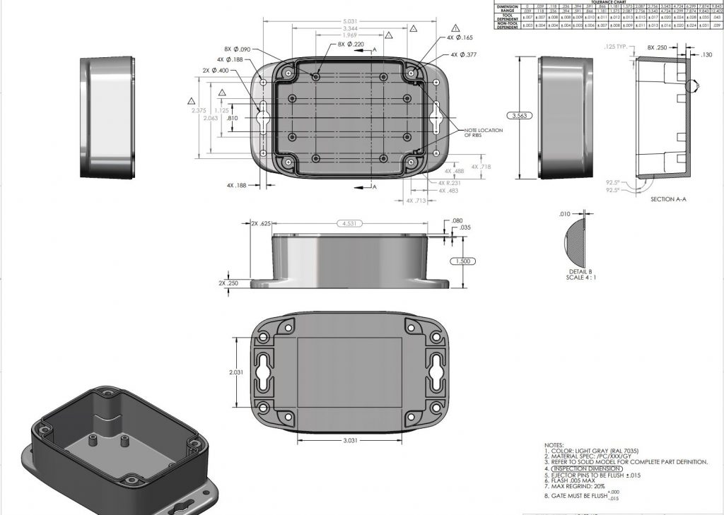
Sensor Specifications
| Specifications | Minimum | Nominal | Maximum | Notes |
|---|---|---|---|---|
| Width | 3.54" | |||
| Length | 4.52" | |||
| Height | 2.16" | |||
| Enclosure Rating | IP65, NEMA 1,2,4,4X,12,13, UL-508 | |||
| Temperature Rating | -40° C | 23° C | 85° C | Component Rating |
| Tested Temperature | 0° C | 23° C | 40° C | As Tested by NCD Staff |
| Probe Operating Temperature | -40° C | 23° C | 85° C | As Tested by NCD Staff |
| Inputs | Digital, Acceleration, Magnetic, Current | |||
| Opto-input Voltage | 3.3 V | 24V | ||
| Reporting interval | 5 seconds | 600 seconds | 16777215 seconds | How often data is transmitted wirelessly |
| Range of counter values | 1 | 4294967295 | The maximum number of events the sensor can count to | |
| CT Current | 1.5% FS | FS | Minimum current read by the CT. CT range 100 to 1000Amp |
Probes Specifications
There are 4 types of probes: Bare wire for digital inputs, Current sensor, Accelerometer, and Magnetometer.
Digital Inputs
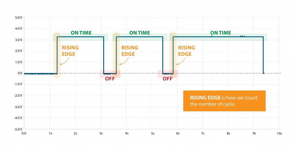
The Industrial Digital Input and Sensor Reader is a compact and robust device tailored to interpret signals from various digital inputs and sensors prevalent in industrial settings, including brake sensors, photo reflectors, and on/off signals. With high accuracy and reliability, it offers real-time data acquisition and monitoring, seamlessly integrating into existing industrial automation systems. Its user-friendly interface and flexible configuration options ensure easy setup and compatibility with diverse applications, enhancing operational efficiency, equipment reliability, and production optimization. Ideal for conveyor systems, packaging machinery, and robotic systems, it empowers industrial operators with streamlined data interpretation and control capabilities, minimizing downtime and maximizing productivity.
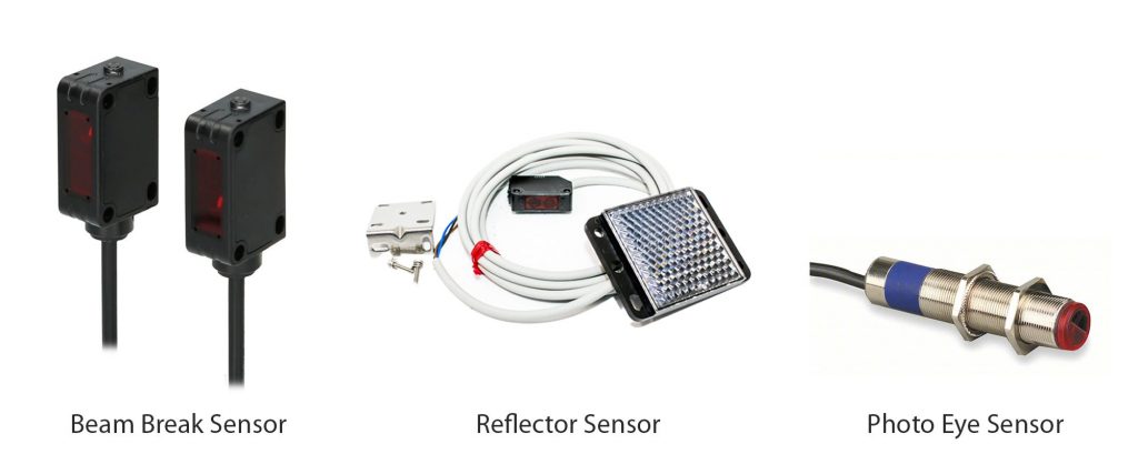
When using a digital input sensor the the Rising edge of the pulse is used for the cycle count.
Accelerometer Sensor
The Cycle and Uptime Tracker is an innovative device engineered to monitor and record the number of cycles and total uptime of machinery or equipment in industrial environments. Leveraging advanced acceleration sensing technology, users can set customizable acceleration thresholds to precisely detect cycle initiations. This allows for accurate tracking of machine activity while minimizing false readings. The device captures and stores data, providing insights into equipment usage patterns and overall uptime. With its user-friendly interface and customizable settings, operators can easily configure acceleration thresholds to suit specific machinery requirements. Ideal for diverse industrial applications, the Cycle and Uptime Tracker enhances maintenance planning, optimizes production scheduling, and improves operational efficiency.
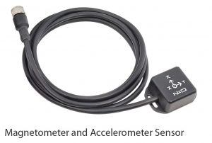
Magnetometer Sensor
Magnetic Field-Based Machine On/Off Detection System is meticulously engineered to precisely discern the operational status of machinery that emits magnetic fields during operation. Employing cutting-edge magnetic field sensors, this system offers unparalleled accuracy in identifying whether the machine is active or inactive. With its robust design and reliable performance, there’s no need for user adjustments, ensuring hassle-free operation. Real-time monitoring capabilities enable proactive maintenance planning and energy conservation, enhancing operational efficiency. Seamlessly integrating into various industrial setups, this system represents a pinnacle of reliability and professionalism in machine monitoring solutions.
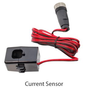
Current Sensor
Industrial Machine Uptime and Cycle Counter, a cutting-edge solution that accurately measures total machine uptime and cycle counts using advanced current sensor technology. With real-time monitoring and seamless integration, our device enables proactive maintenance planning, enhances operational efficiency, and provides valuable insights for informed decision-making. Upgrade your industrial operations with precise tracking and analysis capabilities for optimized performance and cost savings.
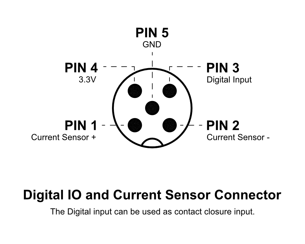
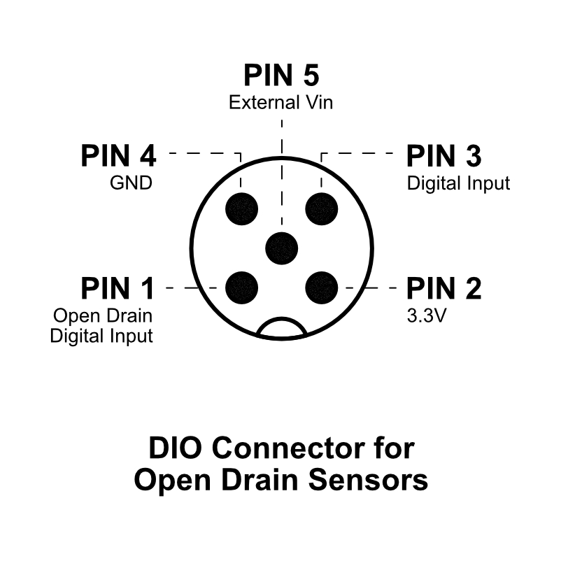
Pin Definition

Getting started
The process is straight forward however you need two components:
- A device to ingest the data, either a DigiMesh modem or a Gateway, we recommend using the IIoT Edge Gateway as it comes with Node-Red pre-installed.
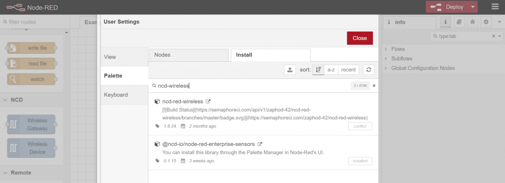
- A working Node-Red instance to process the data (unless using the IIoT Edge Gateway). You can easily install the NCD library by looking it up in your Node-Red Pallet Manager. Search for “ncd-wireless”. Alternately you can manually install it via command line from the following Git repo: https://github.com/ncd-io/ncd-red-wireless
For a quick refresher on how to set up your Gateway for the first time, please head to our article on the topic. Once you have it connected to your network and have it set up to connect to the Internet, you can connect directly to its Node-Red instance via the following address:
XX.XX.XX.XX:1880
Where xx.xx.xx.xx stands for the local IP address of the Gateway (for example the one assigned to it via your router, or manually set via its settings) and the port used is 1880 (this is the default for the Node-RED instance running on the NCD Edge gateway).
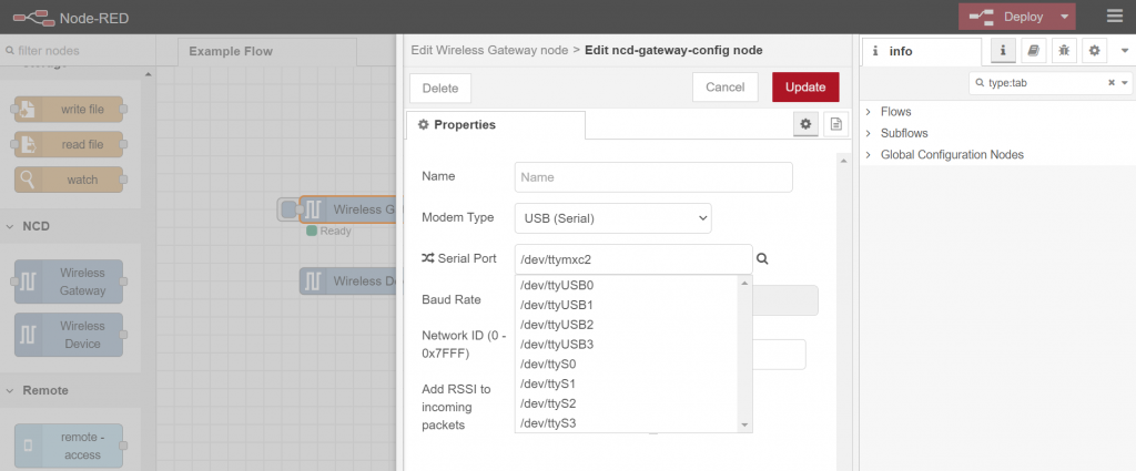
You need to create the flow from the image below. There are two main components: Wireless Gateway (whether this is the Modem or the IIoT Edge) and Wireless Device (this represent the sensor).
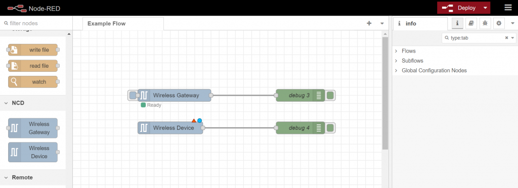
Depending on the particular devices the following settings will differ (the particular example is using the IIoT Edge and a Vibration Sensor). You need to configure the Gateway and the Device to utilize the right interfaces.
If you are unsure on how to c
Let us start with the Gateway.
Double click on the block to see the Properties, enter a name and press on the Pen icon next to the Serial text box to add a new Serial Device.
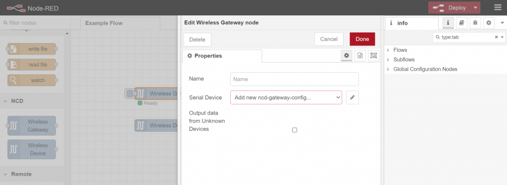
Give it a name select the appropriate port (depending on what device you are using, you nee to check this for your system). If you press on the magnifying glass a list of ports will be displayed. Select the one right for your use case (the IIoT Edge uses /dev/ttymx2). Select the Baud rate and press the Red button to save it. Press on the Red button again to finalize setting up the Gateway.
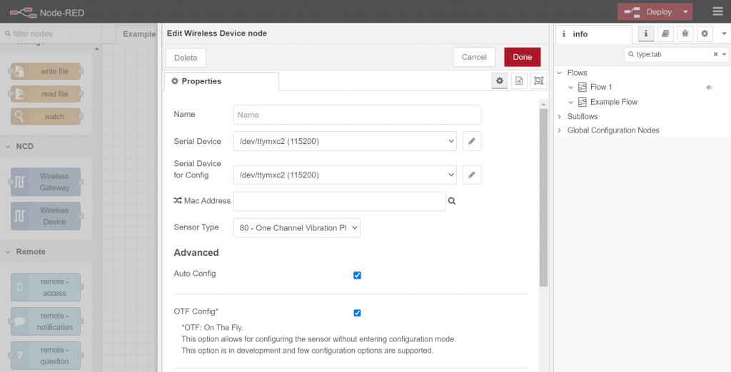
Setting up the Device is similar.
Open up the properties and fill in the name. For the Serial Device and the Serial Device for Configuration select the port you just created for the Gateway from the drop down menu. This way data from the sensor will be relayed to the Gateway. Leave the MAC address empty for now (this will ingest data indiscriminately, you can filter it later, the MCA will be displayed in the packets themselves). Select the Sensor Type (in this example 80 – One Channel Vibration Plus. This will allow you to set up Advanced properties.
Check the box for Auto Config and OTF Config. This will allow the device to work in OTF mode where configuration is pushed On The Fly and you can change settings via the Advance parameters further down if need be (the sensor needs to be reset for this).
Close up the window and you are done. Deploy our flow and you should see data being ingested.
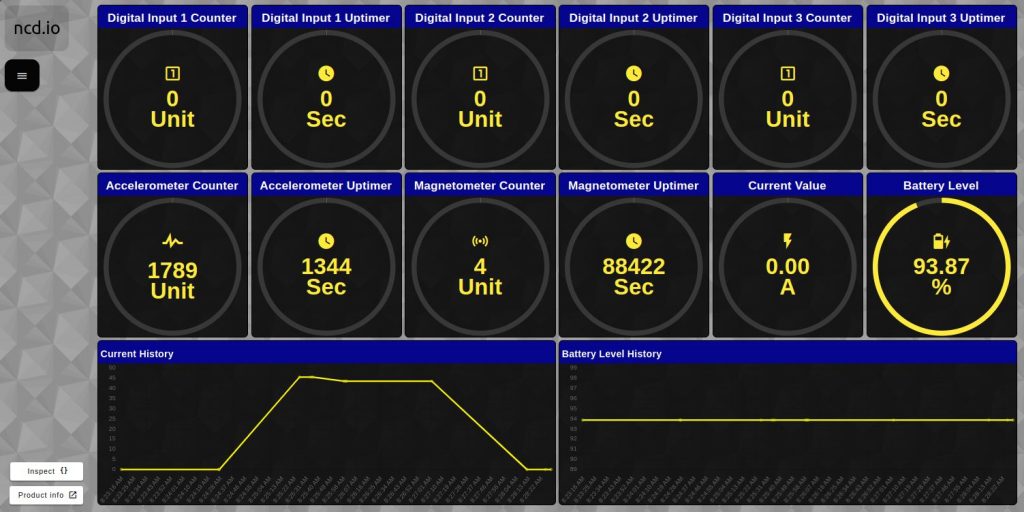
Node-RED Dashboard
NCD offers an easy to use solution that you can run locally to display your data. Using the Machine Uptime sensor together with either the Edge Gateway or Edge Lite Gateway if the quickest way to connecting your sensor to a Node-RED instance (they come with a built-in one that is pre-configured).
We have a dedicated tutorial how to utilize our libraries and the flows we have created so you can create a dashboard customized for this particular sensor, follow the link to get started.
Advanced Configuration
Once the Machine Uptime sensor has been powered on and its initial configuration performed you can choose to configure advanced settings/features. This customization is there to allows the user to better tailor the functionality for a specific application/use-case.
In order to better understand how to manipulate the device settings we need to explain its 2 operational modes in detail. These modes are:
Run Mode
This is the default mode and the device enters into it when it is Powered-up/Reset unless a button is pressed. In this mode the device sends regular uplinks and acts in accordance with the configuration parameters unless changed.
Configuration Mode
This is a temporary mode that is not intended for long-term operation. The device goes out of it an back to Run Mode after every Reset/Power cycle. It is intended to adjust the sensor parameter values. You can enter in this mode by pressing the CFG button while resetting the device (refer to the graph below for the precise timing of the CFG button press).
Note: The device checks every hour for configuration changes and automatically updates its settings, you need not physically interact with it to update it!
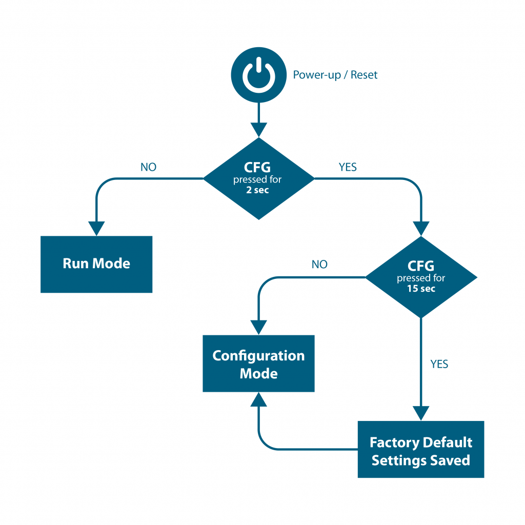
CFG Button timings
- <2 second – device starts normally in RUN Mode
- 2 to 15 seconds – device goes into Configuration Mode
- >15 seconds – the device reverts back to the Factory Default Settings, which is followed by a Configuration Mode Frame
Note: Pressing the button while the Machine Uptime device is running does no change modes, it needs to be reset (either via the Reset Button or Power Cycling). In order for the new settings to apply the devices needs to be Reset.
Factory Default/Reset
In case you have are in need to revert to the default settings (>15 seconds of CFG Button press when Reset), you can utilize the following table to look up their values. This will be implemented once the device has been reset (post Configuration mode).
Note: Post factory reset the sensor will be sending frames with the default interval of 600 seconds (every 10 minutes).
| Parameters | Value set |
|---|---|
| Node ID | 0 |
| Delay | 600 (DEC) seconds |
| Destination Address | 00 00 FF FF (HEX) |
| PAN ID | 7F FF (HEX) |
| Key | {85,170,85,170,85,170,85,170,85,170,85,170,85,170,85,170} (DEC) |
| Encryption | Enabled |
| Change Detection | Enabled |
| Change Detection Percentage | 10% |
| Change Detection Time | 7 seconds |
Frame Communication at Power Up
When the Machine Uptime device powers up, depending on the mode it is going to work in, it will have a different Power Up Frame
Figure 3 provides an outline of the frame structure at Power Up, where the bytes highlighted in Red denote which mode the device has started in (Run, Configuration or Factory Default). You can look up the corresponding codes in Table 2.
If we further examine the Payload, we can use the Node ID and Sensor Type fields to determine the exact sensor that is sending the data.
A shown in the second column in Table 2, the sensor configures its PAN ID automatically depending upon the mode it is working in. During factory reset it sets the PAN ID to the value given in table therefore the factory reset frame will only be received if your Modem/Gateway PAN ID matches this ID. All 3 types of frames are shown in Figure 3, Figure 4 and Figure 5.
Note: Right after factory reset the sensor enters configuration mode therefore its PAN ID is changed again and a new frame is generated.
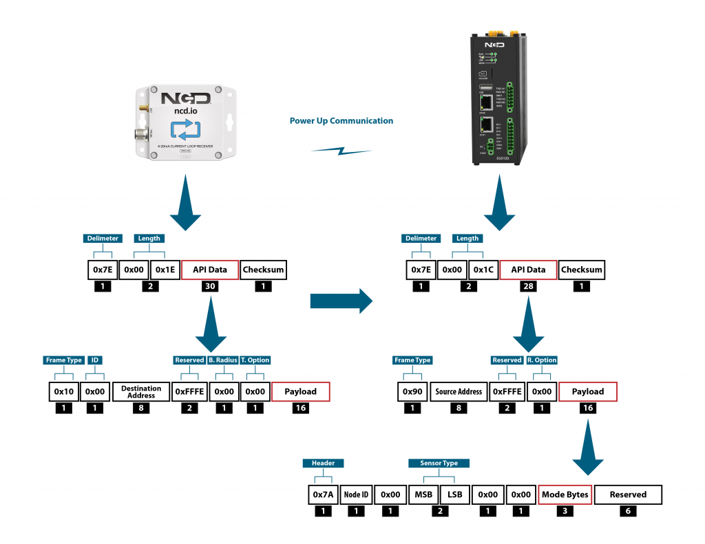
| Mode Type | PAN ID set by Sensor (ASCII) | Frame field | Offset (Payload section) | Value |
|---|---|---|---|---|
| Run | ID save by user / Default | Mode bytes | 7 | 0x52 |
| 8 | 0x55 | |||
| 9 | 0x4E | |||
| Configuration | 7BCD | Mode bytes | 7 | 0x50 |
| 8 | 0x47 | |||
| 9 | 0x4D | |||
| Factory Reset | 7FFF | Mode bytes | 7 | 0x50 |
| 8 | 0x55 | |||
| 9 | 0x4D |
Let us look at the 3 possible power up frames to give an example:
Run Mode Power Up Frame
| Field | Number of bytes | Description |
|---|---|---|
| 7E 00 1C 90 00 13 A1 00 41 58 1C CB FF FE 00 7A 01 00 00 01 00 00 52 55 4E 00 00 00 00 00 00 0B | Example frame | |
| 0x7E | 1 | Delimiter |
| 0x001C | 2 | Length |
| 0x90 | 1 | Frame Type (Power Up) |
| 0x0013A1004158C1CB | 8 | Source Address |
| 0xFFFE | 2 | Reserved |
| 0x00 | 1 | R. Option |
| 0x7A | 1 | Header with Power Up value |
| 0x01 | 1 | Node ID |
| 0x00 | 1 | Separator |
| 0x0001 | 2 | Sensor Type |
| 0x0000 | 2 | Separator |
| 0x52554E | 3 | Mode Byte for Run Mode |
| 0x000000000000 | 6 | Reserved |
| 0x0B | 1 | Checksum |
Configuration Mode Power Up Frames
| Field | Number of bytes | Description |
|---|---|---|
| 7E 00 1C 90 00 13 A1 00 41 58 1C CB FF FE 00 7A 01 00 00 01 00 00 50 47 4D 00 00 00 00 00 00 1C | Example frame | |
| 0x7E | 1 | Delimiter |
| 0x001C | 2 | Length |
| 0x90 | 1 | Frame Type (Power Up) |
| 0x0013A1004158C1CB | 8 | Source Address |
| 0xFFFE | 2 | Reserved |
| 0x00 | 1 | R. Option |
| 0x7A | 1 | Header with Power Up value |
| 0x01 | 1 | Node ID |
| 0x00 | 1 | Separator |
| 0x0001 | 2 | Sensor Type |
| 0x0000 | 2 | Separator |
| 0x50474D | 3 | Mode Byte for Configuration Mode |
| 0x000000000000 | 6 | Reserved |
| 0x0E | 1 | Checksum |
Factory Reset Mode Power Up Frames
| Field | Number of bytes | Description |
|---|---|---|
| 7E 00 1C 90 00 13 A1 00 41 58 1C CB FF FE 00 7A 01 00 00 01 00 00 50 47 4D 00 00 00 00 00 00 1C | Example frame | |
| 0x7E | 1 | Delimiter |
| 0x001C | 2 | Length |
| 0x90 | 1 | Frame Type (Power Up) |
| 0x0013A1004158C1CB | 8 | Source Address |
| 0xFFFE | 2 | Reserved |
| 0x00 | 1 | R. Option |
| 0x7A | 1 | Header with Power Up value |
| 0x01 | 1 | Node ID |
| 0x00 | 1 | Separator |
| 0x0001 | 2 | Sensor Type |
| 0x0000 | 2 | Separator |
| 0x50474D | 3 | Mode Byte for Configuration Mode |
| 0x000000000000 | 6 | Reserved |
| 0x0E | 1 | Checksum |
Run Mode
Run mode is the default mode of operation of this sensor. In this mode, the Machine Uptime sensor sends periodic packets with the sensor measurement data. During the time it is not sending it enters deep-sleep to conserve power. The sensor’s X-bee module operates in API mode and sends packets to the saved destination address on the network specified by the saved PAN ID. Figure 4 illustrates the API transmission/reception procedure.
Note: The communication works in confirmed mode, meaning that acknowledgements are received for each transmitted packet. In case no acknowledgement is received for a packet, the device retransmits the packet up to 3 time in an attempt to successfully send it over. This is part of the X-bee API functionality and is built-in (does not need to be user coded).
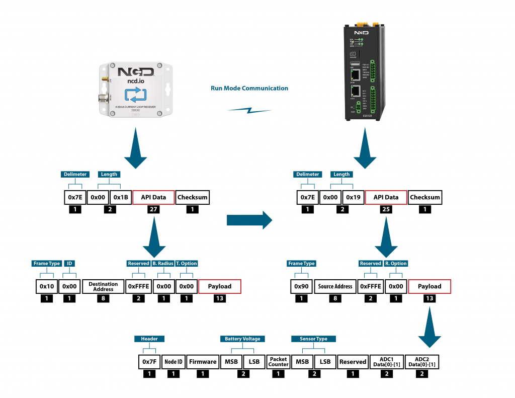
The detail of Payload section of packet is shown in Table 3 below:
| Frame Field | Offset (Payload section) | Fixed Value (if any) | Length | Description |
|---|---|---|---|---|
| Header | 0 | 0x7F | 1 | Header to differentiate various types of packets |
| Node ID | 1 | 0x00 | 1 | Node ID to differentiate up to 256 nodes in a network. User configurable values |
| Firmware | 2 | 0x01 | 1 | Used to determine firmware version programmed in the device |
| Battery Voltage | MSB 3 | 0x03 | 2 | Battery Voltage = 0.00322*(03*FF+FE) |
| LSB 4 | 0xFE | Battery Voltage = ((Battery Voltage MSB x 256) + Battery Voltage LSB) x 0.00322 V | ||
| Packet Counter | 5 | - | 1 | It is an 8-bit counter that increments with each packet transmission. It can be used to detect missing packets |
| Sensor Type | MSB 6 | 0x00 | 2 | Two bytes to determine sensor type. It can be used in conjunction with Node ID to create sensor networks of up to 256 nodes for a single type of sensor and multiple such networks can coexist and can be differentiated in processing software on PC end. |
| LSB 7 | 0x6C | Sensor Type 108 | ||
| Error/Reserved byte | 8 | 0x00 | 1 | Reserved |
| Digital Input 1 Counter | 9/ Data[0] | - | 4 | Counter 1 = Data[0] << 24 | Data[1] << 16 | << Data[2] << 8 | Data[3] |
| 10/ Data[1] | ||||
| 11/ Data[2] | ||||
| 12/ Data[3] | ||||
| Digital Input 1 Uptime | 13/ Data[0] | - | 4 | Uptime 1 = Data[0] << 24 | Data[1] << 16 | << Data[2] << 8 | Data[3] |
| 14/ Data[1] | ||||
| 15/ Data[2] | ||||
| 16/ Data[3] | ||||
| CT Input Counter | 17/ Data[0] | - | 4 | CT Input Counter = Data[0] << 24 | Data[1] << 16 | << Data[2] << 8 | Data[3] |
| 18/ Data[1] | ||||
| 19/ Data[2] | ||||
| 20/ Data[3] | ||||
| CT Input Uptime | 21/ Data[0] | - | 4 | CT Input Uptime = Data[0] << 24 | Data[1] << 16 | << Data[2] << 8 | Data[3] |
| 22/ Data[1] | ||||
| 23/ Data[2] | ||||
| 24/ Data[3] | ||||
| Opto Input Counter | 25/ Data[0] | - | 4 | Opto Input Counter = Data[0] << 24 | Data[1] << 16 | << Data[2] << 8 | Data[3] |
| 26/ Data[1] | ||||
| 27/ Data[2] | ||||
| 28/ Data[3] | ||||
| Opto Input Uptime | 29/ Data[0] | - | 4 | Opto Input Uptime = Data[0] << 24 | Data[1] << 16 | << Data[2] << 8 | Data[3] |
| 30/ Data[1] | ||||
| 31/ Data[2] | ||||
| 32/ Data[3] | ||||
| Accelerometer Input Counter | 33/ Data[0] | - | 4 | Accelerometer Input Counter = Data[0] << 24 | Data[1] << 16 | << Data[2] << 8 | Data[3] |
| 34/ Data[1] | ||||
| 35/ Data[2] | ||||
| 36/ Data[3] | ||||
| Accelerometer Input Uptime | 37/ Data[0] | - | 4 | Accelerometer Input Uptime = Data[0] << 24 | Data[1] << 16 | << Data[2] << 8 | Data[3] |
| 38/ Data[1] | ||||
| 39/ Data[2] | ||||
| 40/ Data[3] | ||||
| Magnetometer Input Counter | 33/ Data[0] | - | 4 | Magnetometer Input Counter = Data[0] << 24 | Data[1] << 16 | << Data[2] << 8 | Data[3] |
| 34/ Data[1] | ||||
| 35/ Data[2] | ||||
| 36/ Data[3] | ||||
| Magnetometer Input Uptime | 37/ Data[0] | - | 4 | Magnetometer Input Uptime = Data[0] << 24 | Data[1] << 16 | << Data[2] << 8 | Data[3] |
| 38/ Data[1] | ||||
| 39/ Data[2] | ||||
| 40/ Data[3] | ||||
| Input Logic State | 41/ Data[0] | - | 1 | Bit 1: Logic Status Digital Input Bit 2: Logic Status CT current Input Bit 3: Logic Status Opto Input Bit 4: Logic Status Accelerometer Input Bit 5: Logic Status Magnetometer Input |
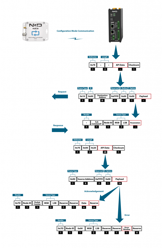
Configuration Mode
Configuration Mode (enter via CFG key press) is intended to setup the device over the wireless link, you can change parameter values that are subject to change via downlink commands.
In configuration mode, the device sets its X-bee pan id to 7BCD (Table 2). Also, the destination address used by the sensor is extracted from the incoming packet (source address). This ensures that once you put a device in configuration mode you just need to change the PAN ID you are sending to in your Modem/Gateway to match with the sensor and start configuring your device.
A standard configuration packet and its fields are explained in Figure 5. Its possible responses are also shown. The complete set of commands supported by this sensor are shown in Appendix A, these can be used in the Parameters field of the Payload section. The sensor responds to these commands with an acknowledgement if the process completed successfully or with an error if it failed to setup a parameter. The respective Data and Reserve section length and values are shown in Table 6 for the case of acknowledgement. In the case of error, the reserved section will be fixed and not used, while the Error number byte will determine the type of error returned. These errors are mentioned in Table 7.
Note: Sensor commands have variable length frames whereas responses received from sensor are fixed length. The 2 scenarios are also shown, where a command can result in an acknowledgement reception or an error reception.
Example Configuration Commands
The following set of commands are an example on how to change some of the parameters that affect the operation of the Machine Uptime device (these are parameters that are general in nature, more on a network protocol/device level than device specific). The relate to settings that are independent of the type of probe used. You can find them in Appendix A as well.
Device/Application Specific command you can find in Appendix C.
Read Sleep Duration
This command may be used to read the sensor sleep duration. The sleep duration determines how frequently the sensor wakes up and send sensor data. The interval is set in seconds. Short intervals will drain the battery faster while longer intervals will provide a very long battery life.
Read Sleep Duration Command
7E 00 13 10 00 00 00 00 00 00 00 FF FF FF FE 00 00 F7 15 00 00 00 E8
In the above command the remote device address is set as broadcast. The address is:
00 00 00 00 00 00 FF FF
When sending this command to a particular sensor, replace the MAC address of the sensor. Again, the sensor MUST be in configuration mode.
The Wireless Sensor will respond with the stored delay value:
7E 00 1C 90 00 13 A2 00 41 91 1B 83 FF FE C1 7C 00 02 00 0E 00 00 00 02 58 00 00 00 00 00 00 A6
From the above command, the following data may be extracted:
A. Sensor MAC address
00 13 A2 00 41 91 1B 83
B. Sensor Over-all Payload
7C 00 02 00 0E 00 00 00 02 58 00 00 00 00 00 00
C. Delay Value
0x00 0x02 0x58 (data bytes 23, 24, and 25)
Delay in Seconds = (0x00 x 65536) + (0x02 x 256) + 0x58 = 600 Seconds = 10 Minutes
Set Sensor Node ID and Sleep Duration
This Command may be used to set the sensor node and sleep duration, note that both values are stored together using the same command. The Node ID is a user-defined value from 00 to FF that may be used to help easily identify a sensor. The Sleep Duration indicates the amount of time (in seconds) the sensor will sleep before waking up, taking a sample, sending a transmission, and going back to sleep.
Set Node ID and Sleep Duration Command Example:
7E 00 17 10 00 00 00 00 00 00 00 FF FF FF FE 00 00 F7 02 00 00 00 01 00 01 2C CD
In the above command, the remote device address is set to broadcast mode. The broadcast address is 00 00 00 00 00 00 FF FF, which will target all sensors in configuration mode. Change the broadcast address to the MAC address of a individual sensor to target a particular sensor with this command (this is usually not required). The Command Contains a Sensor payload which contains a Sensor Node ID and Delay value.
Payload
F7 02 00 00 00 01 00 01 2C
Note that F7 is the command header byte and 02 is the sub command for storing the Node ID and Sleep Duration.
A. Node ID
0x01 (Byte 23)
B. New Delay Value
00 01 2C (data bytes 24, 25, and 26)
Delay in seconds = (0x00 x 65536) + (0x01 x 256) + 0x2C = 300 Seconds = 5 Minutes
In the Above command we set the new node to 1 and sleep duration value to 300 seconds (5 Minutes).
Once the sensor receives this command, it will send a response back. This response will indicate success or failure of the command.
In his case, the response will look something like this:
7E 00 1C 90 00 13 A2 00 41 91 1B 83 FF FE C1 7C 01 05 00 0E 00 00 FF 00 00 00 00 00 00 00 00 FD
Read Sensor Network ID
The Network ID is also known as PAN ID (Personal Area Network ID). This feature may be used to build a private Wireless Sensor Network. All sensors with the same Network ID will be able to talk to modems and gateway with the same Network ID. This is useful when deploying hundreds of sensors in one area or applications which require division of sensors, modems, and gateways into different zones with independent monitoring of each zone. Each sensor, gateway, and modem in a specific zone should share identical Network IDs, allowing the separation of sensors into smaller, more manageable groups.
Large factory floors or high-rise building may consist of several groups of sensors working under different Network IDs that help characterize the different areas of the installation. Network IDs make it easy to group sensors, modems, and gateways. When broadcasting data using separate Network IDs, multiple modems and gateways may be used in each zone, allowing sensor data to be collected by several different computers or servers. This kind of redundancy is essential in large installations.
Read Sensor Network ID Command
7E 00 13 10 00 00 00 00 00 00 00 FF FF FF FE 00 00 F7 19 00 00 00 E4
Sensor will respond with the Network ID
7E 00 1C 90 00 13 A2 00 41 91 1B 83 FF FE C1 7C 00 05 00 0E 00 00 7F FF 00 00 00 00 00 00 00 7F
From the above response, following data may be extracted:
A. Sensor MAC Address
00 13 A2 00 41 91 1B 83
B. Complete Sensor Payload
7C 00 05 00 0E 00 00 7F FF 00 00 00 00 00 00 00
C. Network ID
0x07FF (data bytes 23 and 24)
Set Wireless Sensor Network ID
This command may be used to set the sensor Network ID. Please note, Network ID 0x7BCD is reserved for configuration and should NEVER be used as a network ID for general use. Please note the Modem/Gateway must also use a matching Network ID to communicate with the sensor.
Set Wireless Sensor Network ID Command:
7E 00 15 10 00 00 00 00 00 00 00 FF FF FF FE 00 00 F7 05 00 00 00 7C DE 9E
Above Command Contains the following payload:
F7 05 00 00 00 7C DE
Note that F7 is the command header byte and 05 is the sub command for setting the Sensor Network ID.
In the Above command, a new network ID of 0x7CDE is configured.
Once the sensor receives this command, it will send a response back. This response will contain information regarding command success or failure.
In his case the response was successful, responding with the following frame:
7E 00 1C 90 00 13 A2 00 41 91 1B 83 FF FE C1 7C 00 09 00 0E 00 00 FF 00 00 00 00 00 00 00 00 FA
Read Sensor Destination Address
This Command may be used to read the sensor destination address. When the Sensor is in broadcast mode, the destination address will show up as:
0x0000FFFF
This Command may be used to read the sensor destination address.
Read Sensor destination address Command:
7E 00 13 10 00 00 00 00 00 00 00 FF FF FF FE 00 00 F7 18 00 00 00 E5
Sensor will respond with the Stored destination address:
7E 00 1C 90 00 13 A2 00 41 91 1B 83 FF FE C1 7C 00 13 00 0E 00 00 00 00 FF FF 00 00 00 00 00 F1
From the above command, the following data may be extracted:
A. Complete Sensor Payload
7C 00 13 00 0E 00 00 00 00 FF FF 00 00 00 00 00
B. Sensor MAC address
00 13 A2 00 41 91 1B 83
C. Destination Address
0000FFFF (data bytes 23, 24, 25, and 26)
The sensor response 0000FFFF indicates that the sensor is in broadcast mode. Any other value will indicate the sensor is directing its data to a specific address (a specific modem or gateway). We DO NOT ADVISE sending sensor data to a specific address, we advise broadcasting data using different Network IDs (PAN IDs) to put data into clustered zones. Should a specific gateway or modem fail while in service, it will be much easier to deploy a new gateway or setup redundant gateways and modems. Otherwise, reconfiguration of each sensor for a new gateway or modem will be required.
Set Sensor Destination Address
Every sensor is designed to send sensor data either in broadcast mode or to a particular destination address (modem or gateway). By default, NCD sensors broadcast data to all available modems and gateways. Data may be restricted to a single destination address (modem or gateway), though this configuration does not provide any form of redundancy in the event of a Modem or Gateway outage. For this reason, we strongly advise against using this command. Please consider setting the Network ID (PAN ID) to Setup Zones which will allow for redundancy in the event of a service outage. The following command is provided for reference ONLY and should be used with caution as a modem or gateway failure will necessitate reconfiguration of each sensor (which would not be required if the Pan ID/Network ID were used).
What is a Destination Address? Every sensor, gateway, and modem have a unique MAC address which cannot be changed. This MAC address is also known as the destination address (printed on the side of the enclosure). By default, all sensors send data in broadcast mode. This allows all the gateways and modems in the area to receive sensors data provided they are all on the same PAN ID (Network ID) and use the same encryption key.
When a specific destination address is stored in the sensor, the sensor will send data to that specific destination address only. The sensor CANNOT communicate with any other modem or gateway in the area. The following command may be used to specify a specific destination address (modem or gateway) for all sensor data:
Set Destination address Command
This command we will send only the lower 4 bytes of the destination address (the upper 4 bytes do not change).
7E 00 17 10 00 00 00 00 00 00 00 FF FF FF FE 00 00 F7 03 00 00 00 12 34 56 78 E6
The above Command Contains the payload, including a New Sensor destination address:
Complete Payload
F7 03 00 00 00 12 34 56 78
F7 is the command header byte and 03 is the sub command for setting a specific destination address. In this example, the new Destination Address is 12345678.
Once sensor receives this command it will send a response back. This response will indicate the command success or failure.
In his example, the response will look something like this (if successful):
7E 00 1C 90 00 13 A2 00 41 91 1B 83 FF FE C1 7C 00 0E 00 0E 00 00 FF 00 00 00 00 00 00 00 00 F5
Set Sensor Destination to Broadcast
This Command may be used to set the sensor destination address to broadcast mode, which is the default operation of NCD long range wireless sensors. After setting to broadcast mode, all modems and gateways with the same PAN ID and Encryption key will receive the same sensor data. This is the preferred configuration for all NCD sensors. Segmenting sensors into groups requires a unique PAN ID (also known as Network ID) for each group. All sensors, modems, and gateways must share the same PAN ID for each group.
Set Sensor Destination address to broadcast:
7E 00 13 10 00 00 00 00 00 00 00 FF FF FF FE 00 00 F7 01 00 00 00 FC
Complete Payload
F7 01 00 00 00
F7 is the command header byte and 01 is the sub-command for setting the Destination Address to Broadcast Mode.
Read Wireless Sensor Transmission Power Level
This Command may be used to read the wireless radio transmission power. This value will indicate how much RF power the radio is emitting. The higher the value, the higher the radiated wireless power, resulting in a longer range and decreased battery life (please note that all battery ratings are shown at maximum wireless transmission power). Lower values are desirable in application that may benefit from greatly improve battery life, especially when high power data transmissions are not required.
Read Sensor Power Command:
7E 00 13 10 00 00 00 00 00 00 00 FF FF FF FE 00 00 F7 16 00 00 00 E7
Sensor will respond with the Power Level value:
7E 00 1C 90 00 13 A2 00 41 91 1B 83 FF FE C1 7C 00 09 00 0E 00 00 04 00 00 00 00 00 00 00 00 F5
From the above command, the following data may be extracted:
A. Sensor MAC Address
00 13 A2 00 41 91 1B 83
B. Sensor Payload
7C 00 09 00 0E 00 00 04 00 00 00 00 00 00 00 00
C. Power Level
0x04 (data byte 23)
The sensor will respond with a value from 0x00 to 0x04. The default value is 0x04, allowing for the greatest possible transmission range and the shortest battery life.
Read Wireless Sensor Retries
The following command may be used to read the number of retires. The number of retries is one of the most useful settings for NCD wireless sensors.
Lets say the number of retires is set to 5. In a normal case, the sensor will wake up, gather data, send data to the modem, and go back to sleep. But due to some environmental issues (lets say a few trucks were driving by and they came in between the sensor and the modem) the modem didn’t receive the data. In that case, the sensor will try 4 more times to send the data. If the modem still doesn’t get the data after all 5 tries, the sensor will quite trying and will go back to sleep. The Machine Uptime sensor will wake up after the predefined sleep time and will try again.
The highest number of retries allowed is 10.
Read The number of Sensor Retries:
7E 00 13 10 00 00 00 00 00 00 00 FF FF FF FE 00 00 F7 17 00 00 00 E6
Sensor will respond with the Retries value:
7E 00 1C 90 00 13 A2 00 41 91 1B 83 FF FE C1 7C 00 1B 00 0E 00 00 0A 00 00 00 00 00 00 00 00 DD
From the above command, the following data may be extracted:
A. Sensor MAC Address
00 13 A2 00 41 91 1B 83
B. Complete Sensor Payload
7C 00 1B 00 0E 00 00 0A 00 00 00 00 00 00 00 00
C. Retries Number
0x0A (data byte 23)
Set Wireless Sensor number of Retries
This Command may be used to change the number of retries. The highest number of retries allowed is 10:
7E 00 14 10 00 00 00 00 00 00 00 FF FF FF FE 00 00 F7 06 00 00 00 05 F2
The above Command Contains a Sensor payload which contains a new number of retries value:
Complete Payload
F7 06 00 00 00 05
F7 is the command header byte and 06 is the sub command for setting the Retries value.
In the Above command we set the retries value to 5 (byte 23).
Once the sensor receives this command, it will send a response back. This response will contain the info regarding command success or failure.
In his case the response was successful:
7E 00 1C 90 00 13 A2 00 41 91 1B 83 FF FE C1 7C 00 1D 00 0E 00 00 FF 00 00 00 00 00 00 00 00 E6
Set Wireless Sensor Encryption Key
This Command may be used to set the encryption key.
All ncd.io wireless sensors comes with 128bit AES encryption. The default encryption key secures a wireless sensor network of sensors, modems, and gateways. Users have the option to change the default encryption key. Please note this is a Write ONLY operation, it is not possible to read the encryption key from Sensors, Modems, or Gateways. Be Sure to keep records accordingly.
Once the sensor encryption key is set in the sensor, be sure to set the same key in all modems and gateways. If the modem or gateway doesn’t have the same key and PAN id as the sensor, there will be no way for sensors to communicate with modems or gateways. In this event, only a factory reset may be used to recover communications.
The following Command may be used to change the encryption key:
7E 00 24 10 00 00 00 00 00 00 00 FF FF FF FE 00 00 F2 03 00 00 00 00 55 AA 55 AA 55 AA 55 AA 55 AA 55 AA 55 AA 55 AA 07
Complete Payload
F2 03 00 00 00 00 55 AA 55 AA 55 AA 55 AA 55 AA 55 AA 55 AA 55 AA
F2 is the command header byte and 03 is the sub command for setting the ENY Key value.
Note — There is an Extra 0x00 Right before the ENY key value. Its a reserve byte and it should be there all the time.
In the Above command, the default ENY Key value is programmed into the NCD sensor.
55 AA 55 AA 55 AA 55 AA 55 AA 55 AA 55 AA 55 AA
Once the sensor receives this command, it will change the Key immediately.
In the event a key value is lost, factory reset the device. The default key value will always be used after factory reset:
55 AA 55 AA 55 AA 55 AA 55 AA 55 AA 55 AA 55 AA
Troubleshooting
Here are some common issue one might encounter when first setting up the sensor or later on when advance configuration is performed:
1. No or low range/coverage. Data is not received by the Modem/Gateway. Make sure you have properly installed the antenna and have as little obstructions/metal surrounding the sensor.
2. Measurement data missing or values are inconsistent. This might be due to not installing/tightening the probe correctly. Make sure you screw it in all the way and that you position it appropriately where you want to perform the measurements,
3. In case data is not being received (was previously received) there might be a power issue. Check the batteries and or the status of the internal LEDs. You can also observe the battery voltage value in the Run Mode packets you last received to know if the batteries have diminished too much for the sensor to operate.
4. If there are connectivity issue where data is being received intermittently or packets are being lost/need retransmission, make sure that you are in a RF heavy noise environment and/or the sensor is not separated too far away from the nearest node. You might need to install more nodes to bust coverage. Check if the Modem/Gateway is powered properly and operation and its antenna has been installed properly.
5. In case you still can’t solve your issue head to our Community forum to get real time help from the NCD community of experts: https://community.ncd.io/
Appendix A - Configuration Commands
Node-RED can be used to configure the device (check the Quick Start section), however you can use any tool as long as you adhere to the proper command structure described in this chapter.
Refer to the table below for a list of commands, their codes and an explanation of what parameter they affect.
| No. | Command | Header | Sub Command | Parameter Field | Default Value | Description |
|---|---|---|---|---|---|---|
| 1 | Set Broadcast Transmission | 0XF7 | 0x01 | - | 0000FFFF | This will set the address to Broadcast mode. All the receiver with same ENY key and PAN ID will get the data packets |
| 2 | Set ID and Sleep Interval | 0XF7 | 0x02 | NODE ID, D0 MSB,D1, D2 LSB | 0x00,0x00,0x02,0x58 | Sets the Device node ID and Data Transmission Interval. The node id value can go from 0-255 and The Data transmission value can go from 3-0xFFFFFF Seconds |
| 3 | Set Destination Address | 0XF7 | 0x03 | A0 MSB, A1, A2, A3 | 00,00,FF,FF | Sets the Destination Address of the sensor. The sensor will send Run mode Data packets to this Address |
| 4 | Set Power | 0XF7 | 0x04 | Power ( range 1-4) | 0x04 | Sets the RF power of the Sensor Radio |
| 5 | Set PAN ID aka Network ID | 0XF7 | 0x05 | ID0 MSB, ID1 LSB | 0x7FFF | Sets the PAN ID aka Network ID in the sensor. Only sensors, Gateway, and Modes with Same ID can communicate with each other |
| 6 | Set Retries | 0XF7 | 0x06 | Retries | 0x0A | Sets the number of Retries after unsuccessful transmission for the Sensor Radio |
| 7 | Read Sleep Interval | 0XF7 | 0x15 | - | 0x00,0x02,0x58 | Reads the stored Sleep Interval value from the sensor |
| 8 | Read Power | 0XF7 | 0x16 | - | 0x04 | Reads the stored RF Power value from the sensor |
| 9 | Read Retries | 0XF7 | 0x17 | - | 0x0A | Reads the stored Retries value from the sensor |
| 10 | Read Destination Address | 0XF7 | 0x18 | - | 00,00,FF,FF | Reads the stored Destination value from the sensor |
| 11 | Read PAN ID aka Network ID | 0XF7 | 0x19 | - | 0x7FFF | Reads the PAN ID aka Network ID |
| 12 | Enable Encryption | 0XF2 | 0x01 | - | 0x01 | Enables the Encryption of the Frame Transmitted from the Sensor |
| 13 | Disable Encryption | 0XF2 | 0x02 | - | - | Disables the Encryption of the Frame Transmitted from the Sensor |
| 14 | Set Encryption Key | 0XF2 | 0x03 | 00,K0 MSB, K1,K2,K3,K4,K5,K6,K7,K8,K9,K10,K11,K12,K13,K14,K15 | 55AA55AA55AA55AA55AA55AA55AA55AA | Sets the 128 bit AES Encryption Key |
| 15 | Set Change Detection Parameters | 0XF7 | 0x07 | E, PR, T0 MSB, T1, T2 LSB | Enable or disable the percentage change detection. E=1 (Enable), E=0 (Disable) PR is the percentage change detection at which the sensor will send a packet. The sensor sends a packet when two consecutive readings differ by PR percent T0, T1, T2 - This is the detection time after which the sensor periodically checks for PR percent change in sensor data from last sample |
|
| 16 | Read Change Detection Parameters | 0XF7 | 0x1A | - | Refer to Command 15 above for the explanation. |
Appendix B - Command Acknowledgement Data
Each command (Appendix A) has its corresponding Acknowledgement with a specific format, size, sections, etc. Use the table below as reference for the parameter values.
| No. | Command | Data bytes | Reserved bytes | Data | Calculation (if any) |
|---|---|---|---|---|---|
| 1 | Set Broadcast Transmission | 1 | 8 | 0xFF (OK) | |
| 2 | Set ID and Sleep Interval | 1 | 8 | 0xFF (OK) | |
| 3 | Set Destination Address | 1 | 8 | 0xFF (OK) | |
| 4 | Set Power | 1 | 8 | 0xFF (OK) | |
| 5 | Set PAN ID aka Network ID | 1 | 8 | 0xFF (OK) | |
| 6 | Set Retries | 1 | 8 | 0xFF (OK) | |
| 7 | Read Sleep Interval | 3 | 6 | D0 MSB, D1, D2 LSB | Delay = (D0 x 65536) + (D1 x 256) + D2 |
| 8 | Read Power | 1 | 8 | Power | DEC value |
| 9 | Read Retries | 1 | 8 | Retries | DEC value |
| 10 | Read Destination Address | 4 | 5 | A0 MSB, A1, A2, A3 | |
| 11 | Read PAN ID aka Network ID | 2 | 7 | ID0 MSB, ID1 | |
| 12 | Enable Encryption | 1 | 8 | 0xFF (OK) | |
| 13 | Disable Encryption | 1 | 8 | 0xFF (OK) | |
| 14 | Set Encryption Key | 1 | 8 | 0xFF (OK) | |
| 15 | Set Change Detection Parameters | 1 | 8 | 0xFF (OK) | |
| 16 | Read Change Detection Parameters | 5 | 4 | E, PR, T0, T1, T2 | Detection time = (T0 x 65536) + (T1 x 256) + T2 |
Appendix C - Application Specific Commands
| No. | Command | Header | Sub Command | Reserve Byte | Command Code / Argument | Description |
|---|---|---|---|---|---|---|
| 1 | Set Clear Counters | 0xF4 | 0x24 | 0x00, 0x00, 0x00 | 0x07 -- Digital 1 0x08 -- Digital 2 0x08 -- Digital 3 | Clear the counters on specific digital input. |
| 2 | Read Clear Counters | 0xF4 | 0x25 | 0x00, 0x00, 0x00 | 0x07 -- Digital 1 0x08 -- Digital 2 0x08 -- Digital 3 | Read the counters on specific digital input. |
| 3 | Set Debounce Time | 0xF4 | 0x27 | 0x00, 0x00, 0x00 | Valid Range: 0x000A -- 0xFDE8 | Sets the debounce time in milliseconds on inputs. State changes to the input during this debounce time will be ignored. Generally recommended for mechanically triggered state changes such as button or relay/contactor outputs. |
| 4 | Read Debounce Time | 0xF4 | 0x28 | 0x00, 0x00, 0x00 | Read the debounce time in milliseconds on inputs. | |
| 5 | Set Digital Input Detection | 0xF4 | 0x29 | 0x00, 0x00, 0x00, 0x01 | 0x01 -- Rising Edge Trigger 0x00 -- Falling Edge Trigger | Sets whether to count the time that the input is pulled up as uptime (Rising Edge) or when the input is pulled low as uptime (Falling Edge). |
| 6 | Set Current Transducer Detection | 0xF4 | 0x29 | 0x00, 0x00, 0x00, 0x02 | 0x01 -- Rising Edge Trigger 0x00 -- Falling Edge Trigger | Sets whether to count the time that the input is pulled up as uptime (Rising Edge) or when the input is pulled low as uptime (Falling Edge). |
| 7 | Set Contact/Optical Input Detection | 0xF4 | 0x29 | 0x00, 0x00, 0x00, 0x03 | 0x01 -- Rising Edge Trigger 0x00 -- Falling Edge Trigger | Sets whether to count the time that the input is pulled up as uptime (Rising Edge) or when the input is pulled low as uptime (Falling Edge). |
| 8 | Read Digital Input Detection | 0xF4 | 0x30 | 0x00, 0x00, 0x00, 0x03 | ||
| 9 | Set Counter Threshold | 0xF4 | 0x2B | 0x00, 0x00, 0x00, 0x00, 0x00 | Valid Range: 0x0000 -- 0xFFFE | Device will send data when any counters reaches multiple of the Threshold. Note: The range for this value is from 0 to 65534 and must be multiple of 100. |
| 10 | Read Counter Threshold | 0xF4 | 0x2C | 0x00, 0x00, 0x00, 0x00, 0x00 | ||
| 11 | Enable Push Notification | 0xF4 | 0x2D | 0x00, 0x00, 0x00 | 0x00 -- Disable All 0x01 -- Enable on IO1 0x02 -- Enable on IO2 0x03 -- Enable on IO1 and IO2 0x04 -- Enable on IO3 0x05 -- Enable on IO1 and IO3 0x06 -- Enable on IO2 and IO3 0x07 -- Enable on IO1, IO2 and IO3 | Enable the push notification, sensor will transmit data immediatelly when the selected input is enabled. The Message Type will be 'Interrput' in sensor data |
| 12 | Read Push Notification | 0xF4 | 0x2E | 0x00, 0x00, 0x00 | 0x00 -- Disable All 0x01 -- Enable on IO1 0x02 -- Enable on IO2 0x03 -- Enable on IO1 and IO2 0x04 -- Enable on IO3 0x05 -- Enable on IO1 and IO3 0x06 -- Enable on IO2 and IO3 0x07 -- Enable on IO1, IO2 and IO3 | Read the push notification. |
| 13 | Set Data Transmission Interval | 0xF4 | 0x37 | 0x00, 0x00, 0x00 | 0x00 -- 1 Minute 0x01 -- 5 Minutes 0x02 -- 15 Minutes 0x03 -- 30 Minutes 0x04 -- 1 Hour 0x05 -- 2 Hours 0x06 -- 3 Hours 0x07 -- 6 Hours 0x08 -- 12 Hours 0x09 -- 5 Seconds 0x0A -- 10 Seconds 0x0B -- 15 Seconds 0x0C -- 30 Seconds | This setting dictates the interval at which the sensor will wake up and transmit its data. This interval works independently from any configured interrupt driven messages. |
| 14 | Read Data Transmission Interval | 0xF4 | 0x38 | 0x00, 0x00, 0x00 | 0x00 -- 1 Minute 0x01 -- 5 Minutes 0x02 -- 15 Minutes 0x03 -- 30 Minutes 0x04 -- 1 Hour 0x05 -- 2 Hours 0x06 -- 3 Hours 0x07 -- 6 Hours 0x08 -- 12 Hours 0x09 -- 5 Seconds 0x0A -- 10 Seconds 0x0B -- 15 Seconds 0x0C -- 30 Seconds | Read the interval at which the sensor will wake up and transmit its data. |
| 15 | Reset Timeout | 0xF4 | 0x31 | 0x00, 0x00, 0x00 | Valid Range: 0x0000 -- 0xFFFE | Sensor will reset after this time and before reset it will set it data value. |
| 16 | Read Reset Timeout | 0xF4 | 0x32 | 0x00, 0x00, 0x00 | ||
| 17 | Set Shift Time 1 | 0xF4 | 0x2F | 0x00, 0x00, 0x00, 0x00 | 0x00 -- Hour, 0x00 -- Minute | Based on the RTC (Real-Time Clock). Set 1 of 4 specific times (24-hour time format) in which the sensor will apply a reset. |
| 18 | Set Shift Time 2 | 0xF4 | 0x2F | 0x00, 0x00, 0x00, 0x01 | 0x00 -- Hour, 0x00 -- Minute | Based on the RTC (Real-Time Clock). Set 2 of 4 specific times (24-hour time format) in which the sensor will apply a reset. |
| 19 | Set Shift Time 3 | 0xF4 | 0x2F | 0x00, 0x00, 0x00, 0x02 | 0x00 -- Hour, 0x00 -- Minute | Based on the RTC (Real-Time Clock). Set 3 of 4 specific times (24-hour time format) in which the sensor will apply a reset. |
| 20 | Set Shift Time 4 | 0xF4 | 0x2F | 0x00, 0x00, 0x00, 0x03 | 0x00 -- Hour, 0x00 -- Minute | Based on the RTC (Real-Time Clock). Set 4 of 4 specific times (24-hour time format) in which the sensor will apply a reset. |
| 21 | Set Reset Mode | 0xF4 | 0x33 | 0x00, 0x00, 0x00 | 0x00 -- Do not reset counters 0x01 -- Based on Shift Ends 0x02 -- Based on the Timeout Provided | This works in conjunction with Reset Timeout and Shift Time commands. It specifies which reset option the sensor will apply. Default value: Disabled |
| 22 | Enable Quality of Service | 0xF4 | 0x34 | 0x00, 0x00, 0x00 | 0x00 -- Disable 0x01 -- Enable | This setting only functions when a Destination Address is also configured into the sensor. If QoS is enabled the sensor will wait for a receipt acknowledgement from the intended receiver before resuming sleep. If no receipt acknowledgement is received the sensor will one more time to transmit the data. |
| 23 | Set Internal Real Time Clock | 0xF4 | 0x35 | 0x00, 0x00, 0x00 | 0x00 -- Hour, 0x00 -- Minute, 0x00 -- Second | Sets the internal Real Time Clock |
| 24 | Set FLY Interval | 0xF7 | 0x38 | 0x00, 0x00, 0x00 | 0x3C -- 1 Hour 0x78 -- 2 Hours 0xF0 -- 4 Hours 0x01E0 -- 8 Hours 0x02D0 -- 12 Hours 0x0438 -- 18 Hours 0x05A0 -- 24 Hours | This setting dictates the interval at which the sensor will wake up and transmit the FLY message. FLY Message is used to trigger Automatic Sensor configuration and Firmware Update. |
| 25 | Enable Accelerometer | 0xF4 | 0x25 | 0x00, 0x00, 0x00 | 0x00 -- Disable 0x01 -- Enable | This setting toggles the accelerometer sensor on or off. Disabling it is recommended for applications that does not require accelerometer. |
| 26 | Enable Accelerometer Error Reporting | 0xF4 | 0x25 | 0x00, 0x00, 0x00,0x07 | 0x00 -- Disable 0x01 -- Enable | Enables the sensor to report errors if the accelerometer probe becomes non-functional. These errors will be included in the sensor data. |
| 27 | Set Accelerometer Threshold | 0xF4 | 0x20 | 0x00, 0x00, 0x00 | Valid Range: 0x00 -- 0xFF | Sets the threshold in multiples of 32mg in which an uptime will be detected. A value of 1 = 32mg, a value of 2 = 64mg etc. |
| 28 | Set Accelerometer Sample Rate | 0xF4 | 0x30 | 0x00, 0x00, 0x00 | 0x00 -- 10 Hz 0x01 -- 20 Hz 0x02 -- 50Hz 0x03 -- 100Hz 0x04 -- 200Hz 0x05 -- 400Hz | This setting defines the number of measurements the sensor takes per second, measured in Hertz (Hz). **Only applies to sensor with firmware version 8 and above. |
| 29 | Set Interrupt Timeout | 0xF4 | 0x41 | 0x00, 0x00, 0x00 | Valid Range: 0x0000 -- 0xFFFE | Set the sensor to detect an initial IO (input/output) change and not transmit subsequent IO changes for a specified duration; set the duration value to control how long changes are ignored in milliseconds, set it to 0 to disable ignoring. **Only applies to sensor with firmware version 11 and above. Valid range: 0 - 65000 milliseconds. |
| 30 | Set Screen On Time | 0xF4 | 0x43 | 0x00, 0x00, 0x00 | Valid Range: 0x00 -- 0xFF | Set the duration, in seconds, that the screen will remain active after a sensor transmission. Once this time elapses, the screen will automatically turn off. **Only applies to screen version |
| 31 | Set Screen Control | 0xF4 | 0x45 | 0x00, 0x00, 0x00 | 0x00 -- IO1 0x01 -- IO2 0x02 -- IO3 0x03 -- Accelerometer 0x04 -- Magnetometer | Selects the type of input or data that will be displayed on the screen. **Only applies to screen version |
Appendix D - Error Code Descriptions
Here a summary is provided of what the different error codes mean (in case a valid Ack has not been received).
| Error Number | Description |
|---|---|
| 0x01 | Invalid command |
| 0x02 | Sensor Type mismatch |
| 0x03 | Node ID mismatch |
| 0x04 | Apply change command failed during X-bee parameter update |
| 0x05 | Invalid API packet command response received after Apply change command |
| 0x06 | Write command failed during X-bee parameter update |
| 0x07 | Invalid API packet command response received after Write command |
| 0x08 | Parameter change command failed during X-bee parameter update |
| 0x09 | Invalid Parameter change command response packet received after Write command |
| 0x0A | Invalid/Incomplete packet received |
| 0x0F | Invalid parameter for setup/saving |
Appendix E - Frame Checksum Calculation
In order to successfully communicate over the API protocol, the checksum is of vital importance. The X-bee at either end of the link will reject packets if the checksum does not match.
Calculation for transmission
For sending packets, the checksum calculation works as follows:
1. Not including the frame delimiter and length, add all the bytes and keep the lower 8 bits of result
2. Subtract this value from 0xFF (hex)
3. The resultant value is the checksum
4. Append this byte to the original packet for sending
Consider the example for the command Set Broadcast shown in APPENDIX A and see that the calculated checksum matches with the checksum sent by the terminal/LabVIEW. Let us break the example command below:
7E00 1310 0000 0000 0000 00FF FFFF FE00 00F7 0100 0001 FB
If we extract the relevant bytes from the command we get:
10 0000 0000 0000 00FF FFFF FE00 00F7 0100 0001
Adding the bytes and taking the last 8 bits yields:
0x04
Substract the value obtained (0x04) from 0xFF
0xFF-0x04=0xFB
We get a value matching the one in the packet checksum field.
Calculation for reception
Although checksum is matched by the X-bee itself, but for understanding follow these steps to match checksum at reception
1. Not including the frame delimiter and length, add all the bytes including the received checksum
2. Keep only the last 8 bits
3. If the result is 0xFF, the checksum is correct and the packet can be processed.
Consider the example for the command Set Broadcast shown in APPENDIX A and see that the received packet checksum verifies since the result is 0xFF.
7E00 1C90 1310 A200 4158 1CCB FFFE C17C 000D 0001 0000 FF00 0000 0000 0000 00F3
If we extract the relevant bytes from the command we get:
90 1310 A200 4158 1CCB FFFE C17C 000D 0001 0000 FF00 0000 0000 0000 00F3
Adding the bytes and taking the last 8 bits yields:
0xFF