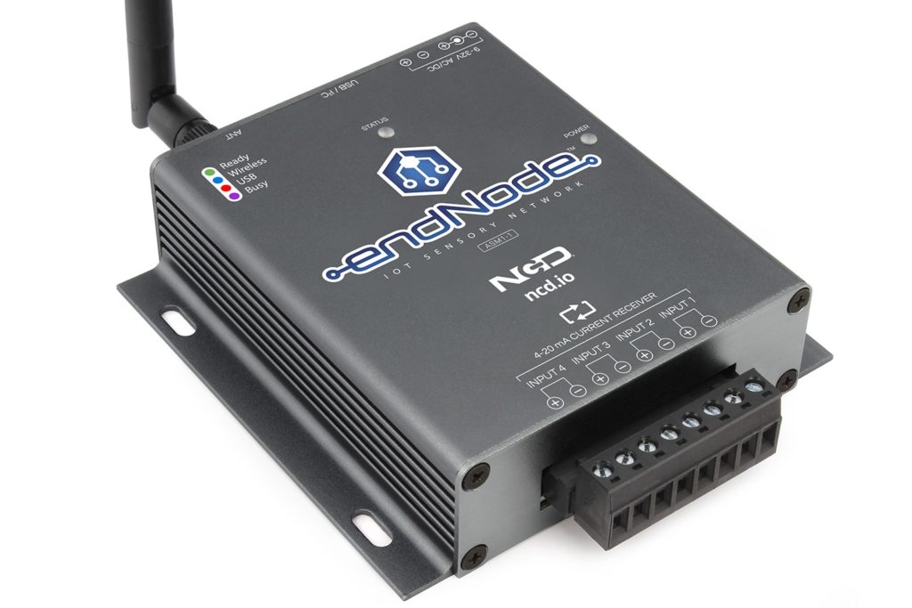
4-20mA Input 4-Channel endNode Introduction
The ASM1-1 is a 4-Channel 4-20mA Input endNode device, capable of reading 4-20mA sensors using a USB and Long Range Wireless Communications. endNodes were designed to communicate to computers, servers, gateways, PLCs, and embedded computers by offering a simple serial communications protocol. NCD endNodes were designed to retrofit traditional 4-20mA sensors into modern IoT installations. endNodes have many unique benefits over competing devices as they offer unlimited hardware expansion options. At the heart of NCD endNode devices is our custom communications endNode processor. This processor essentially converts serial communications to I2C communications. Since nearly every sensor in the world communicates using the I2C bus, NCD endNode devices may be expanded to communicate with all of today’s most modern sensors and controllers while offering forward compatibility with sensors and controllers, not yet developed, and without the need for firmware upgrades.

Wireless 4-20mA Input
endNodes support long-range wireless communications, making them ideal for wireless 4-20mA input applications. We have implemented 900MHz wireless communications in our endNode devices, as we know these devices will be installed in factory floors. We have a strong preference for using 900MHz in industrial applications, as we have used this frequency in automotive manufacturing plants in excess of 1 mile in length without problems. We have also used 900MHz in areas that required heavy shielding, which is achievable with proper planning. Most importantly, wireless 4-10mA sensor data should be encrypted, which is standard feature with all endNode devices. NCD places a strong emphasis on security, and 4-20mA input devices are fully secure using 128-bit AES encryption, right out of the box using our default encryption keys. Users may change the encryption key as needed for specific installations.
endNode devices respond to multiple computers, servers, and PLCs, giving all remote devices access to a single Wireless 4-20mA input endNode. endNode devices wait for a command from a remote device and respond to that particular remote device. This “speak when spoken to” strategy makes it possible for many computers to ask the status of inputs simultaneously.
NCD endNode devices are also capable of wireless grouping. This allows large numbers of endNode devices to be installed on each floor of a high-rise building without interference between floors. Ideally, every floor should have it’s own modem or gateway, allowing NCD endNode devices to scale to massive installations.
USB 4-20mA Input
All endNode devices are equipped with USB port. The USB Port may be used to read 4-20mA inputs, but also provides a mechanism of device configuration. NCD follows a strict set of rules regarding device configuration for the purposes of security. endNode devices cannot be reconfigured remotely as part of our security strategy. Vital configuration changes require the USB port. So the USB port on endNode devices may be used for daily use or it may be used for device configuration. endNode devices accept communications from both the Wireless and USB ports simultaneously, so it’s possible to connect a endNode device to a computer while remote computers are also capable of accessing the same endNode device.
Reading 4-20mA Input Channels
endNode devices were designed to be easy to use. Simply send a few bytes of data to the ASM1-1 and the endNode will report the 4-20mA input value of 1, 2, 3, or all 4 inputs at one time. It could not be easier. Every endNode controller is equipped with a USB port. We suggest plugging this port into a modern Window 10 computer when working with endNode controllers for the first time. Our windows software will demonstrate the functionality of endNode devices in about 5 minutes.
Below you will see a wiring diagram for how to connect endNode devices to your 4-20mA sensors:
USB Communications
Step 1: Download and Install Alpha Station
If you have not done so, now is a good time to download and install Alpha Station on your Windows 10 computer. Alpha Station is required for device configuration and serves as reference software for testing all endNode devices. We do not recommend the purchase or use of endNode devices without Alpha Station installed on at least one computer. Alpha Station is not required for daily use, but it is an essential tool for device configuration and learning. You may download and install Alpha Station from https://ncd.io/alpha (link opens in a new window).
Step 2: Plug in the USB Port
Before we get into wireless, we advise starting with USB communications. Wireless will be covered later, but for now, our objective is to make sure the necessary drives are working and make sure communications is possible. We also would like for you to see the device in operation as quickly as possible. The endNode device should mount as a virtual COM port on your computer. In the screenshot below, make sure your communication settings look similar to what is shown. Please note that COM58 will probably not be the same on your computer.
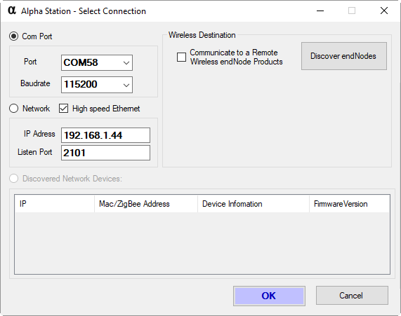
When running Alpha Station, simply select the COM port of the endNode device. If all goes well, you should see a window that looks similar to the one shown below, so go ahead on click on “PR53-6 4-Channel 0-20mA/0-40mA Receiver” as highlighted in Blue.
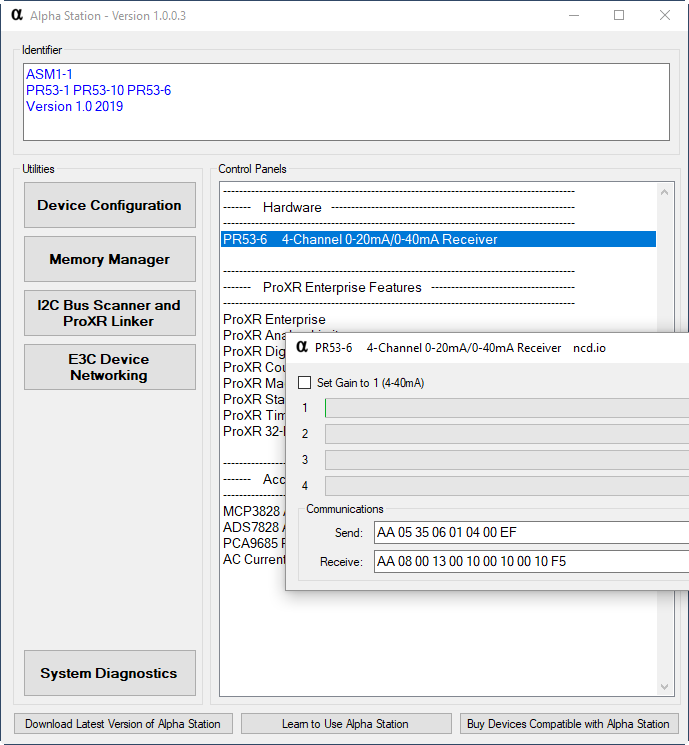
Step 3: Read 4-20mA Input Channels
The 4-20mA Input Control Panel will display the current readings on all 4 inputs.

Wireless Communications
Before we get started talking to a endNode using wireless communications, you are going to need a wireless modem to convert data from your computer to wireless data for the endNode. We currently offer 3 modem options, make sure you have one of the 3 modems shown below:
 |
| ||
 |
|
Step 1: Wireless Serial Number
Now that you have the ASM1-1 working over USB, let’s talk to the device using wireless communications. To get started, look carefully at the enclosure of the ASM1-1 endNode. You will see a sticker with the serial number printed on the back side. This serial number is required for wireless communications. This serial number is how we will identify each ASM1-1 endNode controller. No two endNode devices will ever have the same serial number, so keep track of these serial numbers so you have wireless access to your endNode ecosystem. We suggest keeping track of the serial number, the installation location, the network ID, and the encryption key (if you choose not to use the default key).
Step 2: Connect a Wireless Modem
Connect a wireless modem to your computer. You may choose USB, Ethernet, WiFi, Bluetooth (Virtual COM Port), but for the purposes of this tutorial, we will be using a USB Wireless Modem to access a endNode device.
Step 3: Run Alpha Station
Alpha Station is capable of communicating to endNode devices over wireless communications as well. It’s important to setup Alpha Station to use the Serial Number as mentioned in step 4. To do this, make sure “Communicate to a Remote Wireless endNode” is checked and the “Destination Address of Remote Node” matches the serial number printed on your endNode device.

Step 4: Read Wireless 4-20mA Inputs
You should now be able to read all four 4-20mA input channels over wireless communications. If you experienced any communication problems, try exiting and running Alpha Station again.
ASM1-1 Command Set
Reading Wireless 4-20mA Input Channels
Hopefully you followed both tutorials shown above. If so, take a look at the two screen shots below:
USB 4-20mA Communications Command Structure

Wireless 4-20mA Communications Command Structure
You will notice the USB commands are slightly different than the wireless commands. USB does not require a serial number for communications, so the protocol is slightly different. These windows will help you understand the commands required for communicating to endNode devices using your own software. Simply send these commands to the endNode device (Hex Bytes) and you will be reading wireless 4-20mA inputs in no time.
Every byte used for communicating to NCD endNodes has a meaning and a purpose. This section will help explain the specific commands supported by the ASM1-1 endNode. Please note that many more commands are supported by the ASM1-1, these common commands are explained in other documents. This guide will explain the commands that are unique to the ASM1-1 for the purposes of reading 4-20mA input channels.
The API Calculator is Required
Before we dive into the command set, the protocol for communications is very carefully controlled to reduce the possibility of communication errors. The overall format for communicating to endNodes is covered in the API Calculator, this is a REQUIRED tool for understanding the overall byte structure of all endNode commands. We will not cover this protocol in this document, as this is covered in great detail on the API Calculator page. We will make many references to this calculator in the command set below, the commands will not work unless properly encoded, so be SURE to use the API Calculator to encode the commands shown below.
4-20mA Input Commands
The ASM1-1 is a “speak when spoken to” device supporting a single command for reading 4-20mA inputs using two parameters. When sending the Read channel command, the device will sample the inputs and return a 16-bit result. The Channel parameters for reading channel inputs are required. The first parameter is the “Start Channel” and the second parameter is the “Stop Channel”. For instance, a Start Channel of 1 and a Stop Channel of 4 will direct the ASM1-1 to read the 4-20mA input values on all four input channels and return a single result. To read a single channel, simply use the same value for the Start and Stop channels. Valid parameter inputs for the AMS1-1 are 1 to 4 for each of the 4 input channels. Be sure to use the API Calculator, as the commands shown below must be encoded for proper operation.
Reading 4-20mA Input Channels 1 through 4
To read all 4 input channels, send the following bytes:
Function: Read 4-20mA Input Channels 1-4
Format: 0x35, 0x06, Start_Channel, Stop_Channel, Range_Option
Parameter: Start_Channel Valid Range 1 to 4
Parameter: Stop_Channel Valid Range 1 to 4
Parameter: Range_Option 0 = 0-20mA 1 = 0-40mA
Usage: Start_Channel Should be Lower or Equal to Stop_Channel
Send: 0x35, 0x06, 0x01, 0x04, 0x00
Receive: 0x00, 0x0F, 0x00, 0x0D, 0x00, 0x0A, 0x00, 0x0B
Note: See the API Calculator to Encode/Decode these Commands
The controller will return 4-20mA data by sending 8 payload bytes as shown above. Data is formatted as shown below:
MSB Channel 1, LSB Channel 1, MSB Channel 2, LSB Channel 2, MSB Channel 3, LSB Channel 3, MSB Channel 4, LSB Channel 4
| Channel 1 | Channel 2 | Channel 3 | Channel 4 | ||||||||||||||||
|
|
|
|
Now it’s time to convert the returned values into real-world 4-20mA values. We will use the following formula to convert the byte values to 4-20mA values:
4-20mA Value = ((MSB * 256)+LSB) * 0.0013568521031208
4-40mA Value = ((MSB * 256)+LSB) * (0.0013568521031208 / 2)
Note: Analog Values will Fluctuate Slightly, this is Normal Operation