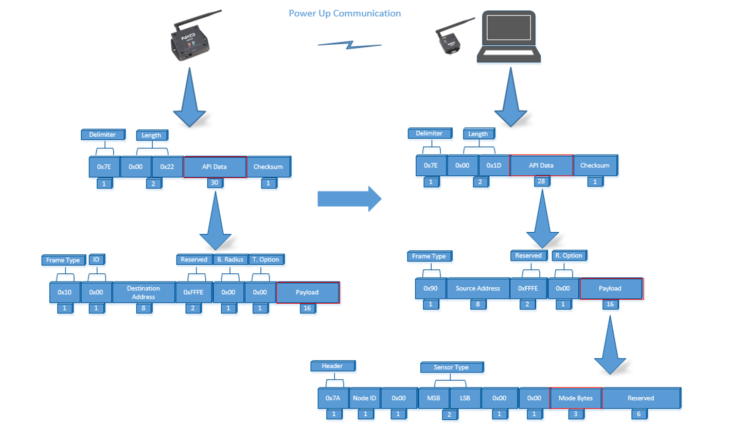
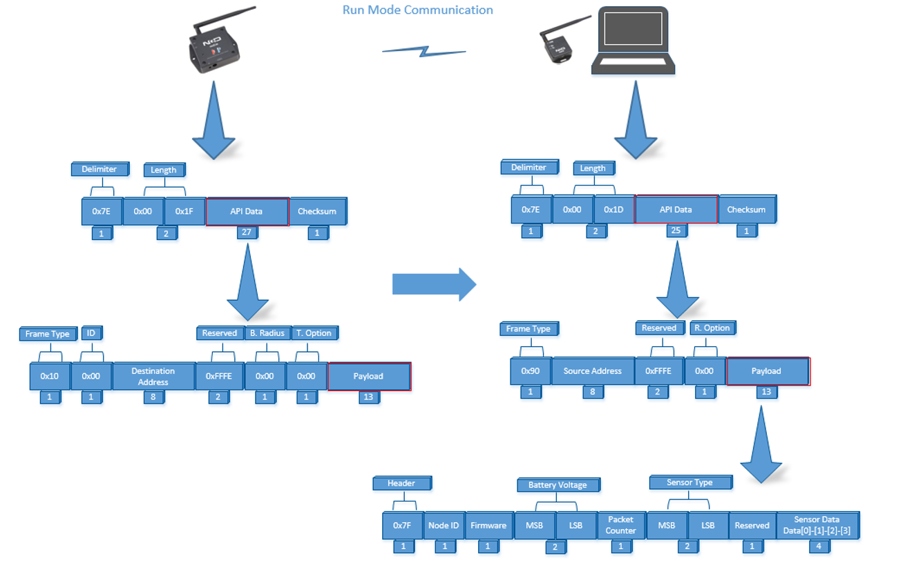
Wireless IoT Soil Moisture Temperature Conductivity Sensor Product Manual

NCD's Long Range Industrial IoT Wireless Soil Moisture Temperature EC Sensor

Features

  • Wireless Soil Moisture Temperature EC Sensor for Indoor Outdoor Use
  • Industrial Grade 1 Channel IoT Soil Moisture Temperature EC Sensor
  • Temperature Range-30 ~ 70 ° C;0 ~ 100%( VWC)
  • EC Range 0~20000μs/cm
  • 2 Mile Line-of-Sight Range with On-Board Antenna
  • Probe Does Not Corrode Over Time and Insensitive to Salinity
  • Measures Volumetric Water Content (VWC)
  • Interface to Raspberry Pi, Microsoft® Azure®, Losant, and More
  • Example Software for Visual Studio and LabVIEW®
  • Wireless Mesh Networking using DigiMesh®
  • Open Communication Protocol for Easy Software Integration
  • Includes Battery Level with Every Transmission
  • Validates and Retries Lost Communication Packets
  • * USB Modem is recommended for Calibration and Sensor Setup

Applications

  • Environmental Science
  • Green House
  • Agriculture
  • Indoor Grow House

Description

Introducing NCD’s Long Range IoT Wireless Soil Moisture Temperature EC Sensor, boasting up to a 2 Mile range using a wireless mesh networking architecture.  This long range IoT wireless Soil Moisture Temperature EC sensor incorporates a stainless steel Soil probe that samples Soil Moisture Temperature EC level at user defined intervals and sends a wireless transmission to remote gateways and modems. After sampling, this device goes to sleep to minimize power consumption and prolong battery life. To minimize power consumption, it sleeps during the time it is not checking for change in soil moisture level. Both of these features work together, supporting multiple application areas in one package.

This wireless Soil Moisture Temperature EC sensor makes it possible to monitor soil moisture in multiple locations either outdoors or in greenhouses to monitor soil saturation conditions. The soil moisture measurement range is 0-100% and the EC measurement range is 0-20000us/cm.  The included probe is 10cm and the included cable is 3 Meters in length.

Powered by just 4 AA batteries and an operational lifetime of 500,000 wireless transmissions, a 10 years battery life can be expected depending on environmental conditions and the data transmission interval.  Optionally, this sensor may be externally powered.

Note : EC Should be calibrated for different type of Soils. 

To complete a network with an industrial sensor at one end, a USB Modem is required at the receiving end (PC end) that receives data from sensor. 

Getting Started

The sensor and Zigmo/Router come pre-programmed and work out of the box. In this section we will setup a sensor and Zigmo link and start receiving data on our PC. Though this guide shows how to visualize data on LabVIEW utility, you can also use a simple serial terminal to see raw data by following these steps.

Resources Required

Steps

  1. Power-up the Wireless Sensor and make sure its antenna is installed
  2. Connect your Zigmo/Router to your PC
Figure 1: Connect Zigmo/Router to PC
  1. Identify the serial port allocated to it by going into device manager (You can also find the serial port using Digi provided utility XCTU)

At this stage, both the Sensor and Zigmo have automatically established communication and the data can be read from the serial port at which Zigmo has been installed.

Figure 2: Serial port identification

Troubleshooting

Changed/Unknown setting at sensor end

One of the issues for unsuccessful communication can be a changed setting at the sensor end due to which the sensor and Zigmo are unable to establish a connection. You can resolve this problem by going back to the factory default settings which are provided in Table 1. Please refer to Figure 7 and follow steps shown in it for applying factory default settings.

Once the sensor resets it will start sending a frame every 600 seconds after factory reset.

Please refer to the detailed document available to Digi website to understand X-bee communication parameters and its operation mechanism.

Table 1: Default Parameters programmed after Factory reset sequence

Changed/Unknown setting at PC end

Sometimes a changed setting at Zigmo end, whether intentional or unintentional, can cause a network failure and no data reception at PC end. To fix this issue when the sensor end is operating at factory default settings you will have to bring the Zigmo/Router to factory default settings as well. For that, please download the configuration file for Zigmo from our website. You will also require XCTU utility provided by Digi.

After installing XCTU Utility, run it and go to add a radio module. Select the serial port at which Zigmo is connected and press finish. This will connect the Zigmo to XCTU.

Figure 5: Connecting Zigmo/Router to XCTU

After double clicking the added module, a list of parameters will be displayed on the right side. Select the load configuration file from the top and select configuration file form the location where you downloaded it earlier.

Now press the write button on top to write these parameters. Close the XCTU utility and open the LabVIEW utility and follow the steps in getting started section to communicate with sensor.

Figure 6: Loading a default profile to Zigmo/Router

Modes of Operation

This module incorporates 2 modes of operation, these are

  • Run Mode
  • Configuration Mode

Run mode is the standard mode, the module will always enter Run mode if no button is pressed during Power-up/Reset. Configuration mode is intended to configure sensor parameters and the X-bee parameters on the sensor end. Note that the Sensor end X-bee is only configurable via the sensor controller using the commands provided in device manual. Figure 7 illustrates these modes.

The device sends a startup packet which can be used to determine the mode in which it is operating. These packets are shown in Table 2.

Mode Selection Process

The CFG button on the module is used to change mode. If CFG button is pressed and the module reset button is pressed, the module will enter the configuration mode. The amount of time CFG button has to be pressed is shown in Figure 7.

Note that settings only take effect after the reset.

Figure 7: Mode Selection Process
Frame Communication at Power up

In figure 8,  Mode bytes highlighted in red can be compared with the values provided in Table 2 to determine the mode in which the sensor is operating. Node ID is the ID of the given sensor while sensor type determines the type of sensor. Both of these can be used to determine the exact sensor which is sending the information.

A shown in second column in Table 2, the sensor configures its PAN ID automatically depending upon the mode it is working in. During factory reset it sets the PAN ID to the value given in table therefore the factory reset frame will only be received if your Zigmo/Router PAN ID matches this ID. Please note that right after factory reset the sensor enters configuration mode therefore its PAN ID is changed again and a new frame is generated. All 3 type of frames are shown in Figure 9, Figure 10 and Figure 11.

The factory default settings are shown in Table 1. For parameter description please refer to the section on configuration.

Table 2: Mode Bytes for different sensor modes (* this frame is followed by configuration frame as shown Figure 7)
Figure 8: Typical Communication at Power Up, Transmitted packet (left) Received packet (right)
Figure 9: Run Mode Power up frame
Figure 10: Configuration Mode Power up frame
Figure 11: Factory Default Power up frame

Run Mode

Run mode is the default mode of operation of this sensor. In this mode the sensor sends periodic packets to destination receiver. During the time it is not sending packets, it sleeps and conserves power. Sensor end X-bee operates in API mode and sends packets to the saved destination address on the network specified by the saved PAN ID. Figure 12 illustrates an API packet transmission and reception.

Packet reception at receiver end is ensured by the device by retrying up to 3 times if no acknowledgement is received that the packet has been successfully received. The device uses the acknowledgement functionality available in API mode in X-bee devices therefore user does not need to worry about sending acknowledgements for every packet.

Figure 12: Transmit packet detail (left), Received packet detail (right)

The detail for API packet received at PC end can be read from the X-bee manual available from Digi. The detail of Payload section of packet is shown in Table 3.

Typical response from the device in Run mode is shown in Figure 13 and Figure 14. The utility shown in Figure 14 can be downloaded from the website.

Sensor Type == 69

Wireless 1 Channel Soil Temp Moisture and EC Sensor

The detail for API packet received at PC end can be read from the X-bee manual available from Digi. The detail of Payload section of packet is shown in Table 3.

ByteFunctionValueDescription
1Header07F
Header to differentiate various type of packets
2Node ID10x00 Factory DefaultNode ID to differentiate up to 256 nodes in a network. User configurable values
3Firmware2
Used to determine firmware version programmed in the device
4Battery Voltage MSB
5Battery Voltage LSBMSB 3, LSB 4
Sampled battery voltage of the device.

Battery Voltage=((Battery Voltage MSB x 256+Battery Voltage LSB) x 0.00322 V
Use this equation to calculate battery %.
Battery % = 0.537*ADC – 449.9
6Packet Counter5It is an 8-bit counter that increments with each packet transmission. It can be used to detect missing packets.
7
8Sensor TypeMSB 6, LSB 70x45Two bytes to determine sensor type. It can be used in conjunction with Node ID to create sensor networks of up to 256 nodes for a single type of sensor and multiple such networks can coexist and can be differentiated in processing software on PC end
9Reserved8
For future use
14Sensor Data/ Soil Moisture9/Data[0], 10/Data[1],11/Data[2], 12/Data[3]Soil Moisture %

Soil Moisture = ( Data[0]<<24+Data[1]<<16+Data[2]<<8+ Data[3])/100.00
15Sensor Data/ Soil Temperature 13/Data[4], 14/Data[5],15/Data[6], 16/Data[7]Soil Temperature in C

Soil Temp = ( Data[4]<<24+Data[5]<<16+Data[6]<<8+ Data[7])/100.00
16Sensor Data/ Soil EC17/Data[8], 18/Data[9],19/Data[10], 20/Data[11]Soil Electrical Conductivity

Soil EC = ( Data[8]<<24+Data[9]<<16+Data[10]<<8+ Data[11])/100.00
17Sensor Data/ Soil Salinity 21/Data[12], 22/Data[13],23/Data[14], 24/Data[15]Soil Salinity

Soil SAL = ( Data[12]<<24+Data[13]<<16+Data[14]<<8+ Data[15])/100.00

Sensor Type == 71

Wireless 3 Channel Soil Temp Moisture and EC Sensor

ByteFunctionValueDescription
1Header07F
Header to differentiate various type of packets
2Node ID10x00 Factory DefaultNode ID to differentiate up to 256 nodes in a network. User configurable values
3Firmware2
Used to determine firmware version programmed in the device
4Battery Voltage MSB
5Battery Voltage LSBMSB 3, LSB 4
Sampled battery voltage of the device.

Battery Voltage=((Battery Voltage MSB x 256+Battery Voltage LSB) x 0.00322 V
Use this equation to calculate battery %.
Battery % = 0.537*ADC – 449.9
6Packet Counter5It is an 8-bit counter that increments with each packet transmission. It can be used to detect missing packets.
7
8Sensor TypeMSB 6, LSB 70x47Two bytes to determine sensor type. It can be used in conjunction with Node ID to create sensor networks of up to 256 nodes for a single type of sensor and multiple such networks can coexist and can be differentiated in processing software on PC end
9Reserved8
For future use
14Sensor Data/ Soil Moisture9/Data[0], 10/Data[1],11/Data[2], 12/Data[3]Soil Moisture %

Soil Moisture = ( Data[0]<<24+Data[1]<<16+Data[2]<<8+ Data[3])/100.00
15Sensor Data/ Soil Temperature 13/Data[4], 14/Data[5],15/Data[6], 16/Data[7]Soil Temperature in C

Soil Temp = ( Data[4]<<24+Data[5]<<16+Data[6]<<8+ Data[7])/100.00
16Sensor Data/ Soil EC17/Data[8], 18/Data[9],19/Data[10], 20/Data[11]Soil Electrical Conductivity

Soil EC = ( Data[8]<<24+Data[9]<<16+Data[10]<<8+ Data[11])/100.00
17Sensor Data/ Soil Salinity 21/Data[12], 22/Data[13],23/Data[14], 24/Data[15]Soil Salinity

Soil SAL = ( Data[12]<<24+Data[13]<<16+Data[14]<<8+ Data[15])/100.00
18Sensor Data/ Soil Moisture 225/Data[0], 26/Data[1],27/Data[2], 28/Data[3]Soil Moisture %

Soil Moisture = ( Data[0]<<24+Data[1]<<16+Data[2]<<8+ Data[3])/100.00
19Sensor Data/ Soil Temperature 29/Data[4], 30/Data[5],31/Data[6], 32/Data[7]Soil Temperature in C

Soil Temp = ( Data[4]<<24+Data[5]<<16+Data[6]<<8+ Data[7])/100.00
20Sensor Data/ Soil EC31/Data[8], 32/Data[9],33/Data[10], 34/Data[11]Soil Electrical Conductivity

Soil EC = ( Data[8]<<24+Data[9]<<16+Data[10]<<8+ Data[11])/100.00
21Sensor Data/ Soil Salinity 35/Data[12], 36/Data[13],37/Data[14], 38/Data[15]Soil Salinity

Soil SAL = ( Data[12]<<24+Data[13]<<16+Data[14]<<8+ Data[15])/100.00
22Sensor Data/ Soil Moisture 339/Data[0], 40/Data[1],41/Data[2], 42/Data[3]Soil Moisture %

Soil Moisture = ( Data[0]<<24+Data[1]<<16+Data[2]<<8+ Data[3])/100.00
23Sensor Data/ Soil Temperature 43/Data[4], 44/Data[5],45/Data[6], 46/Data[7]Soil Temperature in C

Soil Temp = ( Data[4]<<24+Data[5]<<16+Data[6]<<8+ Data[7])/100.00
24Sensor Data/ Soil EC47/Data[8], 48/Data[9],49/Data[10], 50/Data[11]Soil Electrical Conductivity

Soil EC = ( Data[8]<<24+Data[9]<<16+Data[10]<<8+ Data[11])/100.00
25Sensor Data/ Soil Salinity 51/Data[12], 52/Data[13],53/Data[14], 54/Data[15]Soil Salinity

Soil SAL = ( Data[12]<<24+Data[13]<<16+Data[14]<<8+ Data[15])/100.00

Typical response from the device in Run mode is shown in Figure 13 and Figure 14. The utility shown in Figure 14 can be downloaded from the website.

Sensor Type == 72

Wireless 1 SDI Channel Soil Temp Moisture and EC Sensor

The detail for the API packet received at the PC end can be read from the X-bee manual available from Digi. The detail of the Payload section of the packet is shown in Table 3.

ByteFunctionValueDescription
1Header07F
Header to differentiate various type of packets
2Node ID10x00 Factory DefaultNode ID to differentiate up to 256 nodes in a network. User configurable values
3Firmware2
Used to determine firmware version programmed in the device
4Battery Voltage MSB
5Battery Voltage LSBMSB 3, LSB 4
Sampled battery voltage of the device.

Battery Voltage=((Battery Voltage MSB x 256+Battery Voltage LSB) x 0.00322 V
Use this equation to calculate battery %.
Battery % = 0.537*ADC – 449.9
6Packet Counter5It is an 8-bit counter that increments with each packet transmission. It can be used to detect missing packets.
7
8Sensor TypeMSB 6, LSB 70x48Two bytes to determine sensor type. It can be used in conjunction with Node ID to create sensor networks of up to 256 nodes for a single type of sensor and multiple such networks can coexist and can be differentiated in processing software on PC end
9Reserved8
For future use
10Sensor Data/ Soil Temperature 9/Data[0], 10/Data[1]Soil Temperature in C
Soil Temp = ( Data[0]<<8+Data[1]/100.00
12Sensor Data/ Soil Moisture11/Data[2], 12/Data[3]Soil Moisture %
Soil Moisture = ( Data[2]<<8+Data[3]/100.00
14Sensor Data/ Soil Bulk EC13/Data[4], 14/Data[5]Soil Bulk EC uS/cm
Soil Bulk EC = ( Data[0]<<8+Data[1]
16Sensor Data/ Soil Pore EC15/Data[6], 16/Data[7]Soil Pore EC uS/cm
Soil Pore EC = ( Data[0]<<8+Data[1]
18Sensor Data/ Soil Permittivity17/Data[2], 18/Data[3]Soil Permittivity (1-100)

Permittivity = ( Data[0]<<8+Data[1]/100.00

Sensor Type == 77

Wireless 3 SDI Channel Soil Temp Moisture and EC Sensor

The detail for the API packet received at the PC end can be read from the X-bee manual available from Digi. The detail of the Payload section of the packet is shown in Table 3.

3 Channel SDI Soil Moisture temperature EC Sensor — Type 77

ByteFunctionValueDescription
1Header07F
Header to differentiate various type of packets
2Node ID10x00 Factory DefaultNode ID to differentiate up to 256 nodes in a network. User configurable values
3Firmware2
Used to determine firmware version programmed in the device
4Battery Voltage MSB
5Battery Voltage LSBMSB 3, LSB 4
Sampled battery voltage of the device.

Battery Voltage=((Battery Voltage MSB x 256+Battery Voltage LSB) x 0.00322 V
Use this equation to calculate battery %.
Battery % = 0.537*ADC – 449.9
6Packet Counter5It is an 8-bit counter that increments with each packet transmission. It can be used to detect missing packets.
7
8Sensor TypeMSB 6, LSB 70x48Two bytes to determine sensor type. It can be used in conjunction with Node ID to create sensor networks of up to 256 nodes for a single type of sensor and multiple such networks can coexist and can be differentiated in processing software on PC end
9Reserved8
For future use
10Sensor Data/ Soil Temperature 9/Data[0], 10/Data[1]Soil Temperature in C
Soil Temp = ( Data[0]<<8+Data[1]/100.00
12Sensor Data/ Soil Moisture11/Data[2], 12/Data[3]Soil Moisture %
Soil Moisture = ( Data[2]<<8+Data[3]/100.00
14Sensor Data/ Soil Bulk EC13/Data[4], 14/Data[5]Soil Bulk EC uS/cm
Soil Bulk EC = ( Data[0]<<8+Data[1]
16Sensor Data/ Soil Pore EC15/Data[6], 16/Data[7]Soil Pore EC uS/cm
Soil Pore EC = ( Data[0]<<8+Data[1]
18Sensor Data/ Soil Permittivity17/Data[8], 18/Data[9]Soil Permittivity (1-100)

Permittivity = ( Data[0]<<8+Data[1]/100.00
20Sensor Data/ Soil Temperature 19/Data[10], 20/Data[11]Soil Temperature in C
Soil Temp = ( Data[0]<<8+Data[1]/100.00
22Sensor Data/ Soil Moisture21/Data[12], 22/Data[13]Soil Moisture %
Soil Moisture = ( Data[2]<<8+Data[3]/100.00
24Sensor Data/ Soil Bulk EC23/Data[14], 24/Data[15]Soil Bulk EC uS/cm
Soil Bulk EC = ( Data[0]<<8+Data[1]
26Sensor Data/ Soil Pore EC25/Data[16], 26/Data[17]Soil Pore EC uS/cm
Soil Pore EC = ( Data[0]<<8+Data[1]
28Sensor Data/ Soil Permittivity27/Data[18], 28/Data[19]Soil Permittivity (1-100)

Permittivity = ( Data[0]<<8+Data[1]/100.00
30Sensor Data/ Soil Temperature 29/Data[20], 30/Data[21]Soil Temperature in C
Soil Temp = ( Data[0]<<8+Data[1]/100.00
32Sensor Data/ Soil Moisture31/Data[22], 32/Data[23]Soil Moisture %
Soil Moisture = ( Data[2]<<8+Data[3]/100.00
34Sensor Data/ Soil Bulk EC33/Data[24], 34/Data[25]Soil Bulk EC uS/cm
Soil Bulk EC = ( Data[0]<<8+Data[1]
36Sensor Data/ Soil Pore EC35/Data[26], 36/Data[27]Soil Pore EC uS/cm
Soil Pore EC = ( Data[0]<<8+Data[1]
38Sensor Data/ Soil Permittivity37/Data[28], 38/Data[29]Soil Permittivity (1-100)

Permittivity = ( Data[0]<<8+Data[1]/100.00

Figure 13: Run mode packets being received in a terminal (Hex mode)

Configuration Mode

Configuration mode is intended to setup the device over the wireless link. Entering configuration mode was already explained in the section “mode selection procedure”. User can also setup X-bee communication and networking parameters using this mode via PC. Note that settings only take effect after reset and are stored inside the device.

In configuration mode, the device sets its X-bee pan id to 7BCD (Hex). Also, the destination address used by the sensor is broadcast (0000FFFF). This ensures that once you put a device in configuration mode you just need to change the PAN ID of your Zigmo to match with sensor and start configuring your device. You can change the PAN ID of your Zigmo using XCTU from Digi. If you use our LabVIEW utility, it will automatically change Zigmo PAN ID once you open the configuration window. When you exit this window your PAN ID will be restored to old value.

A standard configuration packet and its fields are explained in Figure 15. Its possible responses are also shown. The commands supported by this sensor are shown in Table 4, these can be used in the Parameters field of Payload section. The sensor responds to these commands with an acknowledgement if the process completed successfully or with an error if it failed to setup a parameter. The respective Data and Reserve section length and values are shown in Table 5 for the case of acknowledgement. In the case of error, the reserved section will be fixed and not used, while the Error number byte will determine the type of error returned. These errors are mentioned in Table 6.

Figure 15 depicts standard communication between Zigmo/Router and sensor. Sensor commands have variable length frames whereas responses received from sensor are fixed length. The 2 scenarios are also shown, where a command can result in an acknowledgement reception or an error reception at the Zigmo end.

Examples for setting parameters in configuration mode are shown in Appendix A.

Figure 15: Configuration mode communication
Table 4: Configuration Commands and their respective headers, sub command and Parameter field
Table 5: Acknowledgment data for various commands and the size of reserve section in each case
Table 6: Error numbers and their description

Appendix A

Configuration Commands

1. Set Broadcast Transmission

Command For COPY:  7E00 1310 0000 0000 0000 00FF FFFF FE00 00F7 0100 0001 FB

2. Set ID and Delay

Command For COPY: 7E 00 17 10 00 00 00 00 00 00 00 FF FF FF FE 00 00 F7 02 00 00 01 00 00 00 04 F6

3. Set Destination Address

Command For COPY: 7E00 1710 0000 0000 0000 00FF FFFF FE00 00F7 0300 0001 1234 5678 E5

4. Set Power

Command For COPY: 7E00 1410 0000 0000 0000 00FF FFFF FE00 00F7 0400 0001 02F6

5. Set PANID

Command For COPY: 7E00 1510 0000 0000 0000 00FF FFFF FE00 00F7 0500 0001 7CDE 9D

6. Set Retries

Command For COPY: 7E00 1410 0000 0000 0000 00FF FFFF FE00 00F7 0600 0001 03F3

7. Read Delay

Command For COPY: 7E00 1410 0000 0000 0000 00FF FFFF FE00 00F7 0600 0001 03F3

8. Read Power

Command For COPY: 7E00 1310 0000 0000 0000 00FF FFFF FE00 00F7 1600 0001 E6

9. Read Retries

Command For COPY: 7E00 1310 0000 0000 0000 00FF FFFF FE00 00F7 1700 0001 E5

10. Read Destination Address

Command For COPY:  7E00 1310 0000 0000 0000 00FF FFFF FE00 00F7 1800 0001 E4

11. Read PANID

Command For COPY:  7E00 1310 0000 0000 0000 00FF FFFF FE00 00F7 1900 0001 E3

12. Enable Encryption

Command For COPY:  7E00 1310 0000 0000 0000 00FF FFFF FE00 00F2 0100 0001 00

13. Disable Encryption

Command For COPY:  7E00 1310 0000 0000 0000 00FF FFFF FE00 00F2 0200 0001 FF

14. Set Encryption Key

Command For COPY: 7E00 2410 0000 0000 0000 00FF FFFF FE00 00F2 0300 0001 0011 2211 2211 2211 2233 4433 4433 4433 4456

15. Sensor Soil Moisture Calibration

Set Multiplication Factor 

7E 00 18 10 00 00 00 00 00 00 00 FF FF FF FE 00 00 F4 4F 00 00 45 01 00 00 00 FA 71

Command — F4 4F 00 00 45 01 00 00 00 FA

0xF4 — Header

0x4F — Sub command

00 — Node ID

00,45 — Sensor type

01 — Sub parameter

00,00,00,0xFA — Set Multiplication factor to 2.5

Get Multiplication Factor 

7E 00 14 10 00 00 00 00 00 00 00 FF FF FF FE 00 00 F4 50 00 00 45 01 6A

Set Off Set Factor 

7E 00 18 10 00 00 00 00 00 00 00 FF FF FF FE 00 00 F4 51 00 00 45 01 00 00 02 8A DD

Command — F4 51 00 00 45 01 00 00 02 8A

0xF4 — Header

0x51 — Sub command

00 — Node ID

00,50 — Sensor type

01 — Sub parameter

00,00,02,8A — Set offset value to 6.5

Get Offset Factor 

7E 00 14 10 00 00 00 00 00 00 00 FF FF FF FE 00 00 F4 52 00 00 45 01 68

Soil Moisture calibration is an extremely important step. If calibration is not done properly it can lead to incorrect results.

Calibration steps —

  1. Install the sensor and meter to same height
  2. Read Soil Moisture using sensor and Meter
  3. Note down these readings and take one more reading at a different soil moisture level
  4. using these 4 data points calculate the slope ( multiplication) and constant ( offset) of a linear equation 
  5. Store these new offset and multiplication factor values in the sensor 

16. Sensor Soil Temperature Calibration

Set Multiplication Factor 

7E 00 18 10 00 00 00 00 00 00 00 FF FF FF FE 00 00 F4 4F 00 00 45 02 00 00 00 FA 70

Command — F4 4F 00 00 45 02 00 00 00 FA

0xF4 — Header

0x4F — Sub command

00 — Node ID

00,45 — Sensor type

02 — Sub parameter

00,00,00,0xFA — Set Multiplication factor to 2.5

Get Multiplication Factor 

7E 00 14 10 00 00 00 00 00 00 00 FF FF FF FE 00 00 F4 50 00 00 45 02 69

Set Off Set Factor 

7E 00 18 10 00 00 00 00 00 00 00 FF FF FF FE 00 00 F4 51 00 00 45 02 00 00 02 8A DA

Command — F4 51 00 00 45 02 00 00 02 8A

0xF4 — Header

0x51 — Sub command

00 — Node ID

00,50 — Sensor type

02 — Sub parameter

00,00,02,8A — Set offset value to 6.5

Get Offset Factor 

7E 00 14 10 00 00 00 00 00 00 00 FF FF FF FE 00 00 F4 52 00 00 45 02 66

Soil temperature calibration is an extremely important step. If calibration is not done properly it can lead to incorrect results.

Calibration steps —

  1. Install the sensor and meter to same height
  2. Read Soil temperature using sensor and Meter
  3. Note down these readings and take one more reading at a different temperature level
  4. using these 4 data points calculate the slope ( multiplication) and constant ( offset) of a linear equation 
  5. Store these new offset and multiplication factor values in the sensor 

17. Sensor Soil EC Calibration

Set Multiplication Factor 

7E 00 18 10 00 00 00 00 00 00 00 FF FF FF FE 00 00 F4 4F 00 00 45 03 00 00 00 FA 6F

Command — F4 4F 00 00 45 02 00 00 00 FA

0xF4 — Header

0x4F — Sub command

00 — Node ID

00,45 — Sensor type

03 — Sub parameter

00,00,00,0xFA — Set Multiplication factor to 2.5

Get Multiplication Factor 

7E 00 14 10 00 00 00 00 00 00 00 FF FF FF FE 00 00 F4 50 00 00 45 03 68

Set Off Set Factor 

7E 00 18 10 00 00 00 00 00 00 00 FF FF FF FE 00 00 F4 51 00 00 45 03 00 00 02 8A CF

Command — F4 51 00 00 45 03 00 00 02 8A

0xF4 — Header

0x51 — Sub command

00 — Node ID

00,50 — Sensor type

03 — Sub parameter

00,00,02,8A — Set offset value to 6.5

Get Offset Factor 

7E 00 14 10 00 00 00 00 00 00 00 FF FF FF FE 00 00 F4 52 00 00 45 03 65

Soil EC calibration is an extremely important step. If calibration is not done properly it can lead to incorrect results.

Calibration steps —

  1. Install the sensor and meter to same height
  2. Read Soil EC using sensor and Meter
  3. Note down these readings and take one more reading at a different temperature level
  4. using these 4 data points calculate the slope ( multiplication) and constant ( offset) of a linear equation 
  5. Store these new offset and multiplication factor values in the sensor 

19. Super Command

The super command can be used to configure some sensor parameters during run mode.

In order to set parameters like Delay, node id and other sensor related parameters the super command needs to be be enabled in the cfg mode.

Super command enable counter —

By sending this command users can set a counter after which sensor will stay awake for 2 sec and wait for a command from the user. if it does not get command withing 2 sec it will go back to sleep. 

Command For COPY: 7E 00 14 10 00 00 00 00 00 00 00 FF FF FF FE 00 00 F7 30 00 00 00 03 CA


In above command we are setting the super command enable counter to 3. After every 3 data transmission the sensor will stay awake for 2 sec and wait for any cfg command from the user. 


Read super command counter Value

Command For COPY:  7E 00 14 10 00 00 00 00 00 00 00 FF FF FF FE 00 00 F7 31 00 00 00 00 CC

Appendix B

Frame Checksum Calculation

In order to successfully communicate over the API protocol, checksum is of vital importance. The X-bee at either end will reject packets if the checksum is not matched. Checksum is also checked by the sensor controller and LabVIEW utility for added security.

For sending packets, checksum calculation works as follows

  1.  Not including the frame delimiter and length, add all the bytes and keep the lower 8 bits of result
  2.  Subtract this value from 0xFF (hex)
  3. The resultant value is the checksum
  4. Append this byte to the original packet for sending

Consider the example for the command Set Broadcast shown in Figure 19 in A APPENDIX and see that the calculated checksum matches with the checksum sent by the terminal/LabVIEW

Although checksum is matched by the X-bee itself, but for understanding follow these steps to match checksum at reception

  1. Not including the frame delimiter and length, add all the bytes including the received checksum
  2. Keep only the last 8 bits
  3. If the result is 0xFF, the checksum is correct and the packet can be processed.

Consider the example of the command Set Broadcast shown in Figure 19 in A APPENDIX and see that the received packet checksum verifies since the result is 0xFF.