The NCD RS-485 Communications module make it easy to implement select NCD devices onto a RS-485 bus. RS-485 is a hardware networking protocol, implementation (selection of devices on the network) requires a software networking protocol. Many NCD Industrial devices include the E3C command set, which allows users to select an active device on the RS-485 bus. Using the RS-485 hardware protocol and the NCD E3C protocol together makes it easy to implement up to 256 devices on the RS-485 bus. Devices are connected together up to 4,000 feet using just 3 communication wires daisy-chained between devices. A master RS-485 device talks to the 256 slave devices with a typical communication speed of 9600 baud.
This guide will demonstrate the use of our FT232RL USB to RS-485 converter as well as 3 node devices chained together.
USB to RS-485 Converter: RS-485 Serial Communications Converter with USB Interface FT232RL SN65HVD12D
Node devices in this tutorial will include NCD ProXR relay controllers with a RS-485 node communications module installed.
RS-485 Node Module: RS-485 Node Serial Network Communications Module SN65HVD12D
Both USB to RS-485 Converter and RS-485 Node Modules use the Texas Instruments SN65HVD12D RS-485 driver chip, greatly simplifying implementation. NCD RS-485 communications hardware is compatible with other products outside the NCD family. Our products completely handle the hardware implementation of the RS-485 protocol. Should use choose to use our products outside the NCD family, a software protocol for addressing multiple devices will be required. We use our own E3C command set for our addressing protocol, you could implement our E3C command set or develop your own command set specific to your hardware.
The following diagram demonstrates how to connect the hardware together:
NCD RS-485 Node modules are a modular technology, allowing most NCD devices to be retrofitted with RS-485 communication capabilities. Node modules have a number of options and jumper settings available, allowing you to adapt the module in a number of ways. NCD Node modules are preconfigured for RS-485 communications at 9600 baud. Node modules communicate to the host device at 57.6k baud by default. Baud rate settings are programmable via RS-485. The C jumper must be installed for configuration. The node module must power-up with the C jumper installed. Similarly, once configuration is complete, the node module must be powered up with the C jumper removed for proper operation.

This guide will demonstrate implementation of our RS-485 hardware using NCD ProXR series relay controllers. We will network 3 devices onto the RS-485 bus and talk to each one individually.
Base Station software will allow you to configure and test all devices in just a few minutes. Start by installing Base Station software on your Windows 8 or 10 computer. Download the latest version of Base Station from: https://ncd.io/start
Connect a Single ProXR Device
Connect a single ProXR relay controller to your computer. We need to program the E3C device number into each controller. You can program the E3C device number using RS-485 or using any other communications module you have available. If you choose to program the E3C device number using RS-485, make sure to connect only 1 device at a time during the programming process. Also note that you need to setup Base Station communications at 9600 Baud, not the default 115.2K Baud. Baud rate is changed on the first screen you see when running Base Station. Once connected to the controller, perform the following tasks in order:
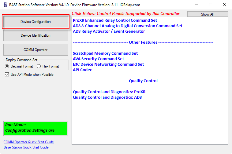
Click on “Device Configuration Button” highlighted above.

Important: Be sure to change the Baud rate setting from 115.2K Baud to 57.6K (no shown in photo above).
Set the E3C Device number. The default E3C device number is 0. Make sure each controller has a different device number. It is very helpful to label each controller with its device number to prevent confusion. Once the E3C device number is set, click the “Store Configuration” button in the lower right corner. Program every E3C device with a unique device number before proceeding.
Now it’s time to get all the controllers on the RS-485 bus. Wire up each of the communication modules as shown in the first diagram on this tutorial. Power up all the devices. We will use Comm Operator, a utility within Base Station to send commands to each device individually. Comm Operator is very much like a terminal program, as it makes it easy to send and receive using serial communications.

Follow these steps carefully:
- Run Base Station Software
- Choose “9600” for the Baud Rate
- Click the “MORE” Button (It will change to “LESS” when clicked)
- Click on the “Comm Operator” Button

When the Comm Operator screen software opens, follow these steps:
- Click the “API Mode” Check box. This will convert your commands into API Mode, used for speed and reliability. This step is really only required for Fusion series controllers, but should be considered best practice for all ProXR, Fusion, and Taralist series controllers.
- Type 254 47 0 0 1 into the Quick Send box. This command is used to toggle the first relay on your relay controller. This is a great command to test with because the first relay will toggle every time the command is received.
- Test the Toggle command by clicking the “Send” button. Send the command a few times to make sure the relay toggles.
- The “Log Data” box will send your command in API format and receive data will be displayed in Blue (also in API Format).

Now that we have the relay toggling, we need to choose which device is going to receive the toggle command. We will use one simple E3C command to direct your command to a specific device. In this sample, we will direct all commands to E3C device number 3. You may want to change the device number to a different device number, depending on which devices are available on your network. Follow these steps:
- In the “Quick Send” box, enter: 254 252 3
- Click the “Send” button
- The “Log Data” window will display the command and the response. The response will come from device number 3 if available. Older E3C devices may not respond at all to this command (even though they will still work).
- Examine the Busy/Ready LEDs on your controller. On most currently manufactured E3C compliant devices, both LEDs will be lit if the controller is disabled. Only the “Ready” LED will be lit if the device is ready to communicate. So in this example, all controller will have both “Busy” and “Ready” LEDs lit, except for device number 3, which will only have the “Ready” LED lit.
- From this point forward, all commands will be directed to device number 3.
- Change the device number in step 1 above to choose a different device.