MXNET Quick Start Guide

MIRXR8x Ethernet

Introduction

The MirX Series relay controllers represent a significant advancement in the evolution of the NCD product line. The MirX Series controllers represent a new form of products for our customers who are not electronic engineers but still have Electronic applications they would like to complete. These controllers are the simplest controllers we have ever developed. They are as easy as wiring up the devices and pushing a button. No programming or configuring is required. However, you can extend the functionality of these controllers by using them in conjunction with our Reactor controllers. In this way, MirX controllers can be used with triggers and other functions. It may also be triggered by sensory input when used in conjunction with a Reactor controller.

The MirX Series are our second line of controllers to offer Autonomous Relay Control (logical control based on inputs without a computer). This new architecture allows remote control of relays without writing a single line of code. The MirX Series are manufactured using Surface Mount Technology. A BreakAway design has been implemented to meet the requirements of customers who need an enclosure AND to customers who need the smallest possible size. BreakAway tabs allow the user to “break” off the outer edges of the circuit board for a smaller profile. The MirX Series relay controllers represent the future direction of the NCD product line.

Who Is Qualified to Use the MirX Series?

Anyone. The MirX Series Controllers are the most consumer-friendly devices we have ever manufactured. Whether you are an electronics engineer or home hobbyist, anyone is qualified to use the MirX Series controller provided this manual is carefully studied.

How do the MirX Series Controllers Work?

MirX controllers are sold in pairs. Contact closure devices such as buttons and switches attached to inputs on the first controller will trigger relays on the second controller and Vice Versa.

Order of Operations

  • Contact closures are read on one controller
  • Data is sent to other controller to turn on or off relays
  • Remote device replies back
  • Busy light flashes to confirm data was received at the other end

Learning Cycle

  1. Hardware Reference (getting to know the hardware)
  2. Understanding Relay Control
  3. Connecting Contact Closure devices to a MirX
  4. Controlling Devices with a MirX
  5. Troubleshooting a MirX Controller

Usage Cycle

  1. Attach Power
  2. Input Connection
  3. External Device Connection to Relay
  4. Test Range and Functionality in your Environment.

Getting Started

There is no better place to start than from the beginning. This manual will lead you through the understanding and use of your MirX Series relay controllers in a sequence that will help get you started from the ground up.

NOTICE:

This manual will guide you through the setup and use of all MirX Series relay controllers. Following this manual in the sequence outlined is absolutely essential to proper understanding and us of MirX Series Controllers. Please review the entire manual BEFORE contacting NCD technical support. NCD technical support staff will direct your questions to this manual when applicable.

Hardware Reference

There are many versions of the MirX Series relay controllers; however, there are many common elements that are shared among controllers. All MirX controllers share the exact same firmware with absolutely NO differences in firmware revisions. This greatly reduces manufacturing time and troubleshooting while allowing our customers a migration path to different communication technologies as required. MirX controllers using Ethernet Communication Technologies have world-wide range!

Power Requirements

MirX controllers require a 12VAC or 12VDC power supply to power the logic and relays of the controller. The PWR12 is our stock power supply suitable for use with ALL MirX Series controllers. While it is possible to operate from an automotive 13.8V power supply, higher voltages are not recommended. Additional power filtering may be required for proper operation in automotive electrical systems. The absolute minimum recommended operating voltage is 11VAC or 11VDC. MirX controllers require approximately 100ma for standby and 60ma for each activated relay. Communication Modules may require up to an additional 240 ma, this is documented on the Electrical Specifications Page.

Power polarity is not important on the MirX Series controllers. There is no positive and negative terminal. Simply apply power to the controller as it is convenient to make wired connections. The MirX controller will rectify your power supply and attempt to filter noise to safe levels for proper operation.

Temperature Requirements

Certain components of a MirX controller may run at temperatures exceeding 120° Degrees Fahrenheit. This is normal for a MirX controller and does not indicate a defect.

The recommended operating temperature for all MirX controllers is –25° to 80° C. This temperature rating is based on temperature specifications of the components used to build a MirX controller, and is not based on actual testing. We have speculated that MirX controllers may be able to withstand lower temperatures due to the fact that MirX controllers tend to have hot components in critical areas of the design.

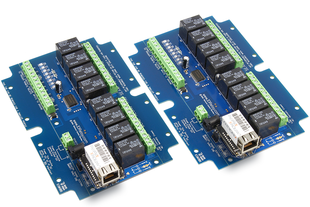
  1. MirX Controllers are equipped with 1, 2, 4, or 8 Relay Outputs. Relays are simply switches. They DO NOT provide a voltage output, but they will switch the voltage you apply to the relay connections. Please Click Here to see a list of relays and ratings that are commonly supported by the NCD product line (note: not all relays may be supported at this time, relay support will grow as the MirX product line grows).
  2. Status LEDs indicate which relays are currently active.
  3. Inputs are capable of reading switches, buttons and other contact closure devices such as many motion detectors.. These input serve as the command points for the remote MirX controller.
  4. MirX Controllers include a 2.1mm Barrel Connector AND a 2-Position Screw Terminal. Use either connector to provide 12V power to the MirX Controller. MirX controllers are compatible with 12V AC or DC power supplies with a actual voltage output of 11 to 13.8V. Polarity is corrected by the MirX controller, therefore a Positive and Negative terminal are NOT labeled on the board (it is not possible to connect power backwards to MirX controllers, the MirX controllers will automatically correct polarity).
  5. Beacon/Smart Mode Jumper is used to switch the controllers from Beacon Mode (good for range testing) to Smart Mode (recommended for day to day function)
  6. The BUSY/READY LEDs indicate CPU activity. Flashing Busy LED signifies VALID data has been received from the Remote MirX controller. If busy light never flashes check remote device and range abilities of devices. G. Communication Device.

Break-Away Tabs

Physically, most MirX controllers are actually two sizes. When you receive your MirX, the shape and size ensures the MirX can fit into a standard enclosure. Optionally, you can make the controller smaller by breaking away the outer tabs. Break-Away tabs are useful in applications where space may be a concern. This allows your MirX to offer the same functionality in the smallest possible profile. Break-Away tabs are unique to the NCD product line and are a standard option for most devices released in 2010 and later.

Before breaking the tabs on your controller, please be advised that your MirX controller will not be returnable for refund or credit if the Break-Away Tabs have been removed.

To break away the tabs, gently but firmly grab each break-away tab with a pair of pliers and bend the tab back and forth until it breaks away from the main circuit board. This will NOT damage the controller in any way.

Breaking the Tabs from a controller DOES NOT VOID the warranty. Please see the NCD return policy if you would like more information on the policies that apply to Surface Mount devices.

MirXR85 is shown above as shipped from National Control Devices. The shape accommodates a standard enclosure. Bend the tabs to break them away from the board. Note that controllers with Broken Tabs are NOT Returnable for Refund or Credit, but are still covered under our 5-Year Limited Warranty

Understanding Inputs

Inputs are capable of reading Contact Closure generating devices such as buttons and switches. A wire connected from the ground terminal to the input terminal would trigger the input, as this would be considered a contact closure.

Warning

Users must NEVER apply any voltage to an input on the MirX controller; these inputs are for Contact Closure connection only.

MirX Inputs play a vital role in the use of a MirX controller. Before we begin using the controller, it is essential that users understand the role of these inputs. Improper use of these inputs can cause Irreparable Damage to the MirX controller, so a firm understanding of these inputs is critical to the longevity of the controller.

A MirX controller has as many inputs as it has relays. So a pair of 2 relay MirX controllers will each have 2 relays and 2 inputs which are used for controlling the relays on the opposite board, the same holds true for 1, 4, and 8 relay versions.

Beacon/Smart Mode Jumper

The Beacon/Smart Mode Jumper is used to change the way communications is handled by the MirX controllers.

Beacon Mode

In Beacon Mode communication is nearly constant. The busy light flashes constantly if there is good communication between the two MirX controllers. If the busy light stops flashing on an Ethernet Pair, connection to the server has been lost. Beacon Mode lengthens the amount of time it takes for an input on one board to trigger a relay on the remote board. Beacon mode is not recommended for day to day use.

Smart Mode

In Smart mode communication is not as constant as in Beacon Mode; however, Smart Mode does still check for communication with remote device periodically. For this reason, inputs on one MirX controller can trigger relays on the remote MirX controller very fast because input changes are immediately sent to the remote device. Smart mode also consumes less power than Beacon mode; this along with fast relay triggering is why we recommend Smart mode for everyday use.

Regardless of the Mode you choose, if the busy LED flashes, the two devices are communicating properly. If the Busy LED does not flash at all, the devices are unable to communicate.

Beacon vs. Smart Mode Comparison
  • Constant communication
  • Good for range testing
  • Higher power consumption
  • Relay Status will update slower to input changes on remote board
  • Fewer communication between devices
  • Lower Power consumption than Beacon mode
  • Relays status updates very fast to input changes on remote board

Understanding Relays

On the previous page, we introduced the MirX Inputs and how Contact Closures play a key role in triggering Relays on the Remote MirX board. In this section we will continue our focus on the hardware portion of the MirX controller, which brings us to our next topic: Understanding how the relays work.

MirX Controllers have 1, 2, 4, or 8 Relays integrated into the circuit board. A relay is similar to a switch. The only difference between a switch and a relay is the actual mechanism for changing the on/off status of the switch. On a switch, you manually push on a piece of metal or plastic to operate the switch. On a relay, an electric current is used to operate the switch. Though a relay resembles the characteristics of a switch, it cannot be controlled by touching it with your finger. So from now on, we will use the word “relay” to indicate a switch that is controlled by the MirX controllers.

Relays do NOT provide a voltage output. They provide a contact closure output, exactly like the terminals found on a light switch at your local hardware store. Wiring to a relay will be slightly different depending on the model of MirX controllers you choose.

Some relays, such as the 5A and 10A versions have screw terminals that can accept 12 Gauge or smaller wire. Other versions such as the 20A and 30A relays have a .250” Quick Connect terminals (the appropriate mating connector can be found at any hardware or automotive supply store).

Again, relays do not provide a voltage output. They ONLY switch whatever voltage you supply into the relay.

Relays are available in SPST, SPDT, and DPDT configurations. In addition, both Mechanical and Solid State relays will be supported by the MirX series controllers. If you are unfamiliar with the different versions of relays available, you can review the article at this link, which explains these relay types in great detail.

The above article will help you determine the best type of relay for your application, showing you the formulas for calculating relays sizes that are appropriate for your application.

If you intend to use the MirX series relay controllers for inductive applications, the article found here MUST be reviewed. An example of an inductive application is any device that involves motion. For instance, using a MirX Controller to control a motor, a solenoid, or a valve. Other types of inductive applications include anything with a transformer such as a fluorescent light or a power transformer of any kind. Logic circuits (including those found on the MirX Controller) may malfunction in severe conditions. The above article will show you how to safely implement these kinds of loads which greatly reduces the chances of a malfunction. Some inductive applications generate excessive noise, and may not be suitable for use with the MirX Series Relay controllers. Solid State MirX Relay Controllers should be considered for these high-noise applications.

Controlling Relays

There is only one way to control the relays on MirX Series controllers. Relays are triggered by inputs on the opposite board. They may not be triggered in any other way. Relay Logic may be used to complete more complex tasks. Please refer to our page on Relay Logic.

Wiring Relays
Relays have 2, 3, or 6 connections per relay depending on configuration. SPST, SPDT, and DPDT relays will be supported. Please see the article at this link for a detailed explanation of these relay types.

Relay Logic

This section will explain why we recommend using MirX controllers with more relays than you may actually need.

Using Relays to Create Logical Conditions
The MirX Series Relay Controllers offer a great balance of flexibility and easy configuration. However, complex decision making is sometimes outside the scope of a MirX controller. Relay Logic demonstrates easy ways to hard-wire your decisions using a MirX Controller.
Sample 1
This sample demonstrates how a relay can be used to activate a light bulb. When the relay turns on, the light comes on. Only one power wire is switched with this sample using the COM (common) and NO (normally open) connections of a relay.
Sample 2
This sample demonstrates how a relay can be used to turn a light bulb OFF. When the relay turns off, the light will be ON. Only one power wire is switched in this sample using the COM (common) and NC (normally closed) connections of a relay
Sample 3
This sample demonstrates how two activated relays are required to activate a light bulb. This is the same as a Logic AND function because Relay 1 AND Relay 2 MUST be on to activate the light.
Sample 4
This sample demonstrates how three activated lights are required to activate a light bulb. This is the same as a Logic AND function because Relay 1 AND Relay 2 AND Relay 3 MUST be on to activate the light
Sample 5
This sample demonstrates the AND/OR function. The Light Bulb will be activated if Relay 1 AND Relay 2 are ON OR if Relay 3 is ON. This sample is perfect for applications that may require a Logical condition of 2 relays PLUS an Override feature. For instance: Relay 1 is a Night/Day Sensor, Relay 2 is a Moisture Sensor. If its dark AND the soil is dry, Relays 1 and 2 can activate a pump. If you want to override these conditions with a Key Fob, Relay 3 may be used.
Sample 6
This sample demonstrates how either relay can be used to activate a light. In this sample, only one activated relay is required to activate the light. If both relays are activated, the light will be on.
Sample 7
This sample demonstrates how a 3-way light switch can be used to activate a light. A 3-way light switch is often found in your house where two light switches can be used to activate a single light. This sample is exactly the same as a 3-way light switch, the only difference being each physical switch is replaced by a relay. Operationally, it works the same way. Each relay activation will cause the light to toggle. Switching two relays at one time is like flipping two switches at once….with the same result. This sample is particularly useful since you can replace one relay (as shown in the diagram) with a physical light switch. This will allow a computer/MirX to control a light as well as manual operation of a light. Properly used, this can be one of the most valuable diagrams we offer
Sample 8
This sample demonstrates how to control the direction of a DC motor using 2 relays. Braking is accomplished by connecting both motor terminals to a common power connection (Faraday’s Law). The capacitors shown may not be required for small motors, but if you experience problems with relays shutting themselves off, the induction suppression capacitor will be required. The .1uF capacitor helps suppress electronic noise if the battery were to be used by sensitive devices (such as radios/amplifiers).

MirX Ethernet

How Ethernet Mirror Modules Work

All Ethernet Mirror Modules work in pairs. Triggering the contact closure input on one board will turn on the relays on the remote board. The local relay status and remote relay status will be indicated on the board through LEDs. The Ethernet Mirror Modules will work on a local area network as well as across Internet. There are redundant communication channels between the two boards, as long as one of them is able to make connection, the boards will work.

Jumper Settings

Beacon Mode Setting

Forces ethernet module into DHCP mode. Useful if incorrect static IP address information is stored in the module.

Smart Mode Setting

In this mode the module will use Static IP address information if set by the user.  DHCP will be used if the user has not specified static IP address information.

Connection Options—Default Settings

In this mode the module will use Static IP address information if set by the user.  DHCP will be used if the user has not specified static IP address information.

Option 1 - Connect Directly

When two modules are in the same local area network, they can communicate to each other directly without a Mirror Server. No Internet connection is required.

Option 2 - Connection through Internet with NCD Mirror Server

When two mirror modules are located in different networks, they can talk to each other through the NCD Mirror Server. Mirror modules can connect to up to four servers at the same time. As long as one of the servers can be connected to, the mirror modules will work.

Quick Setup for Direct Connection (no Internet required)

Equipment Required:

  • A Router supporting DHCP
  • Two mirror modules connected to the same router.

Steps:

  • Connect the two Mirror modules that need to be paired to the LAN through router.
  • Connect 12vDC power source.

The two modules can communicate with each other directly over a LAN through this quick setup.

Quick Setup for Internet Connection

Equipment Required:

  • A Router at each location with Internet Connection that support DHCP.
  • Two mirror modules connected to each router.

Steps:

  • Connect the two Mirror modules that need to be paired to the LAN through router.
  • Connect 12vDC power source.

The two modules can communicate with each other directly over an Internet Connection utilizing NCD maintained Signal Switch server through this quick setup.

MirX Ethernet Configuration

NCD Base Station Software

The devices have been paired by NCD prior to shipment and require no configuration; however, if you wish to make changes in this pairing, you may use the NCD Base Station software to change the configuration settings. This can also be a valuable troubleshooting tool because of its ability to show devices that are communicating on your network.

Steps to View/Pair Devices
  • From the Base Station ‘Select Connection’ opening window, click on ‘MXNET/MCNET Device Pairing Utility’.
    • Select MXNET/MCNET Device Pairing Utility
  • Select both devices in list and click the “Pair with Factory Setting” button to use the NCD mirror server. The connected symbols should show in front of the item once they are paired.
  • Select both devices in list and click the “Pair” button to pair two devices. The connected symbols should show in front of the item once they are paired. Note: The server setting will not change.

Mirror Server Setup

Setting up your own Mirror Server

The following instructions are given for those users who prefer to set up their own mirror server. Prior network and Windows Service knowledge is required of the user before attempting to set up their own mirror service.

The software installed on our Signal Switch server which operates the Ethernet MirX controllers can be downloaded HERE. The controllers may be configured to connect with up to 4 servers providing communication backup in case a server goes offline. The NCD Base Station software will be required for configuring controllers to use your own server. This software also allows you to pair controllers together and change the Master/Slave parameters. There must be one master controller and one Slave controller.

A Mirror Server is a program that forwards messages between matched devices. Setup the Mirror Server on Microsoft Windows platform.

The Mirror Server can run as a windows console program or run as a windows service.

Option 1 - Run Mirror Server as a Console Program

Quick Setup

  • Double click the MirrorServer.exe.
  • A console window will be opened.

Note: Firewall setting. The program has to be allowed in Windows Firewall setting

Option 2 - Run Mirror Server as a Service

Run “ServerManager.exe”The service needs to be installed first.

  • Click “Install Mirror Server Service” to install the service to the computer.
  • Click “Start” button to start the service.

The Server Manager needs to be run as Administrator. Firewall setting is required to run this program. NCDMirrorServerSvr.exe needs to be added to exception of the Windows firewall.

Suggestion:

It is strongly suggested to run console version server first to make sure everything is working before running as a service.

The advantage of running as a service is that the program will run in background and will be started automatically when the windows starts.

Advanced Configuration

Advanced Setup
Equipment Required
  • A Router at each location
  • A computer connected to Internet
  • Two mirror modules connected to a router
Steps
  • Connect the two Mirror modules that need to be paired to a router at their location.
  • Run NCD Base Station software on computer connected to the Internet.
  • Select one module and click the “Edit” button.
  • Input the server address and port number. The default port is 8005. Both modules need to be edited. Input 0.0.0.0 if there is no server. For example, if only one server is used, input 0.0.0.0 for the rest of the servers. The remote Mac address can be setup in the next steps.
  • Select the two modules in the list and click “Pair”
  • Once the two modules are paired, a connected symbol will show in front of the items.

The pair setup with servers can work through Internet. It is not necessary to be in same local network.

Tips

Set the Remote Mac Address same as Local Mac Address. This can be used to test the device connection with the server. When the remote address is the same as the local address, it will loop back when an input is triggered, triggering a relay on the same board.

Electrical Specifications

 MaximumRatedMinimum
Temperature Ratings (Estimated)**-25°C 80°C
    
Mechanical Relay Cycle Life (Non-DPDT Versions): >10,000,000 Cycles 
Mechanical Relay Cycle Life (DPDT Versions): >2,000,000 Cycles 
Typical Operational Cycles per Minute  1,800
Relay Activation Time:>5ms <15ms
Relay Deactivation Time:>5ms <20ms
Command Processing Time:1ms3ms5ms

Relay Electrical Limits should be Determined by Reviewing Appropriate Relay Data Sheet

** Ratings Based on Data Sheets of Component Used, Actual Tolerance May Exceed Ratings.

Troubleshooting

Set the Remote Mac Address same as Local Mac Address. This can be used to test the device connection with the server. When the remote address is the same as the local address, it will loop back when an input is triggered, triggering a relay on the same board.

Busy LED does not Flash

  • Check all power connections and Ethernet connections at both locations.
  • Check Internet connection at both locations.
  • Make sure Ethernet MirX controllers have network or Internet connection by running the Pairing Utility. If the controllers appear on the utility, they have Local Area Network Connection. If they do not, they are denied access. This can be caused by firewall and password protection.
  • If connection cannot be established, bring both controllers to one location and attach them to the same LAN. Run the Pairing Utility and attempt to pair them together

Controller is Running HOT

It is normal for some components run very hot on the MirX series relay controllers. This is not a concern as we have tested the design carefully and are operating our components well within the specified limits of the components we are using. It is NOT normal for the CPU to run hot at any time. The CPU should remain cool. If the CPU is running hot the CPU has been damaged.

Relays Turn Off Unexpectedly

This can happen if the devices lose communication with each other in Smart mode. It can also happen when Inductive loads are attached to the relays (See Understanding Relays).

  • Shorten the distance between controllers.
  • Carefully review the necessary steps for suppressing Induction in this Article.
  • Be sure to also check your power source.