| Frame Field | Offset (Payload Section) | Fixed Value
(if any) | Description |
|---|
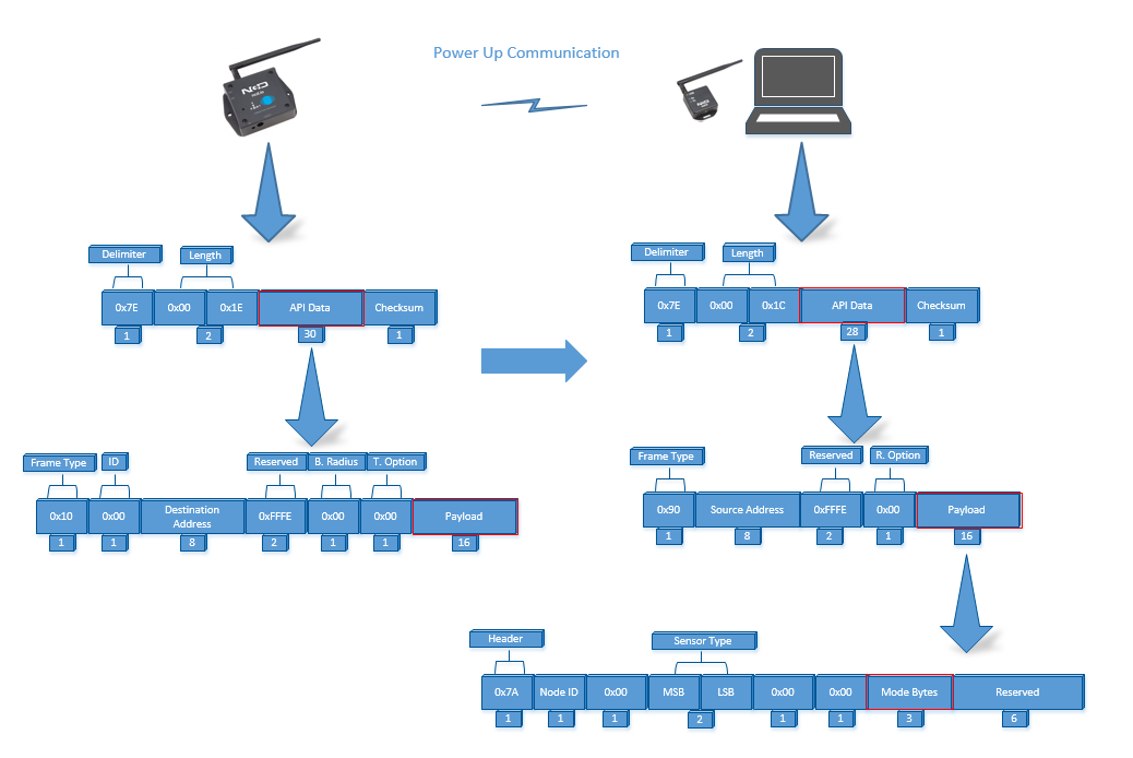
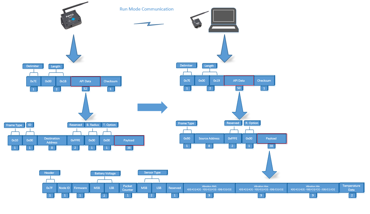
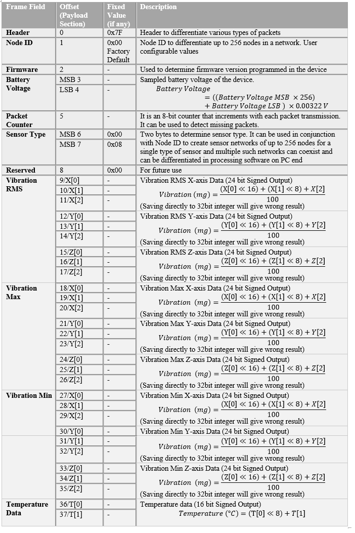
| Header | 0 | 0x7F | | Header to differentiate various type of packets |
|
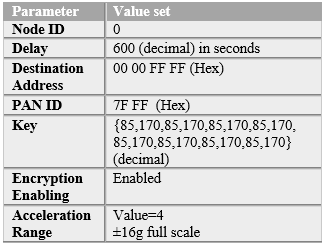
| Node ID | 1 | 0x00 Factory Default | | Node ID to differentiate up to 256 nodes in a network. User configural values |
|
|
| Firmware | 2 | – | | Used to determine firmware version programmed in the device |
|
|
| Battery Voltage | MSB 3 | – | Sampled battery voltage of the device. Battery Voltage=((Battery Voltage MSB x 256+Battery Voltage LSB) x 0.00322 V |
| LSB 4 | – |
| Packet Counter | 5 | – | | It is an 8-bit counter that increments with each packet transmission. It can be used to detect missing packets. |
|
|
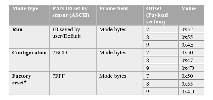
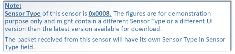
| Sensor Type | MSB 6 | 0x00 | | Two bytes to determine sensor type. It can be used in conjunction with Node ID to create sensor networks of up to 256 nodes for a single type of sensor and multiple such networks can coexist and can be differentiated in processing software on PC end |
|
|
| MSB 7 | 0x08 |
| Reserved | 8 | 0x00 | |
| Vibration RMS | 9/X[0] | – | Vibration RMS X-axis Data (24 bit Signed Output) Vibration (mg) = ((X[0]<<16)+(X[1]<<8)+X[2])/100 (Saving directly to 32 bit integer will give wrong result |
| 10/X[1] | – |
| 11/X[2] | – |
| 12/Y[0] | – | Vibration RMS Y-axis Data (24 bit Signed Output) Vibration (mg) = ((Y[0]<<16)+(Y[1]<<8)+Y[2])/100 (Saving directly to 32 bit integer will give wrong result |
| 13/Y[1] | – |
| 14/Y[2] | – |
| 15/Z[0] | – | Vibration RMS Z-axis Data (24 bit Signed Output) Vibration (mg) = ((Z[0]<<16)+(Z[1]<<8)+Z[2])/100 (Saving directly to 32 bit integer will give wrong result |
| 16/Z[1] | – |
| 17/Z[2] | – |
| Vibration Max | 18/X[0] | – | Vibration Max X-axis Data (24 bit Signed Output) Vibration (mg) = ((X[0]<<16)+(X[1]<<8)+X[2])/100 (Saving directly to 32 bit integer will give wrong result |
| 19/X[1] | – |
| 20/X[2] | – |
| 21/Y[0] | – | Vibration Max Y-axis Data (24 bit Signed Output) Vibration (mg) = ((Y[0]<<16)+(Y[1]<<8)+Y[2])/100 (Saving directly to 32 bit integer will give wrong result |
| 22/Y[1] | – |
| 23/Y[2] | – |
| 24/Z[0] | – | Vibration Max Z-axis Data (24 bit Signed Output) Vibration (mg) = ((Z[0]<<16)+(Z[1]<<8)+Z[2])/100 (Saving directly to 32 bit integer will give wrong result |
| 25/Z[1] | – |
| 26/Z[2] | – |
| Vibration Min | 27/X[0] | – | Vibration Min X-axis Data (24 bit Signed Output) Vibration (mg) = ((X[0]<<16)+(X[1]<<8)+X[2])/100 (Saving directly to 32 bit integer will give wrong result |
| 28/X[1] | – |
| 29/X[2] | – |
| 30/Y[0] | – | Vibration Min Y-axis Data (24 bit Signed Output) Vibration (mg) = ((Y[0]<<16)+(Y[1]<<8)+Y[2])/100 (Saving directly to 32 bit integer will give wrong result |
| 31/Y[1] | – |
| 32/Y[2] | – |
| 33/Z[0] | – | Vibration Min Z-axis Data (24 bit Signed Output) Vibration (mg) = ((Z[0]<<16)+(Z[1]<<8)+Z[2])/100 (Saving directly to 32 bit integer will give wrong result |
| 34/Z[1] | – |
| 35/Z[2] | – |
| Temperature Data | 36/T[0] | – | Temperature data (16 bit Signed Output) Temperature (°C) = (T[0]<<8)+T[1] |
| 37/T[1] | – |