Introduction
1
- Industrial Grade 3-axis Vibration Sensor with ±16g Range
- Calculates RMS, MAX, and MIN g Vibration
- Noise Removal using Low-pass Filter
- Frequency Range (Bandwidth) up to 6400 Hz In Processed Mode
- Frequency Range (Bandwidth) up to 8,000 Hz In Time Domain Mode
- Sample Rate up to 25,600Hz
- Time Domain Data for FFT analysis
- Encrypted Communication with 2 Mile Wireless Range
- Operating Temperature Range -40 to +60 °C
- Humidity Range 0-90%
- Wall-Mounted or Magnet Mounted IP65 Rated Enclosure
- For Indoor and Outdoor Use
- Example Software for Visual Studio and LabVIEW
- Vibration Sensor with External Probe Option
- Up to 500,000 Transmissions from 4 AA Batteries
- Many Gateway and Modem Options Available
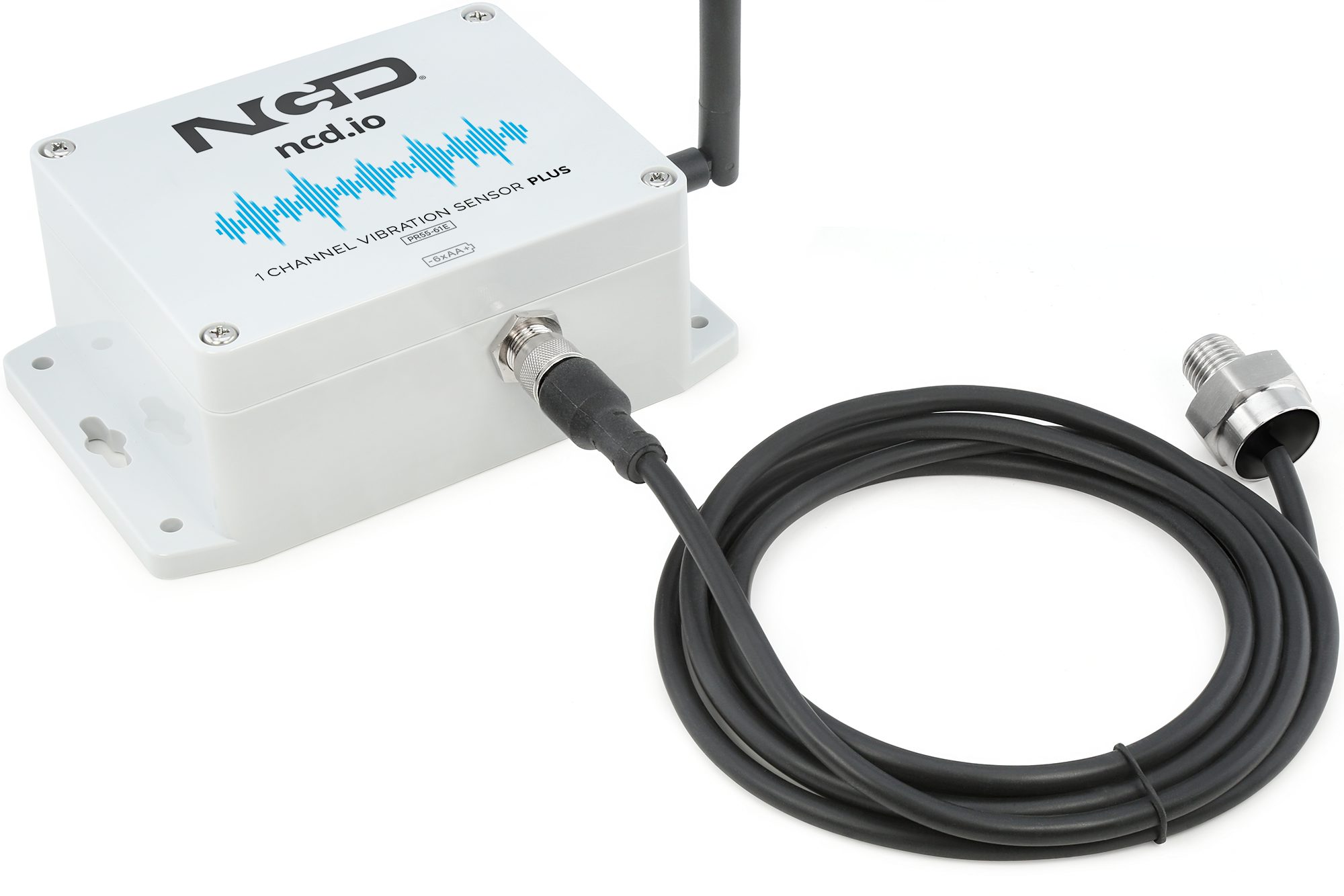
Introducing NCD’s Long Range Industrial IoT wireless vibration and temperature sensor, boasting up to a 2 Mile range using a wireless mesh networking architecture. Incorporating a 16-bit Vibration and Temperature sensor, this sensor transmits highly accurate vibration data at user-defined intervals.
During Power-Up, this vibration sensor learns “normal” base-line vibration from the monitored device. This base-line vibration is subtracted from regular sampled vibration readings to improve relevant vibration data. Ideally, the monitored device should be off while the sensor is learning. Once the sensor stabilizes and starts sending data, the device/machinery being monitored can be powered on.
This Industrial IoT wireless vibration sensor samples 3-axis of Vibration data for 900ms and then calculates RMS, Maximum, and Minimum vibration readings. This sensor combines these data with temperature data in a data packet, and transmits the result to modems and gateways within wireless range. Once transmission is complete, the vibration sensor goes back to sleep, thus minimizing power consumption.
Powered by just 6 AA batteries and an operational lifetime of 500,000 wireless transmissions, a 10 years battery life can be expected depending on environmental conditions and the data transmission interval. Optionally, this sensor may be externally powered, making it an ideal choice for wireless vibration monitoring system for industrial equipment.
With an open communication protocol, this sensor transmits hardware encrypted data that can be integrated with just about any control system or gateway. Data can be transmitted to a PC, a Raspberry Pi, to Losant IoT cloud, Microsoft® Azure® IoT, and an embedded system all at the same time. Sensor parameters and wireless transmission settings can be changed using our free LabVIEW® monitoring software on a desktop PC.
The long range, price, accuracy, battery life and security features of Wireless Vibration Sensor makes it an affordable choice which exceeds the requirements for most of the industrial as well as consumer market applications.
Specifications
| Specifications | Minimum | Nominal | Maximum | Notes |
|---|---|---|---|---|
| Transmission Rating | 500,000 | Total Number of Wireless Transmissions When Using 4 AA Batteries | ||
| Batteries | 2 | 6 | 6 | May be Powered by 2 or 4 AA Batteries |
| Battery Life 1 TPD | 10 Years | TPD Transmissions per Day | ||
| Battery Life 3 TPD | 8 Years | TPD Transmissions per Day | ||
| Battery Life 6 TPD | 4 Years | TPD Transmissions per Day | ||
| Battery Life 12 TPD | 2 Years | TPD Transmissions per Day | ||
| Battery Life 24 TPD | 1 Year | TPD Transmissions per Day | ||
| Width | 3.54" | |||
| Length | 4.52" | |||
| Height | 2.16" | |||
| Enclosure Rating | IP65, NEMA 1,2,4,4X,12,13, UL-508 | |||
| Temperature Rating | -40° C | 23° C | 85° C | Component Rating |
| Tested Temperature | 0° C | 23° C | 40° C | As Tested by NCD Staff |
| Probe Temperature | -40° C | 23° C | 105° C | As Tested by NCD Staff |
| X Vibration Range | -16g | +16g | ||
| Y Vibration Range | -16g | +16g | ||
| Z Vibration Range | -16g | +16g | ||
| X Velocity Range | 0-655mm/sec | |||
| Y Velocity Range | 0-655mm/sec | |||
| Z Velocity Range | 0-655mm/sec | |||
| X Displacement Range | 0-655mm | |||
| Y Displacement Range | 0-655mm | |||
| Y Displacement Range | 0-655mm | |||
| Sample Rate | 100hz | 1600hz | 12.8Khz | Vibration Sensor Data Rate |
| Frequency Range ( Processed Mode) | 1.56hz | 400hz | 3200hz | Freq range should be equal or greater than machine RPM |
| Frequency Range ( Time Domain Mode) | 0.56hz | 800hz | 8,000hz | |
| Sample Duration | 1sec | 1sec | 10sec | Device will take readings for the set time and then send over wireless |
| Time Domain Data | Yes | |||
| Filters | Yes | |||
| Mounting | 1/4 NPT 1/4-28 UNF Magnet Mount | |||
| FFT | Yes |
Use Energizer Ultimate Lithium ONLY for Extreme Temperatures
All Ratings are for 6 Batteries
Actual Battery Life is Dependent On Transmission Interval
Battery Shelf Life Does Not Exceed 10 Years Therefore NCD Does Not Rate Battery Life Beyond the Shelf Life of Available Batteries
** Battery life will significantly reduce when time domain mode is enabled
Applications
3
- Wireless Industrial Machine Health Analysis
- Machine Fault detection
- Frequency Analysis of Vibration data
- Building and Structural Monitoring
Hardware
4
Sensor Hardware
The vibration Sensor hardware can be divided into two parts.
A. Main Electronics Box — This box ( White Box) contains Electronics such as MCU, Radio Module, Power Circuitry, Power Control unit, Status LED, on/off Switch, Configuration Button etc.

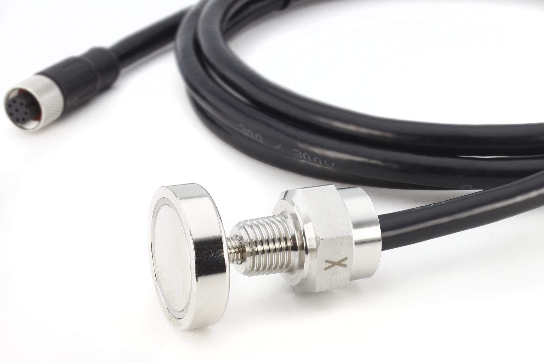
B. The Probe — The probe is made of steel. It contain the Vibration sensor and the temperature Sensor. It comes with 3 mounting option such as 1/4 NPT, 1/4-28 UNF and magnetic Mount. The sensor cable length is 2meter and its shielded twisted pair wire cable.


Sensor Diagram
Temperature Sensor
The NCD V3 Vibration Sensor also includes a integrated temperature sensor. This temperature sensor serves two functions. First, this sensor is used to keep the integrated vibration sensor accurate over the operating temperature range. Second, this sensor may be used to monitor the temperature of machinery in select circumstances. Please keep in mind the integrated sensor is epoxy filled and the sensor must be saturated with heat (heat soaked) before the temperature measurements will be accurate for machine measurement. The time delay for heat transfer will greatly depend on the operating environment and machine attachment location. For machine temperature measurement applications, the magnetic attachment should not be used as it provides too great of a thermal insulator. For best results, thermal conductive compound should be used for faster temperature transfer to the sensor probe using the threaded fittings. This probe should not be used for temperature measurement applications if you require instantaneous machine temperature readings, a separate dedicated sensor probe is required for these applications (such as a thermocouple).
Sensor Power
This Sensor has two power options.
- Powered by AA batteries ( NCD recommends Energizer L91 batteries)
- External Power Supply ( 5-12VDC) Current Requirement 250mA
The L91 Batteries are non-rechargeable Li-Ion batteries.
While changing the batteries
- Turn off The sensor
- Only use new L91 batteries
- Checkout the Polarity marking on the Battery Holder and Batteries
- Replace All six batteries with new L91 batteries. Do not mix old and new batteries
- Batteries should not be replaced in fire risky areas
- Do NOT install rechargeable batteries
Sensor Radio Technology
NCD Long Range Wireless Sensors are available with many radio options, which should be carefully chosen based on the country of installation. NCD uses Digi radios exclusively because of their best-in-class range, reliability, wide operating temperature, and low power operation. Please note that not all options are legal for use in all areas, so it’s important to make the right selection during purchase. NCD manufactures sensors based on the radio options chosen, we do not typically restrict radios to certain countries so please check local laws BEFORE purchase. Here, we will explain the radio options in greater detail to help guide users into the correct radio based on installation country.
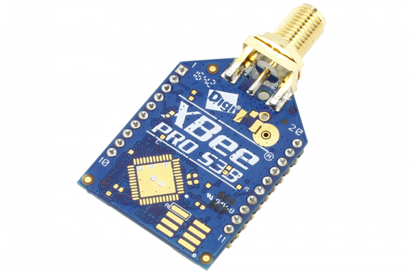
900MHz for Use in the United States
If NCD sensors will be installed within the United States, the 900MHz (North America) option is the best choice, offering the longest possible range of up to 2 Miles Line of Sight and up to 28 Miles using High-Gain Antennas. This option can typically work up to 1,000 feet indoors (depending on building materials, concrete and steel building typically reduce the operational range significantly). This option is typically not legal for use outside North America.
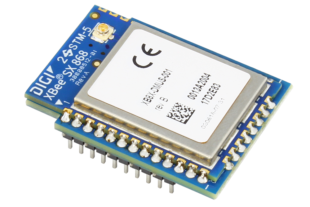
868MHz for Use in Europe
If NCD sensors will be installed in Europe, the 868MHz (Europe Only) option is the best choice, offering the longest possible range of up to 14.5km Line of Sight. This option is typically not legal for use outside of Europe.
2.4GHz for Worldwide Use
The 2.4GHz Option is generally legal for use in most countries, including Europe and the United States and offers a range of up to 2 Miles (3200 Meters) Line of Sight or up to 300 feet (about 90 Meters) indoors. Because of the widespread use of 2.4GHz, the rated ranges are rarely achieved. The 900MHz and 868MHz communication modules are a far better choice for users in the United States and Europe respectively. Users who may require worldwide compliance should use the 2.4GHz option, but this option should be considered if the above options are not legal for use.
Sensor Internal Overview
The Vibration Sensor V3 has two Key components.
A. Main Sensor Body – The main sensor Body contains MCU, Power Supply, Radio module, Status LED, Batteries, power on/off Switch and other electronics.
B. Sensor Probe – The probe is made of stainless steel. Inside the probe there is a Vibration sensor and Temperature Sensor. The probe Length is around 2meter. The probe can be mounted using a Magnetic attachment, 1/4-28 UNF, and 1/4 NPT.

Status LED – The status led is used to indicate errors or other sensor diagnostics.
LED Blink Once – Message was sent successfully and no error in last sensor read as well in data transmission
LED Blink Twice and then One more time — Message was sent successfully but there was an error in last sensor read
LED blink Thrice — MCU is having issue communicating with Radio Module
Software API Structure
6
Sensor Transmission Structure RAW Mode
| Field | Description | Comment |
|---|---|---|
| Header | 7F | API Data Header ( its not the API Header) |
| Node ID | 00 | User Defined ID |
| Firmware Version | 01 | Device Firmware Version |
| Battery Level | 03,FE | Battery Voltage = 0.00322*(03*FF+FE) |
| Packet Counter | DE | Wireless Transmission Counter |
| Sensor Type | 00,0x51 | Sensor Type 80 |
| Error/Reserve Byte | 00 | |
| 01 | Mode Of Operation | |
| 0A | ODR | |
| 07 | Three MSB bit of the Axis byte to indicate FSR And 3 LSB bits indicates Axis | |
| 13 | Hour | |
| 0B | Minute | |
| 00,00 | Device Temperature | |
| 77 | Total Number of RF Packets | |
| 01 | Current Packet Count value | |
| 01 DE | X1-Axis RAW ACC Data | X1= (01*0xFF+ 0xDE)*FSR coefficient |
| FF 7A | Y1-Axis RAW ACC Data | Y1= (01*0xFF+ 0x7A)*FSR coefficient |
| 3F 8B | Z1-Axis RAW ACC Data | Z1= (01*0x3F+ 0x8B)*FSR coefficient |
| 01 DF | X2-Axis RAW ACC Data | X1= (01*0xFF+ 0xDF)*FSR coefficient |
| FF 7B | Y2-Axis RAW ACC Data | Y2= (01*0xFF+ 0x7B)*FSR coefficient |
| 3F 8C | Z2-Axis RAW ACC Data | Z2= (01*0x3F+ 0x8C)*FSR coefficient |
FSR Coefficient Values
FSR is 2g — 0.00006
FSR is 4g — 0.00012
FSR is 8g — 0.00024
FSR is 16g — 0.00049
Data Spacing
The functionality of this sensor is based on the utilization of a node id to distribute the raw data. It is important to note that the data spacing is only applicable in the Raw and Raw on-request modes. The duration of data spacing is as follows:
Processed + Raw on-request mode – 5 seconds
Raw mode – 20 seconds
Let’s consider an example scenario where Sensor A has a node id of 10. It transmits processed data packets and users request raw data. The sensor receives the command, computes the raw data, and goes back to sleep for (node id * 5 seconds) before sending the raw data. In this specific case, the sensor will return to sleep for 50 seconds and then transmit the raw data.
The rationale behind implementing this feature is that in a network with multiple sensors, each sensor will receive a fair share of airtime to transmit raw data.
NOTE – If this sensor is being used with 2.4ghz, make sure the payload length is set to 55 bytes.
Enter Configuration Mode
Sensor Type 80 Processed Data Payload Structure
| Field | Value ( or Default ) | Payload | Length | Description |
|---|---|---|---|---|
| Header | 7F | 1 | API Data Header ( its not the API Header) | |
| Node ID | 00 | 1 | User Defined ID | |
| Firmware Version | 01 | 1 | Device Firmware Version |
|
| Battery Level | 03,FE | 2 | Battery Voltage = 0.00322*(03*FF+FE) | |
| Packet Counter | DE | 1 | Wireless Transmission Counter |
|
| Sensor Type | 00,0x51 | 2 | Sensor Type 80 | |
| Error/Reserve Byte | 00 | 1 | bit 0: OTF Ready (Ignored in this app as we do not depend on the common code for OTF) bit 1: (Validity of Data for sensor 1 , 0 means data is valid, 1 means error in accessing sensor) bit 2: (Validity of Data for sensor 2 , 0 means data is valid, 1 means error in accessing sensor) bit 3: Sensor 2 indicator bit (only in dual probe) , if this bit is set it means the packet has data for sensor 2. In Raw mode/Raw on Rqst, this bit is set only when raw data is coming from sensor 2, if not , then it is coming from sensor 1 In Processed mode, this bit is set to indicate that the packet includes data from sensor 1 and 2 bit 4 - 7 : Unused |
|
| Mode Of Operation | 00 | 0 | 1 | 00- Processed 01- Raw 02 - On Demand |
| Data Rate | 0A | 1 | 1 | Vibration Sample Rate |
| Temperature | MSB,LSB | 2,3 | 2 | Temp in C = (MSB*FF+LSB)/100 |
| RMS ACC in X Axis in mg | MSB,LSB | 4,5 | 2 | rms_acc_x_mg = MSB*FF+LSB |
| MAX ACC in X Axis in mg | MSB,LSB | 6,7 | 2 | max_acc_x_mg = MSB*FF+LSB |
| RMS Velocity in X Axis in mm/sec | MSB,LSB | 8,9 | 2 | rms_vel_x_mm_sec = (MSB*FF+LSB)/100 |
| RMS Displacement in X Axis in mm | MSB,LSB | 10,11 | 2 | rms_disp_x_mm = (MSB*FF+LSB)/100 |
| Frequency of Highest Peak in X direction | MSB,LSB | 12,13 | 2 | X1_Hz = (MSB*FF+LSB) |
| Frequency of Second Highest Peak in X direction | MSB,LSB | 14,15 | 2 | X2_Hz = (MSB*FF+LSB) |
| Frequency of Third Highest Peak in X direction | MSB,LSB | 16,17 | 2 | X3_Hz = (MSB*FF+LSB) |
| RMS ACC in Y Axis in mg | MSB,LSB | 18,19 | 2 | rms_acc_y_mg = MSB*FF+LSB |
| MAX ACC in Y Axis in mg | MSB,LSB | 20,21 | 2 | max_acc_y_mg = MSB*FF+LSB |
| RMS Velocity in Y Axis in mm/sec | MSB,LSB | 22,23 | 2 | rms_vel_y_mm_sec = (MSB*FF+LSB)/100 |
| RMS Displacement in Y Axis in mm | MSB,LSB | 24,25 | 2 | rms_disp_y_mm = (MSB*FF+LSB)/100 |
| Frequency of Highest Peak in Y direction | MSB,LSB | 26,27 | 2 | Y1_Hz = (MSB*FF+LSB) |
| Frequency of Second Highest Peak in Y direction | MSB,LSB | 28,29 | 2 | Y2_Hz = (MSB*FF+LSB) |
| Frequency of Third Highest Peak in Y direction | MSB,LSB | 30,31 | 2 | Y3_Hz = (MSB*FF+LSB) |
| RMS ACC in Z Axis in mg | MSB,LSB | 32,33 | 2 | rms_acc_z_mg = MSB*FF+LSB |
| MAX ACC in Z Axis in mg | MSB,LSB | 34,35 | 2 | max_acc_z_mg = MSB*FF+LSB |
| RMS Velocity in Z Axis in mm/sec | MSB,LSB | 36,37 | 2 | rms_vel_z_mm_sec = (MSB*FF+LSB)/100 |
| RMS Displacement in Z Axis in mm | MSB,LSB | 38,39 | 2 | rms_disp_z_mm = (MSB*FF+LSB)/100 |
| Frequency of Highest Peak in Z direction | MSB,LSB | 40,41 | 2 | Z1_Hz = (MSB*FF+LSB) |
| Frequency of Second Highest Peak in Z direction | MSB,LSB | 42,43 | 2 | Z2_Hz = (MSB*FF+LSB) |
| Frequency of Third Highest Peak in Z direction | MSB,LSB | 44,45 | 2 | Z3_Hz = (MSB*FF+LSB) |
Sensor Type 81 Processed Data Payload Structure
| Field | Value ( or Default ) | Length | Description |
|---|---|---|---|
| Header | 7F | 1 | API Data Header ( its not the API Header) |
| Node ID | 00 | 1 | User Defined ID |
| Firmware Version | 01 | 1 | Device Firmware Version |
| Battery Level | 03,FE | 2 | Battery Voltage = 0.00322*(03*FF+FE) |
| Packet Counter | DE | 1 | Wireless Transmission Counter |
| Sensor Type | 00,0x51 | 2 | Sensor Type 80 |
| Error/Reserve Byte | 00 | 1 | |
| Mode Of Operation | 00 | 1 | 00- Processed 01- Raw 02 - On Demand |
| Data Rate | 0A | 1 | Vibration Sample Rate |
| Temperature Sensor 1 | MSB,LSB | 2 | Temp in C = MSB*FF+LSB |
| RMS ACC in X Axis in mg | MSB,LSB | 2 | rms_acc_x_mg = MSB*FF+LSB |
| MAX ACC in X Axis in mg | MSB,LSB | 2 | max_acc_x_mg = MSB*FF+LSB |
| RMS Velocity in X Axis in mm/sec | MSB,LSB | 2 | rms_vel_x_mm_sec = (MSB*FF+LSB)/100 |
| RMS Displacement in X Axis in mm | MSB,LSB | 2 | rms_disp_x_mm = (MSB*FF+LSB)/100 |
| Frequency of First Peak in X direction | MSB,LSB | 2 | X1_Hz = (MSB*FF+LSB) |
| Frequency of Second Peak in X direction | MSB,LSB | 2 | X2_Hz = (MSB*FF+LSB) |
| Frequency of Third Peak in X direction | MSB,LSB | 2 | X3_Hz = (MSB*FF+LSB) |
| RMS ACC in Y Axis in mg | MSB,LSB | 2 | rms_acc_y_mg = MSB*FF+LSB |
| MAX ACC in Y Axis in mg | MSB,LSB | 2 | max_acc_y_mg = MSB*FF+LSB |
| RMS Velocity in Y Axis in mm/sec | MSB,LSB | 2 | rms_vel_y_mm_sec = (MSB*FF+LSB)/100 |
| RMS Displacement in Y Axis in mm | MSB,LSB | 2 | rms_disp_y_mm = (MSB*FF+LSB)/100 |
| Frequency of First Peak in Y direction | MSB,LSB | 2 | Y1_Hz = (MSB*FF+LSB) |
| Frequency of Second Peak in Y direction | MSB,LSB | 2 | Y2_Hz = (MSB*FF+LSB) |
| Frequency of Third Peak in Y direction | MSB,LSB | 2 | Y3_Hz = (MSB*FF+LSB) |
| RMS ACC in Z Axis in mg | MSB,LSB | 2 | rms_acc_z_mg = MSB*FF+LSB |
| MAX ACC in Z Axis in mg | MSB,LSB | 2 | max_acc_z_mg = MSB*FF+LSB |
| RMS Velocity in Z Axis in mm/sec | MSB,LSB | 2 | rms_vel_z_mm_sec = (MSB*FF+LSB)/100 |
| RMS Displacement in Z Axis in mm | MSB,LSB | 2 | rms_disp_z_mm = (MSB*FF+LSB)/100 |
| Frequency of First Peak in Z direction | MSB,LSB | 2 | Z1_Hz = (MSB*FF+LSB) |
| Frequency of Second Peak in Z direction | MSB,LSB | 2 | Z2_Hz = (MSB*FF+LSB) |
| Frequency of Third Peak in Z direction | MSB,LSB | 2 | Z3_Hz = (MSB*FF+LSB) |
| Data Rate Sensor 2 | 0A | 1 | Vibration Sample Rate |
| Temperature Sensor 2 | MSB,LSB | 2 | Temp in C = MSB*FF+LSB |
| RMS ACC in X Axis in mg Sensor 2 | MSB,LSB | 2 | rms_acc_x_mg = MSB*FF+LSB |
| MAX ACC in X Axis in mg Sensor 2 | MSB,LSB | 2 | max_acc_x_mg = MSB*FF+LSB |
| RMS Velocity in X Axis in mm/sec Sensor 2 | MSB,LSB | 2 | rms_vel_x_mm_sec = (MSB*FF+LSB)/100 |
| RMS Displacement in X Axis in mm Sensor 2 | MSB,LSB | 2 | rms_disp_x_mm = (MSB*FF+LSB)/100 |
| Frequency of First Peak in X direction Sensor 2 | MSB,LSB | 2 | X1_Hz = (MSB*FF+LSB) |
| Frequency of Second Peak in X direction Sensor 2 | MSB,LSB | 2 | X2_Hz = (MSB*FF+LSB) |
| Frequency of Third Peak in X direction Sensor 2 | MSB,LSB | 2 | X3_Hz = (MSB*FF+LSB) |
| RMS ACC in Y Axis in mg Sensor 2 | MSB,LSB | 2 | rms_acc_y_mg = MSB*FF+LSB |
| MAX ACC in Y Axis in mg Sensor 2 | MSB,LSB | 2 | max_acc_y_mg = MSB*FF+LSB |
| RMS Velocity in Y Axis in mm/sec Sensor 2 | MSB,LSB | 2 | rms_vel_y_mm_sec = (MSB*FF+LSB)/100 |
| RMS Displacement in Y Axis in mm Sensor 2 | MSB,LSB | 2 | rms_disp_y_mm = (MSB*FF+LSB)/100 |
| Frequency of First Peak in Y direction Sensor 2 | MSB,LSB | 2 | Y1_Hz = (MSB*FF+LSB) |
| Frequency of Second Peak in Y direction Sensor 2 | MSB,LSB | 2 | Y2_Hz = (MSB*FF+LSB) |
| Frequency of Third Peak in Y direction Sensor 2 | MSB,LSB | 2 | Y3_Hz = (MSB*FF+LSB) |
| RMS ACC in Z Axis in mg Sensor 2 | MSB,LSB | 2 | rms_acc_z_mg = MSB*FF+LSB |
| MAX ACC in Z Axis in mg Sensor 2 | MSB,LSB | 2 | max_acc_z_mg = MSB*FF+LSB |
| RMS Velocity in Z Axis in mm/sec Sensor 2 | MSB,LSB | 2 | rms_vel_z_mm_sec = (MSB*FF+LSB)/100 |
| RMS Displacement in Z Axis in mm Sensor 2 | MSB,LSB | 2 | rms_disp_z_mm = (MSB*FF+LSB)/100 |
| Frequency of First Peak in Z direction Sensor 2 | MSB,LSB | 2 | Z1_Hz = (MSB*FF+LSB) |
| Frequency of Second Peak in Z direction Sensor 2 | MSB,LSB | 2 | Z2_Hz = (MSB*FF+LSB) |
| Frequency of Third Peak in Z direction Sensor 2 | MSB,LSB | 2 | Z3_Hz = (MSB*FF+LSB) |
Sensor Type 82 Processed Data Payload Structure
| Field | Value ( or Default ) | Length | Description |
|---|---|---|---|
| Header | 7F | 1 | API Data Header ( its not the API Header) |
| Node ID | 00 | 1 | User Defined ID |
| Firmware Version | 01 | 1 | Device Firmware Version |
| Battery Level | 03,FE | 2 | Battery Voltage = 0.00322*(03*FF+FE) |
| Packet Counter | DE | 1 | Wireless Transmission Counter |
| Sensor Type | 00,0x52 | 2 | Sensor Type 82 |
| Error/Reserve Byte | 00 | 1 | |
| Mode Of Operation | 00 | 1 | 00- Processed 01- Raw 02 - On Demand |
| Data Rate | 0A | 1 | Vibration Sample Rate |
| Temperature Sensor 1 | MSB,LSB | 2 | Temp in C = MSB*FF+LSB/100 |
| Temperature Sensor External | MSB1,MSB,LSB1,LSB | 4 | Temp in C = MSB1<<24+MSB<<16+LSB1<<8+LSB/100 |
| Current Sensor | MSB1,MSB,LSB1,LSB | 4 | Current in Amp = MSB1<<24+MSB<<16+LSB1<<8+LSB/1000 |
| RMS ACC in X Axis in mg | MSB,LSB | 2 | rms_acc_x_mg = MSB*FF+LSB |
| MAX ACC in X Axis in mg | MSB,LSB | 2 | max_acc_x_mg = MSB*FF+LSB |
| RMS Velocity in X Axis in mm/sec | MSB,LSB | 2 | rms_vel_x_mm_sec = (MSB*FF+LSB)/100 |
| RMS Displacement in X Axis in mm | MSB,LSB | 2 | rms_disp_x_mm = (MSB*FF+LSB)/100 |
| Frequency of First Peak in X direction | MSB,LSB | 2 | X1_Hz = (MSB*FF+LSB) |
| Frequency of Second Peak in X direction | MSB,LSB | 2 | X2_Hz = (MSB*FF+LSB) |
| Frequency of Third Peak in X direction | MSB,LSB | 2 | X3_Hz = (MSB*FF+LSB) |
| RMS ACC in Y Axis in mg | MSB,LSB | 2 | rms_acc_y_mg = MSB*FF+LSB |
| MAX ACC in Y Axis in mg | MSB,LSB | 2 | max_acc_y_mg = MSB*FF+LSB |
| RMS Velocity in Y Axis in mm/sec | MSB,LSB | 2 | rms_vel_y_mm_sec = (MSB*FF+LSB)/100 |
| RMS Displacement in Y Axis in mm | MSB,LSB | 2 | rms_disp_y_mm = (MSB*FF+LSB)/100 |
| Frequency of First Peak in Y direction | MSB,LSB | 2 | Y1_Hz = (MSB*FF+LSB) |
| Frequency of Second Peak in Y direction | MSB,LSB | 2 | Y2_Hz = (MSB*FF+LSB) |
| Frequency of Third Peak in Y direction | MSB,LSB | 2 | Y3_Hz = (MSB*FF+LSB) |
| RMS ACC in Z Axis in mg | MSB,LSB | 2 | rms_acc_z_mg = MSB*FF+LSB |
| MAX ACC in Z Axis in mg | MSB,LSB | 2 | max_acc_z_mg = MSB*FF+LSB |
| RMS Velocity in Z Axis in mm/sec | MSB,LSB | 2 | rms_vel_z_mm_sec = (MSB*FF+LSB)/100 |
| RMS Displacement in Z Axis in mm | MSB,LSB | 2 | rms_disp_z_mm = (MSB*FF+LSB)/100 |
| Frequency of First Peak in Z direction | MSB,LSB | 2 | Z1_Hz = (MSB*FF+LSB) |
| Frequency of Second Peak in Z direction | MSB,LSB | 2 | Z2_Hz = (MSB*FF+LSB) |
| Frequency of Third Peak in Z direction | MSB,LSB | 2 | Z3_Hz = (MSB*FF+LSB) |
Sensor Type 519 Processed Data Payload Structure
| Field | Value ( or Default ) | Payload | Length | Description |
|---|---|---|---|---|
| Header | 7F | 1 | API Data Header ( its not the API Header) | |
| Node ID | 00 | 1 | User Defined ID | |
| Firmware Version | 01 | 1 | Device Firmware Version |
|
| Battery Level | 03,FE | 2 | Battery Voltage = 0.00322*(03*FF+FE) | |
| Packet Counter | DE | 1 | Wireless Transmission Counter |
|
| Sensor Type | 00,0x51 | 2 | Sensor Type 80 | |
| Error/Reserve Byte | 00 | 1 | bit 0: OTF Ready (Ignored in this app as we do not depend on the common code for OTF) bit 1: (Validity of Data for sensor 1 , 0 means data is valid, 1 means error in accessing sensor) bit 2: (Validity of Data for sensor 2 , 0 means data is valid, 1 means error in accessing sensor) bit 3: Sensor 2 indicator bit (only in dual probe) , if this bit is set it means the packet has data for sensor 2. In Raw mode/Raw on Rqst, this bit is set only when raw data is coming from sensor 2, if not , then it is coming from sensor 1 In Processed mode, this bit is set to indicate that the packet includes data from sensor 1 and 2 bit 4 - 7 : Unused |
|
| Mode Of Operation | 00 | 0 | 1 | 00- Processed 01- Raw 02 - On Demand |
| Data Rate | 0A | 1 | 1 | Vibration Sample Rate |
| Temperature | MSB,LSB | 2,3 | 2 | Temp in C = (MSB*FF+LSB)/100 |
| Analog Input 1 | MSB,LSB | 4,5 | 2 | ADC1 = (MSB*FF+LSB) |
| Analog Input 2 | MSB,LSB | 6,7 | 2 | ADC2 = (MSB*FF+LSB) |
| RMS ACC in X Axis in mg | MSB,LSB | 8,9 | 2 | rms_acc_x_mg = MSB*FF+LSB |
| MAX ACC in X Axis in mg | MSB,LSB | 10,11 | 2 | max_acc_x_mg = MSB*FF+LSB |
| RMS Velocity in X Axis in mm/sec | MSB,LSB | 12,13 | 2 | rms_vel_x_mm_sec = (MSB*FF+LSB)/100 |
| RMS Displacement in X Axis in mm | MSB,LSB | 14,15 | 2 | rms_disp_x_mm = (MSB*FF+LSB)/100 |
| Frequency of Highest Peak in X direction | MSB,LSB | 16,17 | 2 | X1_Hz = (MSB*FF+LSB) |
| Frequency of Second Highest Peak in X direction | MSB,LSB | 18,19 | 2 | X2_Hz = (MSB*FF+LSB) |
| Frequency of Third Highest Peak in X direction | MSB,LSB | 20,21 | 2 | X3_Hz = (MSB*FF+LSB) |
| RMS ACC in Y Axis in mg | MSB,LSB | 22,23 | 2 | rms_acc_y_mg = MSB*FF+LSB |
| MAX ACC in Y Axis in mg | MSB,LSB | 24,25 | 2 | max_acc_y_mg = MSB*FF+LSB |
| RMS Velocity in Y Axis in mm/sec | MSB,LSB | 26,27 | 2 | rms_vel_y_mm_sec = (MSB*FF+LSB)/100 |
| RMS Displacement in Y Axis in mm | MSB,LSB | 28,29 | 2 | rms_disp_y_mm = (MSB*FF+LSB)/100 |
| Frequency of Highest Peak in Y direction | MSB,LSB | 30,31 | 2 | Y1_Hz = (MSB*FF+LSB) |
| Frequency of Second Highest Peak in Y direction | MSB,LSB | 32,33 | 2 | Y2_Hz = (MSB*FF+LSB) |
| Frequency of Third Highest Peak in Y direction | MSB,LSB | 34,35 | 2 | Y3_Hz = (MSB*FF+LSB) |
| RMS ACC in Z Axis in mg | MSB,LSB | 36,37 | 2 | rms_acc_z_mg = MSB*FF+LSB |
| MAX ACC in Z Axis in mg | MSB,LSB | 38,39 | 2 | max_acc_z_mg = MSB*FF+LSB |
| RMS Velocity in Z Axis in mm/sec | MSB,LSB | 40,41 | 2 | rms_vel_z_mm_sec = (MSB*FF+LSB)/100 |
| RMS Displacement in Z Axis in mm | MSB,LSB | 42,43 | 2 | rms_disp_z_mm = (MSB*FF+LSB)/100 |
| Frequency of Highest Peak in Z direction | MSB,LSB | 44,45 | 2 | Z1_Hz = (MSB*FF+LSB) |
| Frequency of Second Highest Peak in Z direction | MSB,LSB | 46,47 | 2 | Z2_Hz = (MSB*FF+LSB) |
| Frequency of Third Highest Peak in Z direction | MSB,LSB | 48,49 | 2 | Z3_Hz = (MSB*FF+LSB) |
Sensor Configuration Structure
The following guide demonstrates the fundamental configuration commands required to configure NCD Enterprise Low-Power Long Range Wireless Sensors. A Wireless USB Modem will be required to configure NCD wireless sensors over a wireless connection. The examples shown below assume prior knowledge of DigiMesh® API Packet Structure, including MAC addresses and checksum calculations.
Please note the MAC address MUST be changed (shown in the API frames below as 00 13 A2 00 41 91 1B 83) to match the MAC address of a remote sensor. The checksum must also be re-calculated (the last byte of the API frame) to include the new MAC address. Additionally, the PAN ID must be set to 0x7BCD. This PAN ID is reserved for configuration ONLY, and may not be used for daily operation.
The commands shown below are explained in greater detail within product manuals, this guide is a summary overview of all configuration command samples. Also note that configuration commands cannot be sent to NCD wireless sensors while in run mode. Each sensor must be placed in configuration mode, which will drain the battery very quickly. Be SURE to execute these commands quickly and return each sensor to RUN mode to preserve battery life. Optionally, select NCD wireless sensors may be powered from a external power supply during configuration.
Enter Configuration Mode

| Field | Value ( or Default ) | Payload | Length | Description |
|---|---|---|---|---|
| Header | 7F | 1 | API Data Header ( its not the API Header) | |
| Node ID | 00 | 1 | User Defined ID | |
| Firmware Version | 01 | 1 | Device Firmware Version |
|
| Battery Level | 03,FE | 2 | Battery Voltage = 0.00322*(03*FF+FE) | |
| Packet Counter | DE | 1 | Wireless Transmission Counter |
|
| Sensor Type | 00,0x51 | 2 | Sensor Type 80 | |
| Error/Reserve Byte | 00 | 1 | bit 0: OTF Ready (Ignored in this app as we do not depend on the common code for OTF) bit 1: (Validity of Data for sensor 1 , 0 means data is valid, 1 means error in accessing sensor) bit 2: (Validity of Data for sensor 2 , 0 means data is valid, 1 means error in accessing sensor) bit 3: Sensor 2 indicator bit (only in dual probe) , if this bit is set it means the packet has data for sensor 2. In Raw mode/Raw on Rqst, this bit is set only when raw data is coming from sensor 2, if not , then it is coming from sensor 1 In Processed mode, this bit is set to indicate that the packet includes data from sensor 1 and 2 bit 4 - 7 : Unused |
|
| Mode Of Operation | 00 | 0 | 1 | 00- Processed 01- Raw 02 - On Demand |
| Data Rate | 0A | 1 | 1 | Vibration Sample Rate |
| Temperature | MSB,LSB | 2,3 | 2 | Temp in C = (MSB*FF+LSB)/100 |
| Analog Input 1 | MSB,LSB | 4,5 | 2 | ADC1 = (MSB*FF+LSB) |
| Analog Input 2 | MSB,LSB | 6,7 | 2 | ADC2 = (MSB*FF+LSB) |
| RMS ACC in X Axis in mg | MSB,LSB | 8,9 | 2 | rms_acc_x_mg = MSB*FF+LSB |
| MAX ACC in X Axis in mg | MSB,LSB | 10,11 | 2 | max_acc_x_mg = MSB*FF+LSB |
| RMS Velocity in X Axis in mm/sec | MSB,LSB | 12,13 | 2 | rms_vel_x_mm_sec = (MSB*FF+LSB)/100 |
| RMS Displacement in X Axis in mm | MSB,LSB | 14,15 | 2 | rms_disp_x_mm = (MSB*FF+LSB)/100 |
| Frequency of Highest Peak in X direction | MSB,LSB | 16,17 | 2 | X1_Hz = (MSB*FF+LSB) |
| Frequency of Second Highest Peak in X direction | MSB,LSB | 18,19 | 2 | X2_Hz = (MSB*FF+LSB) |
| Frequency of Third Highest Peak in X direction | MSB,LSB | 20,21 | 2 | X3_Hz = (MSB*FF+LSB) |
| RMS ACC in Y Axis in mg | MSB,LSB | 22,23 | 2 | rms_acc_y_mg = MSB*FF+LSB |
| MAX ACC in Y Axis in mg | MSB,LSB | 24,25 | 2 | max_acc_y_mg = MSB*FF+LSB |
| RMS Velocity in Y Axis in mm/sec | MSB,LSB | 26,27 | 2 | rms_vel_y_mm_sec = (MSB*FF+LSB)/100 |
| RMS Displacement in Y Axis in mm | MSB,LSB | 28,29 | 2 | rms_disp_y_mm = (MSB*FF+LSB)/100 |
| Frequency of Highest Peak in Y direction | MSB,LSB | 30,31 | 2 | Y1_Hz = (MSB*FF+LSB) |
| Frequency of Second Highest Peak in Y direction | MSB,LSB | 32,33 | 2 | Y2_Hz = (MSB*FF+LSB) |
| Frequency of Third Highest Peak in Y direction | MSB,LSB | 34,35 | 2 | Y3_Hz = (MSB*FF+LSB) |
| RMS ACC in Z Axis in mg | MSB,LSB | 36,37 | 2 | rms_acc_z_mg = MSB*FF+LSB |
| MAX ACC in Z Axis in mg | MSB,LSB | 38,39 | 2 | max_acc_z_mg = MSB*FF+LSB |
| RMS Velocity in Z Axis in mm/sec | MSB,LSB | 40,41 | 2 | rms_vel_z_mm_sec = (MSB*FF+LSB)/100 |
| RMS Displacement in Z Axis in mm | MSB,LSB | 42,43 | 2 | rms_disp_z_mm = (MSB*FF+LSB)/100 |
| Frequency of Highest Peak in Z direction | MSB,LSB | 44,45 | 2 | Z1_Hz = (MSB*FF+LSB) |
| Frequency of Second Highest Peak in Z direction | MSB,LSB | 46,47 | 2 | Z2_Hz = (MSB*FF+LSB) |
| Frequency of Third Highest Peak in Z direction | MSB,LSB | 48,49 | 2 | Z3_Hz = (MSB*FF+LSB) |
Step 1 : Power up the sensor.
Step 2: Every sensor has 2 buttons: Reset and Configuration (RST and CFG). Enter configuration mode by holding both buttons down. Next, release the reset button. Wait 6 seconds and release the CFG button. The sensor will send a Configuration API frame, indicating configuration mode is active. The API frame will look similar to this:
7E 00 1C 90 00 13 A2 00 41 91 1B 83 FF FE C2 7A 00 00 00 23 00 00 50 47 4D 00 00 00 00 00 00 0A
Above command contains the sensor MAC address. This MAC address may be used to send future targeted commands to this particular sensor.
In the above case, the MAC address is:
00 13 A2 00 41 91 1B 83
Note: Throughout this guide we will be sending data in broadcast mode and sensors ID and node ID will be set to 0. This is done to make these commands work with all the sensors and all the nodes. These commands may be used with all the sensors without any change.
For optimal performance keep only one sensor in config mode at a time.
Reminder: During configuration mode, the sensor PAN id needs to be set as 0x7BCD.
Warning: Batteries will drain quickly in configuration mode. Be sure to exit configuration mode as soon as possible by pressing and releasing the Reset (RST) Button on the sensor once configuration changes have been completed.
Read Sleep Duration
This command may be used to read the sensor sleep duration. The sleep duration determines how frequently the sensor wakes up and send sensor data. The interval is set in seconds. Short intervals will drain the battery faster while longer intervals will provide a very long battery life.
Read Sleep Duration Command
7E 00 13 10 00 00 00 00 00 00 00 FF FF FF FE 00 00 F7 15 00 00 00 E8
In the above command the remote device address is set as broadcast. The address is:
00 00 00 00 00 00 FF FF
When sending this command to a particular sensor, replace the MAC address of the sensor. Again, the sensor MUST be in configuration mode.
The Wireless Sensor will respond with the stored delay value:
7E 00 1C 90 00 13 A2 00 41 91 1B 83 FF FE C1 7C 00 02 00 0E 00 00 00 02 58 00 00 00 00 00 00 A6
From the above command, the following data may be extracted:
A. Sensor MAC address
00 13 A2 00 41 91 1B 83
B. Sensor Over-all Payload
7C 00 02 00 0E 00 00 00 02 58 00 00 00 00 00 00
C. Delay Value
0x00 0x02 0x58 (data bytes 23, 24, and 25)
Delay in Seconds = (0x00 x 65536) + (0x02 x 256) + 0x58 = 600 Seconds = 10 Minutes
Set Sensor Node ID and Sleep Duration
This Command may be used to set the sensor node and sleep duration, note that both values are stored together using the same command. The Node ID is a user-defined value from 00 to FF that may be used to help easily identify a sensor. The Sleep Duration indicates the amount of time (in seconds) the sensor will sleep before waking up, taking a sample, sending a transmission, and going back to sleep.
Set Node ID and Sleep Duration Command Example:
7E 00 17 10 00 00 00 00 00 00 00 FF FF FF FE 00 00 F7 02 00 00 00 01 00 01 2C CD
In the above command, the remote device address is set to broadcast mode. The broadcast address is 00 00 00 00 00 00 FF FF, which will target all sensors in configuration mode. Change the broadcast address to the MAC address of a individual sensor to target a particular sensor with this command (this is usually not required). The Command Contains a Sensor payload which contains a Sensor Node ID and Delay value.
Payload
F7 02 00 00 00 01 00 01 2C
Note that F7 is the command header byte and 02 is the sub command for storing the Node ID and Sleep Duration.
A. Node ID
0x01 (Byte 23)
B. New Delay Value
00 01 2C (data bytes 24, 25, and 26)
Delay in seconds = (0x00 x 65536) + (0x01 x 256) + 0x2C = 300 Seconds = 5 Minutes
In the Above command we set the new node to 1 and sleep duration value to 300 seconds (5 Minutes).
Once the sensor receives this command, it will send a response back. This response will indicate success or failure of the command.
In his case, the response will look something like this:
7E 00 1C 90 00 13 A2 00 41 91 1B 83 FF FE C1 7C 01 05 00 0E 00 00 FF 00 00 00 00 00 00 00 00 FD
Read Sensor Network ID
The Network ID is also known as PAN ID (Personal Area Network ID). This feature may be used to build a private Wireless Sensor Network. All sensors with the same Network ID will be able to talk to modems and gateway with the same Network ID. This is useful when deploying hundreds of sensors in one area or applications which require division of sensors, modems, and gateways into different zones with independent monitoring of each zone. Each sensor, gateway, and modem in a specific zone should share identical Network IDs, allowing the separation of sensors into smaller, more manageable groups.
Large factory floors or high-rise building may consist of several groups of sensors working under different Network IDs that help characterize the different areas of the installation. Network IDs make it easy to group sensors, modems, and gateways. When broadcasting data using separate Network IDs, multiple modems and gateways may be used in each zone, allowing sensor data to be collected by several different computers or servers. This kind of redundancy is essential in large installations.
Read Sensor Network ID Command
7E 00 13 10 00 00 00 00 00 00 00 FF FF FF FE 00 00 F7 19 00 00 00 E4
Sensor will respond with the Network ID
7E 00 1C 90 00 13 A2 00 41 91 1B 83 FF FE C1 7C 00 05 00 0E 00 00 7F FF 00 00 00 00 00 00 00 7F
From the above response, following data may be extracted:
A. Sensor MAC Address
00 13 A2 00 41 91 1B 83
B. Complete Sensor Payload
7C 00 05 00 0E 00 00 7F FF 00 00 00 00 00 00 00
C. Network ID
0x07FF (data bytes 23 and 24)
Set Wireless Sensor Network ID
This command may be used to set the sensor Network ID. Please note, Network ID 0x7BCD is reserved for configuration and should NEVER be used as a network ID for general use. Please note the Modem/Gateway must also use a matching Network ID to communicate with the sensor.
Set Wireless Sensor Network ID Command:
7E 00 15 10 00 00 00 00 00 00 00 FF FF FF FE 00 00 F7 05 00 00 00 7C DE 9E
Above Command Contains the following payload:
F7 05 00 00 00 7C DE
Note that F7 is the command header byte and 05 is the sub command for setting the Sensor Network ID.
In the Above command, a new network ID of 0x7CDE is configured.
Once the sensor receives this command, it will send a response back. This response will contain information regarding command success or failure.
In his case the response was successful, responding with the following frame:
7E 00 1C 90 00 13 A2 00 41 91 1B 83 FF FE C1 7C 00 09 00 0E 00 00 FF 00 00 00 00 00 00 00 00 FA
Read Sensor Destination Address
This Command may be used to read the sensor destination address. When the Sensor is in broadcast mode, the destination address will show up as:
0x0000FFFF
This Command may be used to read the sensor destination address.
Read Sensor destination address Command:
7E 00 13 10 00 00 00 00 00 00 00 FF FF FF FE 00 00 F7 18 00 00 00 E5
Sensor will respond with the Stored destination address:
7E 00 1C 90 00 13 A2 00 41 91 1B 83 FF FE C1 7C 00 13 00 0E 00 00 00 00 FF FF 00 00 00 00 00 F1
From the above command, the following data may be extracted:
A. Complete Sensor Payload
7C 00 13 00 0E 00 00 00 00 FF FF 00 00 00 00 00
B. Sensor MAC address
00 13 A2 00 41 91 1B 83
C. Destination Address
0000FFFF (data bytes 23, 24, 25, and 26)
The sensor response 0000FFFF indicates that the sensor is in broadcast mode. Any other value will indicate the sensor is directing its data to a specific address (a specific modem or gateway). We DO NOT ADVISE sending sensor data to a specific address, we advise broadcasting data using different Network IDs (PAN IDs) to put data into clustered zones. Should a specific gateway or modem fail while in service, it will be much easier to deploy a new gateway or setup redundant gateways and modems. Otherwise, reconfiguration of each sensor for a new gateway or modem will be required.
Set Sensor Destination Address
Every sensor is designed to send sensor data either in broadcast mode or to a particular destination address (modem or gateway). By default, NCD sensors broadcast data to all available modems and gateways. Data may be restricted to a single destination address (modem or gateway), though this configuration does not provide any form of redundancy in the event of a Modem or Gateway outage. For this reason, we strongly advise against using this command. Please consider setting the Network ID (PAN ID) to Setup Zones which will allow for redundancy in the event of a service outage. The following command is provided for reference ONLY and should be used with caution as a modem or gateway failure will necessitate reconfiguration of each sensor (which would not be required if the Pan ID/Network ID were used).
What is a Destination Address? Every sensor, gateway, and modem have a unique MAC address which cannot be changed. This MAC address is also known as the destination address (printed on the side of the enclosure). By default, all sensors send data in broadcast mode. This allows all the gateways and modems in the area to receive sensors data provided they are all on the same PAN ID (Network ID) and use the same encryption key.
When a specific destination address is stored in the sensor, the sensor will send data to that specific destination address only. The sensor CANNOT communicate with any other modem or gateway in the area. The following command may be used to specify a specific destination address (modem or gateway) for all sensor data:
Set Destination address Command
This command we will send only the lower 4 bytes of the destination address (the upper 4 bytes do not change).
7E 00 17 10 00 00 00 00 00 00 00 FF FF FF FE 00 00 F7 03 00 00 00 12 34 56 78 E6
The above Command Contains the payload, including a New Sensor destination address:
Complete Payload
F7 03 00 00 00 12 34 56 78
F7 is the command header byte and 03 is the sub command for setting a specific destination address. In this example, the new Destination Address is 12345678.
Once sensor receives this command it will send a response back. This response will indicate the command success or failure.
In his example, the response will look something like this (if successful):
7E 00 1C 90 00 13 A2 00 41 91 1B 83 FF FE C1 7C 00 0E 00 0E 00 00 FF 00 00 00 00 00 00 00 00 F5
Set Sensor Destination to Broadcast
This Command may be used to set the sensor destination address to broadcast mode, which is the default operation of NCD long range wireless sensors. After setting to broadcast mode, all modems and gateways with the same PAN ID and Encryption key will receive the same sensor data. This is the preferred configuration for all NCD sensors. Segmenting sensors into groups requires a unique PAN ID (also known as Network ID) for each group. All sensors, modems, and gateways must share the same PAN ID for each group.
Set Sensor Destination address to broadcast:
7E 00 13 10 00 00 00 00 00 00 00 FF FF FF FE 00 00 F7 01 00 00 00 FC
Complete Payload
F7 01 00 00 00
F7 is the command header byte and 01 is the sub-command for setting the Destination Address to Broadcast Mode.
Read Wireless Sensor Transmission Power Level
This Command may be used to read the wireless radio transmission power. This value will indicate how much RF power the radio is emitting. The higher the value, the higher the radiated wireless power, resulting in a longer range and decreased battery life (please note that all battery ratings are shown at maximum wireless transmission power). Lower values are desirable in application that may benefit from greatly improve battery life, especially when high power data transmissions are not required.
Read Sensor Power Command:
7E 00 13 10 00 00 00 00 00 00 00 FF FF FF FE 00 00 F7 16 00 00 00 E7
Sensor will respond with the Power Level value:
7E 00 1C 90 00 13 A2 00 41 91 1B 83 FF FE C1 7C 00 09 00 0E 00 00 04 00 00 00 00 00 00 00 00 F5
From the above command, the following data may be extracted:
A. Sensor MAC Address
00 13 A2 00 41 91 1B 83
B. Sensor Payload
7C 00 09 00 0E 00 00 04 00 00 00 00 00 00 00 00
C. Power Level
0x04 (data byte 23)
The sensor will respond with a value from 0x00 to 0x04. The default value is 0x04, allowing for the greatest possible transmission range and the shortest battery life.
Read Wireless Sensor Retries
The following command may be used to read the number of retires. The number of retries is one of the most useful settings for NCD wireless sensors.
Lets say the number of retires is set to 5. In a normal case, the sensor will wake up, gather data, send data to the modem, and go back to sleep. But due to some environmental issues (lets say a few trucks were driving by and they came in between the sensor and the modem) the modem didn’t receive the data. In that case, the sensor will try 4 more times to send the data. If the modem still doesn’t get the data after all 5 tries, the sensor will quite trying and will go back to sleep. The sensor will wake up after the predefined sleep time and will try again.
The highest number of retries allowed is 10.
Read The number of Sensor Retries:
7E 00 13 10 00 00 00 00 00 00 00 FF FF FF FE 00 00 F7 17 00 00 00 E6
Sensor will respond with the Retries value:
7E 00 1C 90 00 13 A2 00 41 91 1B 83 FF FE C1 7C 00 1B 00 0E 00 00 0A 00 00 00 00 00 00 00 00 DD
From the above command, the following data may be extracted:
A. Sensor MAC Address
00 13 A2 00 41 91 1B 83
B. Complete Sensor Payload
7C 00 1B 00 0E 00 00 0A 00 00 00 00 00 00 00 00
C. Retries Number
0x0A (data byte 23)
Set Wireless Sensor number of Retries
This Command may be used to change the number of retries. The highest number of retries allowed is 10:
7E 00 14 10 00 00 00 00 00 00 00 FF FF FF FE 00 00 F7 06 00 00 00 05 F2
The above Command Contains a Sensor payload which contains a new number of retries value:
Complete Payload
F7 06 00 00 00 05
F7 is the command header byte and 06 is the sub command for setting the Retries value.
In the Above command we set the retries value to 5 (byte 23).
Once the sensor receives this command, it will send a response back. This response will contain the info regarding command success or failure.
In his case the response was successful:
7E 00 1C 90 00 13 A2 00 41 91 1B 83 FF FE C1 7C 00 1D 00 0E 00 00 FF 00 00 00 00 00 00 00 00 E6
Set Wireless Sensor Encryption Key
This Command may be used to set the encryption key.
All ncd.io wireless sensors comes with 128bit AES encryption. The default encryption key secures a wireless sensor network of sensors, modems, and gateways. Users have the option to change the default encryption key. Please note this is a Write ONLY operation, it is not possible to read the encryption key from Sensors, Modems, or Gateways. Be Sure to keep records accordingly.
Once the sensor encryption key is set in the sensor, be sure to set the same key in all modems and gateways. If the modem or gateway doesn’t have the same key and PAN id as the sensor, there will be no way for sensors to communicate with modems or gateways. In this event, only a factory reset may be used to recover communications.
The following Command may be used to change the encryption key:
7E 00 24 10 00 00 00 00 00 00 00 FF FF FF FE 00 00 F2 03 00 00 00 00 55 AA 55 AA 55 AA 55 AA 55 AA 55 AA 55 AA 55 AA 07
Complete Payload
F2 03 00 00 00 00 55 AA 55 AA 55 AA 55 AA 55 AA 55 AA 55 AA 55 AA
F2 is the command header byte and 03 is the sub command for setting the ENY Key value.
Note — There is an Extra 0x00 Right before the ENY key value. Its a reserve byte and it should be there all the time.
In the Above command, the default ENY Key value is programmed into the NCD sensor.
55 AA 55 AA 55 AA 55 AA 55 AA 55 AA 55 AA 55 AA
Once the sensor receives this command, it will change the Key immediately.
In the event a key value is lost, factory reset the device. The default key value will always be used after factory reset:
55 AA 55 AA 55 AA 55 AA 55 AA 55 AA 55 AA 55 AA
Configuration Commands Table
| No. | Command | Header | Sub Command | Parameter Field | Default Value | Description |
|---|---|---|---|---|---|---|
| 1 | Set Broadcast Transmission | 0XF7 | 0x01 | – | 0000FFFF | This will set the address to Broadcast mode. All the receiver with same ENY key and PAN ID will get the data packets |
| 2 | Set ID and Sleep Interval | 0XF7 | 0x02 | NODE ID, D0 MSB,D1, D2 LSB | 0x00,0x00,0x02,0x58 | Sets the Device node ID and Data Transmission Interval. The node id value can go from 0-255 and The Data transmission value can go from 3-0xFFFFFF Seconds |
| 3 | Set Destination Address | 0XF7 | 0x03 | A0 MSB, A1, A2, A3 | 00,00,FF,FF | Sets the Destination Address of the sensor. The sensor will send Run mode Data packets to this Address |
| 4 | Set Power | 0XF7 | 0x04 | Power ( range 1-4) | 0x04 | Sets the RF power of the Sensor Radio |
| 5 | Set PAN ID aka Network ID | 0XF7 | 0x05 | ID0 MSB, ID1 LSB | 0x7FFF | Sets the PAN ID aka Network ID in the sensor. Only sensors, Gateway, and Modes with Same ID can communicate with each other |
| 6 | Set Retries | 0XF7 | 0x06 | Retries | 0x0A | Sets the number of Retries after unsuccessful transmission for the Sensor Radio |
| 7 | Read Sleep Interval | 0XF7 | 0x15 | – | 0x00,0x02,0x58 | Reads the stored Sleep Interval value from the sensor |
| 8 | Read Power | 0XF7 | 0x16 | – | 0x04 | Reads the stored RF Power value from the sensor |
| 9 | Read Retries | 0XF7 | 0x17 | – | 0x0A | Reads the stored Retries value from the sensor |
| 10 | Read Destination Address | 0XF7 | 0x18 | – | 00,00,FF,FF | Reads the stored Destination value from the sensor |
| 11 | Read PAN ID aka Network ID | 0XF7 | 0x19 | – | 0x7FFF | Reads the PAN ID aka Network ID |
| 12 | Enable Encryption | 0XF2 | 0x01 | – | 0x01 | Enables the Encryption of the Frame Transmitted from the Sensor |
| 13 | Disable Encryption | 0XF2 | 0x02 | – | – | Disables the Encryption of the Frame Transmitted from the Sensor |
| 14 | Set Encryption Key | 0XF2 | 0x03 | 00,K0 MSB, K1,K2,K3,K4,K5,K6,K7,K8,K9,K10,K11,K12,K13,K14,K15 | 55AA55AA55AA55AA55AA55AA55AA55AA | Sets the 128 bit AES Encryption Key |
Sensor App Specific Configuration Commands Table
| COMMAND | COMMAND | SUB COMMAND | COMMAND CODE | ARGUMENT |
|---|---|---|---|---|
| SET OUTPUT DATA RATE | F4 | 4F | 0x00 | 100sps (Range 1.56 – 25 Hz) 0x07 200sps (Range 3.125 – 50 Hz) 0x08 400sps (Range 6.25 – 100 Hz) 0x09 800sps (Range 12.5 – 200 Hz) 0x0A 1600sps (Range 25 – 400 Hz) 0x0B 3200sps (Range 50 – 800 Hz) 0x0C 6400sps (Range 100 – 1600 Hz) 0x0D 12800sps (Range 200 – 3200 Hz) 0x0E 25600sps (Range 400 – 6400 Hz) 0x0F NOTE: These are based on Default Filter Setting. LOW and HIGH PASS Filters Can be used to Change These Ranges |
| GET OUTPUT DATA RATE | F4 | 4F | 0x01 | 100sps (Range 1.56 – 25 Hz) 0x07 200sps (Range 3.125 – 50 Hz) 0x08 400sps (Range 6.25 – 100 Hz) 0x09 800sps (Range 12.5 – 200 Hz) 0x0A 1600sps (Range 25 – 400 Hz) 0x0B 3200sps (Range 50 – 800 Hz) 0x0C 6400sps (Range 100 – 1600 Hz) 0x0D 12800sps (Range 200 – 3200 Hz) 0x0E 25600sps (Range 400 – 6400 Hz) 0x0F NOTE: These are based on Default Filter Setting. LOW and HIGH PASS Filters Can be used to Change These Ranges |
| SET SAMPLING DURATION | F4 | 4F | 0x02 | Period of samples in seconds must be > 0 Sample duration value is multiple of 50mS i.e. setting sample duration to 1 will set the duration time to 50mSec, setting duration to 2 will set sample duration time to 100msec and so on |
| GET SAMPLING DURATION | F4 | 4F | 0x03 | |
| SET AXES ENABLE | F4 | 4F | 0x04 | Bit 0 —> X-axis Bit 1 —> Y-axis Bit 2 —> Z-axis Bit Set – Axis enabled Bit Cleared – Axis disabled |
| GET AXES ENABLE | F4 | 4F | 0x05 | |
| SET SAMPLING INTERVAL | F4 | 4F | 0x06 | Every 5 minutes 0x0 Every 10 minutes 0x01 Every 15 minutes 0x02 Every 20 minutes 0x03 Every 30 minutes 0x04 Every 60 minutes 0x05 Every 120 minutes 0x06 |
| GET SAMPLING INTERVAL | F4 | 4F | 0x07 | |
| SET RTC | F4 | 4F | 0x08 | Byte 1 : Hours Byte 2 : Minutes Byte 3 : Seconds |
| SET OPERATION MODE | F4 | 4F | 0x09 | 0x00 — Processed Mode 0x01 — Raw mode 0x02 — Processed +Raw on Request |
| GET OPERATION MODE | F4 | 4F | 0x0A | |
| SET FULL-SCALE RANGE | F4 | 4F | 0x0B | +/- 2g 0x00 +/- 4g 0x01 +/- 8g 0x02 +/- 16g 0x03 |
| GET FULL-SCALE RANGE | F4 | 4F | 0x0C | +/- 2g 0x00 +/- 4g 0x01 +/- 8g 0x02 +/- 16g 0x03 |
| SET FILTERS | F4 | 4F | 0x0D | 0x01 — Enable 0x00 — Disable |
| Get FILTERS | F4 | 4F | 0x0E | |
| Set Measurement Mode one | F4 | 4F | 0x0F | 0x00 — Device will send processed data, acc in mg, velocity in mm/sec and displacement in mm 0x01 — Device will send processed data, acc in ms^2, velocity in inch/sec and displacement in milli |
| Get Measurement Mode | F4 | 4F | 0x10 | |
| Set On Request Timeout | F4 | 4F | 0x11 | Value Range — 0-20sec. Device will decide how long device will stay awake and wait for raw time domain request from command |
| Get On Request Timeout | F4 | 4F | 0x12 | |
| Set Dead band Value in mg | F4 | 4F | 0x29 | Value Range — 0-255mg. default value is 35mg. Sensor will not consider acc values below dead band values as noise |
| Get Dead band Value in mg | F4 | 4F | 0x29 | |
| Extend OTF Configuration Time | F4 | 32 | Extend OTF on time by 30sec | |
| Exit OTF Configuration Time | F4 | 33 | ||
| Set INT Threshold | F4 | 3C | 0x08 | The sensor will wake up and take samples when vibration goes above this threshold(Set threshold 400mg, Multiple of 50mg) |
| Get INT Threshold | F4 | 3D | ||
| Set Acceleration Alert Threshold | F4 | 3E | 0x08 | RED Alert Led Will Blink If the RMS acceleration readings go above this threshold(Set threshold 400mg, Multiple of 50mg) |
| Get Acceleration Alert Threshold | F4 | 3F | ||
| Set Velocity Alert Threshold | F4 | 40 | 0x0A | RED Alert Led Will Blink If the RMS Velocity readings go above this threshold(Set threshold 20mm/sec, Multiple of 2mm/sec) |
| Get Velocity Alert Threshold | F4 | 41 | ||
| Set Alert Mode to Acceleration | F4 | 42 | 0x00 | Alert LED will blink if readings go above set acceleration threshold |
| Set Alert Mode to Velocity | F4 | 43 | 0x01 | Alert LED will blink if readings go above set Velocity threshold |
| Set Alert Mode to Velocity | F4 | 43 | 0x01 | Alert LED will blink if readings go above set Velocity threshold |
| REQUEST Raw Data from One Channel Sensor | F4 | 4F | 0x13 | Once Sensor Receives This command it will Send RAW data to Requester |
| REQUEST Raw Data from Two Channel Sensor Probe One | F4 | 4F | 0x13, 0x01 | Once Sensor Receives This command it will Send Probe One RAW data to Requester |
| REQUEST Raw Data from Two Channel Sensor Probe Two | F4 | 4F | 0x13, 0x02 | Once Sensor Receives This command it will Send Probe Two RAW data to Requester |
| Low Pass Filter | F4 | 34 | 00 | Set this value to set LPF cut off freq. The range of this parameter is 0-9. If its set to 0, it will set the LPF freq to ODR/4 set to 1 LPF freq = ODR/8 set to 2 LPF freq = ODR/16 set to 9 LPF freq = ODR/2048 |
| High Pass Filter | F4 | 36 | 00 | Set this value to set HPF cut off freq. The range of this parameter is 0-9. If its set to 0, it will set the HPF freq to ODR/4 set to 1 HPF freq = ODR/8 set to 2 HPF freq = ODR/16 set to 9 HPF freq = ODR/2048 |
| Low Pass Filter Probe Two | F4 | 38 | 00 | Set this value to set LPF cut off freq. The range of this parameter is 0-9. If its set to 0, it will set the LPF freq to ODR/4 set to 1 LPF freq = ODR/8 set to 2 LPF freq = ODR/16 set to 9 LPF freq = ODR/2048 |
| High Pass Filter Probe Two | F4 | 3A | 00 | Set this value to set HPF cut off freq. The range of this parameter is 0-9. If its set to 0, it will set the HPF freq to ODR/4 set to 1 HPF freq = ODR/8 set to 2 HPF freq = ODR/16 set to 9 HPF freq = ODR/2048 |
Installation Guidelines
7
Vibration Sensor installation is extremally critical step, in order to insure the best results sensor mounting guidelines should be followed.
A. Sensor Main Body Mount — The sensor main body comes with 4 magnets. These magnets makes it easy to mount. During mounting make sure
- Sensor is Powered on ( the switch should be positioned towards the wall of the enclosure if using battery and on other side if using with external power)
- Antenna is installed and pointed vertically to the ground
- Install the main sensor box as high as possible to avoid any object which might come in between the sensor and modem/gateway
- Antenna should not be installed inside any metal box
B. Sensor Probe — This is the part which measures vibration. There are three mounting options. if magnets are being used to mount the sensor
- Magnet should be flat to the surface
- Remove any oil, pain, dirt between sensor Magnet and installation surface
- Sensor can be installed in any position, while installing make sure cables are properly managed and there i no stress on the sensor.
Troubleshooting Guide
8
ncd vibration sensor V3 can be used with any ncd modems and gateway and from there data can be pushed to any cloud or local server.
If there is no data on the gateway side, here are few things users can check
- Sensor is powered on
- Batteries are in good condition ( Leaving the sensor in cfg mode for a long time will drain batteries)
- Antenna is connected and pig tail is secured
- Press the reset button and sensor will send a welcome message followed by a sensor data packet.
- Check the LED status. if the LED is blinking as expected, means sensor is working
On the Receiver side —
- If you are using a modem make sure correct port settings are selected
- Sensor radio module and Modem/gateway radio module are of same frequency
- Gateway is connected to WiFi
- Gateway and Sensor are atleast 3 feet apart
Sensor Support Map
9
| Sensor | Sensor Type | Product SKU | Alpha Station | AWS Gateway | Azure Gateway | MQTT Gateway | Node Red | Python | Min Sample Interval |
|---|---|---|---|---|---|---|---|---|---|
| Temperature Humidity Sensor | 1 | PR49-24A | Yes | Yes | Yes | Yes | Yes | Yes | 3Sec |
| Push Notification 2-Channel | 2 | PR52-3D | Yes | Yes | Yes | Yes | Yes | Yes | Status change And 3 Sec |
| ADC Converter 2-Channel | 3 | PR52-1 | Yes | Yes | Yes | Yes | Yes | Yes | 3Sec |
| Thermocouple 1-Channel | 4 | PR52-2 | Yes | Yes | Yes | Yes | Yes | Yes | 3Sec |
| Gyro Magneto Acellero | 5 | PR49-24D | Yes | Yes | Yes | Yes | Yes | Yes | 5Sec |
| Wireless Pressure Sensor | 6 | PR49-24H | Yes | Yes | Yes | Yes | Yes | Yes | 3Sec |
| Acceleration and Impact Detection | 7 | PR49-24K | Yes | Yes | Yes | Yes | Yes | Status change and 3Sec | |
| Wireless Vibration Sensor | 8 | PR49-24E | Yes | Yes | Yes | Yes | Yes | Yes | 5Sec |
| Wireless Proximity Sensor | 9 | PR49-24B | Yes | Yes | Yes | Yes | Yes | 3Sec | |
| Wireless Ambient Light Sensor | 10 | PR49-24C | Yes | Yes | Yes | Yes | Yes | Yes | 3Sec |
| In Development - Wireless Color Sensor | 11 | ||||||||
| Wireless 3 Channel Thermocouple Sensor | 12 | PR55-19B | Yes | Yes | Yes | Yes | Untested | 5Sec | |
| Wireless 1 Channel AC Current Sensor | 13 | PR52-7 | Yes | Yes | Yes | Yes | Yes | 6Sec | |
| Wireless 1 Channel 4-20mA Receiver | 14 | PR52-9 | Yes | Yes | Yes | Yes | Untested | 3Sec | |
| Wireless 1 Channel 0-10V Receiver | 15 | PR52-10 | Yes | Yes | Yes | Yes | Untested | 3Sec | |
| Wireless 1 Channel Soil Moisture Sensor | 16 | PR55-2B | Yes | Untested | Untested | Untested | Untested | 3Sec | |
| Wireless 1 Channel AC Voltage Sensor | 17 | PR52-13 | Yes | Untested | Untested | Untested | Untested | 6Sec | |
| Wireless 1 Channel Frequency/Pulse Sensor | 18 | PR52-14 | Yes | Untested | Untested | Untested | Untested | 3Sec | |
| Wireless 2 Channel Current Sensor | 19 | PR55-4B | Yes | Yes | Yes | Yes | Untested | 6Sec | |
| Wireless High Precision Pressure Sensor | 20 | PR55-24 | Yes | Yes | Yes | Yes | Untested | 3Sec | |
| Wireless Differential Bi directional Pressure Sensor | 21 | PR49-24M | Yes | Yes | Yes | Yes | Untested | 3Sec | |
| Wireless 0-24V AC/DC Optically Isolated Inputs | 22 | PR52-12 | Yes | Untested | Untested | Untested | Untested | Status change and 3Sec | |
| Wireless 2 Channel Thermocouple Sensor | 23 | PR55-19A | Yes | Yes | Yes | Yes | Untested | 3Sec | |
| Wireless Activity detection sensor | 24 | PR49-24J | Yes | Yes | Yes | Yes | Yes | Status change and 3Sec | |
| Wireless Asset Monitor sensor | 25 | PR49-24I | Yes | Yes | Yes | Yes | Yes | Status change | |
| Wireless Pressure Sensor | 26 | PR52-33P | Yes | Untested | Untested | Untested | Untested | 3Sec | |
| Wireless Environmental Sensor | 27 | PR49-24L PR55-45L | Yes | Yes | Yes | Yes | Yes | 24Sec | |
| Wireless 3 Channel Current Sensor | 28 | PR55-26C | Yes | Untested | Untested | Untested | Untested | 6Sec | |
| Wireless Linear Displacement Sensor | 29 | PR55-2E | Yes | Untested | Untested | Untested | Untested | 3Sec | |
| Wireless Structural Monitoring Sensor | 30 | PR55-2F | Yes | Untested | Untested | Untested | Untested | 3Sec | |
| Air Quality TVOC eCO2 Temperature and Humidity Sensor | 31 | PR49-24G | Yes | 24Sec | |||||
| Particulate Matter Sensor | 32 | PR52-33M | Yes | 60Sec | |||||
| Wireless AC Current Detect Sensor | 33 | PR52-45 | Yes | Status change and 3Sec | |||||
| Wireless Tank Level | 34 | Yes | 3Sec | ||||||
| Wireless 1 Channel Counter | 35 | PR52-3B | Yes | Yes | Yes | Yes | Yes | Counter Thershold and 3Sec | |
| Wireless 2 Channel Counter | 36 | PR52-3C | Yes | Yes | Yes | Yes | Yes | Yes | Counter Thershold and 3Sec |
| Wireless 7 Push Notification | 37 | PR52-18 | Yes | Yes | Yes | Yes | Yes | Status change and 3Sec | |
| In Development | 38 | ||||||||
| Wireless 3 Wire RTD Temperature Sensor | 39 | PR52-27 | Yes | Untested | Untested | Untested | Untested | 3Sec | |
| Wireless Enterprise Vibration Sensor** | 40 | PR52-33N | Yes | Yes | Yes | Yes | Yes | Yes | 10Sec |
| RPM Proximity Sensor | 41 | Yes | Untested | Untested | Untested | Yes | 3Sec | ||
| Wireless 0-24VDC Voltage Monitor | 42 | PR52-10A | Yes | 6Sec | |||||
| Wireless Dual Temperature Humidity Current Detection Sensor | 43 | PR55-41A | Yes | Status change and 3Sec | |||||
| Wireless CO2 Gas Sensor | 44 | PR52-33Q | Yes | 60Sec | |||||
| 4-20mA 16-Bit Input Transmitter | 45 | PR55-5A | Yes | 6Sec | |||||
| Motion Detection Sensor | 46 | PR52-48 | Yes | Status change and 3Sec | |||||
| Wireless Tilt Sensor | 47 | PR52-33_TS | 3Sec | ||||||
| 4-20mA 16-Bit Input Transmitter | 48 | PT55-48 | Yes - Untested | 6Sec | |||||
| Wireless 6 Channel Thermocouple Sensor | 49 | PR55-47_6TC | 6Sec | ||||||
| Predictive Maintenance Sensor | 50 | PR55-20A | Yes | Untested | Untested | Untested | Untested | 10Sec | |
| 6 Channel Current Sensor | 51 | PR55-59_6CT | Yes - Untested | 10Sec | |||||
| Wireless 2 Channel 4-20mA Receiver | 52 | PR55-47_2CR | Yes - Untested | 6Sec | |||||
| Wireless Air Quality CO2 and PM Sensor | 53 | PR55-59_THPC | Yes - Untested | 60Sec | |||||
| Wireless 2 Channel RTD | 54 | PR55-47_2RTD | Yes - Untested | 6Sec | |||||
| Wireless 3 Channel RTD | 55 | PR55-47_3RTD | 10Sec | ||||||
| Wireless 2 Channel 0-10VDC Receiver | 56 | PR55-47_2DC | Yes - Untested | 6Sec | |||||
| Wireless Tank Level V2 | 58 | PR55-81T | Yes - Untested | 6Sec | |||||
| Wireless Air Flow/Velocity Sensor | 60 | PR55-24V | 3Sec | ||||||
| Wireless pH Temperature Sensor | 61 | PR55-47pH | Yes | 60Sec | |||||
| Wireless ORP Temperature Sensor | 62 | PR55-47ORP | Yes - Untested | 60Sec | |||||
| Wireless pH and ORPTemperature Sensor | 63 | PR55-47pHORP | Yes | 60Sec | |||||
| Wireless EC Sensor | 64 | PR55-47EC | Yes | 60Sec | |||||
| Wireless DO Sensor | 65 | PR55-47DO | Yes - Needs Parser Review | 60Sec | |||||
| Wireless EC and DO Sensor | 66 | PR55-47EC_DO | Yes - Needs Parser Review | 60Sec | |||||
| Wireless PAR Sensor | 67 | PR55-57PAR | Yes | 60Sec | |||||
| Wireless 2 Channel Soil Moisture Sensor | 68 | PR55-2C | 60Sec | ||||||
| Wireless 1 Channel Soil Temp Moisture and EC Sensor | 69 | PR55-57_SLA | 60Sec | ||||||
| Wireless 2 Channel Soil Temp Moisture and EC Sensor | 70 | PR55-65_SLB | 60Sec | ||||||
| Wireless 3 Channel Soil Temp Moisture and EC Sensor | 71 | PR55-65_SLC | 60Sec | ||||||
| Wireless SDI Soil Moisture Temperature Moisture Probe | 72 | PR55-66A | 60Sec | ||||||
| Wireless Temp Humidity Pressure Air quality Sensor | 74 | PR55-81L | 60Sec | ||||||
| Wireless Siemens Air Velocity Probe | 75 | PR55-5C | 20Sec | ||||||
| Wireless CO Sensor | 76 | Yes - Untested | 90Sec | ||||||
| Wireless 3 Channel SDI Soil Moisture Temperature Moisture Probe | 77 | PR55-66C | 60Sec | ||||||
| Wireless Oil Particulate Count Sensor | 78 | PR55-81P | 60Sec | ||||||
| Wireless Oil Quality Analysis Sensor | 79 | PR55-57E | 60Sec | ||||||
| Wireless Enterprise Vibration Sensor V3 | 80 | PR55-61E | 5Min | ||||||
| Wireless Enterprise Dual Vibration Sensor V3 | 81 | Yes - Untested | 5Min | ||||||
| Predictive Maintenance V3 Sensor | 82 | Yes - Untested | 5Min | ||||||
| Standalone Smart Vibration Sensor V3 | 84 | Yes - Untested | 5Min | ||||||
| Wireless One Channel Auto Lubricator | 85 | PR55-81OL | 5Min | ||||||
| Wireless 1 Channel Current Sensor With Frequency | 87 | PR55-59BF | Yes | Untested | Untested | Untested | Untested | 10Sec | |
| Wireless One Channel Ultrasound Sensor | 88 | PR55-81US | Yes | Untested | Untested | Untested | Untested | 10Sec | |
| Wireless Two Channel Ultrasound Sensor | 89 | PR55-81U | Yes | Untested | Untested | Untested | Untested | 10Sec | |
| Wireless 1 Channel 0-100Amp DC Current Sensor | 90 | PR55-5DC | Yes | Untested | Untested | Untested | Untested | 10Sec | |
| Wireless Air Velocity Sensor HVAC | 91 | PR55-81AV | 20Sec | ||||||
| Wireless 3 Channel Current Sensor With Frequency | 92 | PR55-59CF | Yes | Untested | Untested | Untested | Untested | 10Sec | |
| Wireless Oil Quality Analysis Sensor Lite | 93 | PR55-57OL | 60Sec | ||||||
| Wireless 1 Channel 0-24V DC Receiver | 95 | PR55-5F_24V | 6Sec | ||||||
| Wireless 1 Channel 0-48V Receiver | 96 | PR55-5F_48V | 6Sec | ||||||
| Wireless Two Channel Ultrasound Sensor FFT | 98 | PR55-100U | Yes | Untested | Untested | Untested | Untested | 10Sec | |
| Wireless Laser Sensor | 99 | PR50-56L | Yes | Untested | Untested | Untested | Untested | 10Sec | |
| Wireless One Channel Ultrasound Sensor FFT | 97 | PR55-100US | Yes | Untested | Untested | Untested | Untested | 10Sec | |
| Custom Accelero Meter | 103 | PR50-54A | Yes - Untested | 5Min | |||||
| Wireless 1 Auto Luber With Ultrasound Vibration Sensor | 105 | PR55-85_1AL | 6Sec | ||||||
| Wireless 2 Channel Auto Luber With Ultrasound Vibration Sensor | 106 | PR55-85_2AL | 6Sec | ||||||
| Wireless 4 Channel 4-20mA Transmitter | 107 | PR55-89D | 6Sec | ||||||
| Wireless Machine Uptime Monitor Sensor | 108 | PR55-87UT | 6Sec | ||||||
| Wireless Custom Solar Sensor | 109 | PR63-5A | 6Sec | ||||||
| Wireless Enterprise Vibration Sensor V4 | 110 | PR55-95E | 5Min | ||||||
| Wireless Enterprise Dual Vibration Sensor V4 | 111 | PR55-95N | Yes - Untested | 5Min | |||||
| Predictive Maintenance V4 Sensor | 112 | PR55-95PM | Yes - Untested | 5Min | |||||
| Standalone Smart Vibration Sensor V4 | 114 | PR55-83A | Yes - Untested | 5Min | |||||
| Wireless One Channel Ultrasound Sensor | 115 | PR63-26A | Yes | Untested | Untested | Untested | Untested | 10Sec | |
| Dual Pressure Sensor | 118 | PR63-2 | Yes - Untested | 5Min | |||||
| Wireless Machine Hour meter | 119 | PR63-16A | Yes - Untested | 5Min | |||||
| Wireless H2S Sensor | 120 | PR55-101A | Yes - Untested | 5Min | |||||
| Wireless Wood Moisture Sensor | 121 | PR63-11 | Yes - Untested | 5Min | |||||
| Wireless 4-20mA Splitter | 122 | PR55-102B | Yes - Untested | 5Min | |||||
| Wireless 3 Channel Production Counter | 123 | PR63-10A | Yes - Untested | 5Min | |||||
| Wireless Modbus Flow Sensor | 124 | PR63-13A | Yes - Untested | 5Min | |||||
| Wireless 3 Phase Current Detect OEE Sensor | 125 | PR63-18C | Yes - Untested | 5Min | |||||
| Wireless 1 Channel Water Detect Sensor | 128 | PR63-22W | Yes - Untested | 15Min and 30sec | |||||
| Wireless 2 Channel Water Detect Sensor | 129 | PR63-22X | Yes - Untested | 15Min and 30sec | |||||
| Wireless Inclinometer Sensor | 130 | PR63-26IM | Yes - Untested | 15Min and 30sec | |||||
| C_50-27 | 502 | ||||||||
| C_Current_1C | 505 | Yes - Untested | |||||||
| C_Current_3C | 506 | Yes - Untested | |||||||
| C_Current_12C | 515 | Yes - Untested | |||||||
| Custom Wireless Air Flow/Velocity Sensor | 517 | PR55-24V_MAYA | |||||||
| Custom Wireless Vibration Sensor With Wire Draw Sensor | 519 | PR55-59_GEO | Yes - Untested | 5Min | |||||
| Custom 6 Channel Current Temp Humid Sensor | 520 | PR55-59_6C | Yes - Untested | 10Sec | |||||
| Custom 3 Channel Light Sensor | 521 | PR55-59_LS | Yes - Untested | 10Sec | |||||
| SDI Multi Soil Probe | 524 | PR55-81_SDI | Yes - Untested | 10Sec | |||||
| Custom Noise Sensor | 531 | PR55-59_LS | Yes - Untested | 10Sec | |||||
| Custom Wireless CO2 sensor | 535 | PR55-81_CO2 | Yes - Untested | 5Min | |||||
| Custom Wireless DO Flow Sensor | 536 | PR55-81_CO2 | Yes - Untested | 5Min | |||||
| Custom Wireless Vibration Sensor | 537 | PR55-67A_CS | Yes - Untested | 5Min | |||||
| Custom Wireless RS485 IO-Link | 538 | PR55-88I | 5Min | ||||||
| Wireless Modbus Sensor | 539 | PR55-88D | 5Min | ||||||
| Wireless Inline Flow Sensor | 541 | PR55-89IFS | 5Min | ||||||
| Wireless Inline Pulse Flow Sensor | 542 | PR63-10FS | 5Min | ||||||
| Wireless seismic vibration sensor | 543 | PR63-1S | 5Min | ||||||
| Wireless Fox Thermal Flow Sensor | 545 | PR50-56FT | 5Min |
Revision History
Hardware Revision — F
Manual Revision — A
This product is designed and manufactured by National Control Devices ( ncd.io)
Address — 430 Market Street
Osceola, MO 64776
Marking Info
National Control Devices
Made in USA
ncd.io
This product has an IP65 rating
Power Input — 6xAA Batteries or 4V-12V DC
Est Temperature : -20C to 60C
Contains FCC ID: MCQ-XB900HP
IC: 1846A-XB900JP
Manual Revision — A
Hazardous location and group (Cl I, Div 1, Grp ABCD)
Ex ia IIC T4 Ga
