Introduction
What is the Push Notification Series?
The push notification series was designed for customers requiring contact closure input monitoring via push notification rather than a query based method. This means your application is free to process other tasks while listening for input status change. This opens the door to many new and exciting applications such as email/text message notification, data logging, security monitoring, and much more. These controllers can be configured to send information to a specific server via internet connection when their input status changes, or alternatively they can broadcast their input status change across all devices a local area network so many applications can be informed of the recent closure.
What can this device be used for?
The possibilities are endless. Just think, a closure generated by someone walking through a door could trigger a notification of 5 managers’ Android devices informing them a customer has entered the building. A notification could be sent to a small local server such as the WiNet which can in turn send an email
notification when the float switch on a reservoir has been tripped by excess water.
Several types of devices can be connected to the Push Notification Series product’s inputs such as motion detectors, push buttons, switches, relay outputs, float switches, virtually any device that generates a dry contact closure. The Push Notification series offers controllers with 1, 2, 4, and 8 contact closure inputs.
We believe this product is the missing link is so many applications. When combines with our current products such as the WiNet and Fusion series your imagination is the limit to what can be done.
How do push Notification series products work?
Getting Started
Ethernet Module Configuration
Setup of the Ethernet module configures it for connection to your Local Area network. It also specifies where the notification packet is sent. This configuration is very simple using the module’s built in web interface.
Things you will need
Push Notification series controller with included Ethernet module.
- Windows Computer with built in web browser (Chrome or Firefox are recommended).
- Router with DHCP server enabled.
Step 1: With Ethernet module installed in push notification board Connect a standard Ethernet cable (do not use cross over cable) between the controller and your router.
Step 2: Apply a 12VDC regulated power supply to the Push notification board. You should now see LEDs light up on the front of the Ethernet module.
Step 3: Install NCD Base Station Software for configuration/testing purposes on your windows computer: http://www.controlanything.com/start.
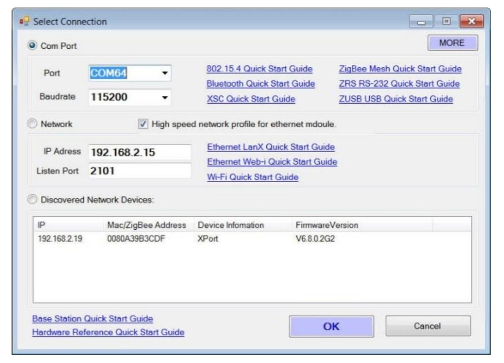
Step 4: Launch NCD Base Station software. The first window you will see is the Select Connection window. After a few seconds you should see your Ethernet controller appear under Discovered Network Devices. Once the device appears in the window double click on it to open its web interface in your browser. alternatively you can view attached devices on your network and open your browser then enter the controller’s IP address in the URL bar. This allows for configuration without base station.
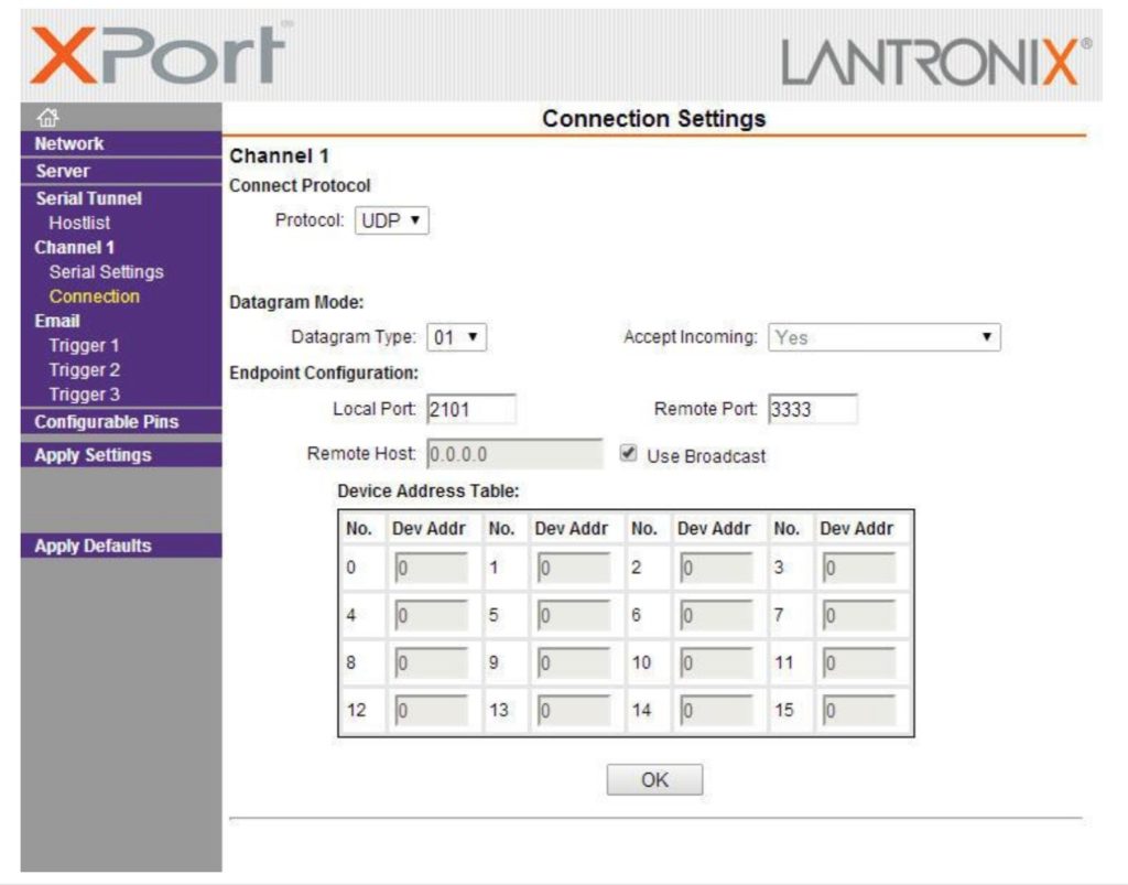
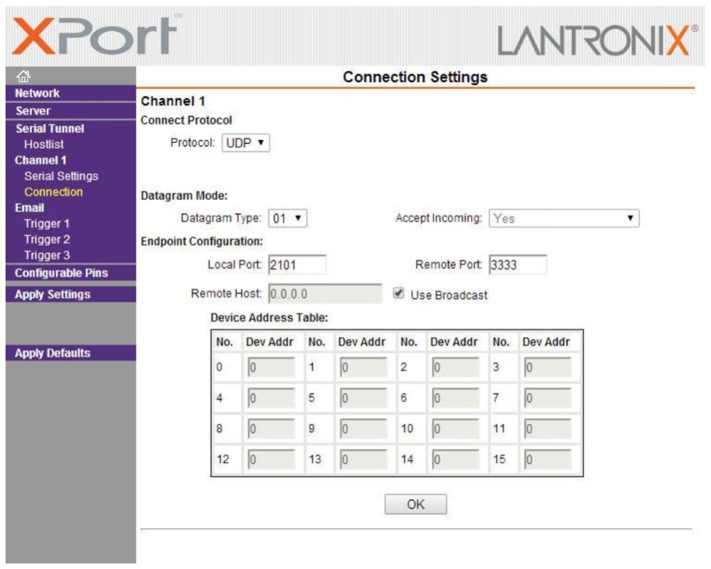
Step 5: If prompted for a password to log in simply click the enter button on your keyboard. Once you have the web interface open to the controller you can begin modifications to its notification method. By default your controller should be set to broadcast a UDP packet to all devices on the same network on port 3333. The picture below shows how this looks on the configuration in the web interface under the Connection Menu.
Step 6: Under this connection you can change any settings you see fit. You can change the notification packet destination to specify a particular IP address and you can send the packet via TCP or UDP on any port you wish. Most customers will find the default settings for sending the notification in a UDP broadcast to all devices on the network via port 3333 works quite well so don’t feel obligated to change any settings here if you do not wish to. The initial testing procedure below assumes you did not change any settings here.
Step 7: Setup is complete. Proceed to initial testing process below.
Initial Testing
Step 1: Make sure your push notification board is still connected to the same network as your windows computer and is still powered up.
Step 2: Install Com Operator Pal on your Windows computer: http://www.serialporttool.com/download/CommOperator/CommOpPal.zip.
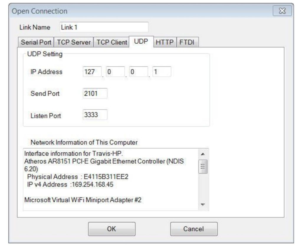
Step 3: Launch Com Operator Pal. You should see an Open connection window appear. Select the UDP tab, change the ListenPort to 3333, send port to 2101, do not worry about the IP Address field, then click the OK button.
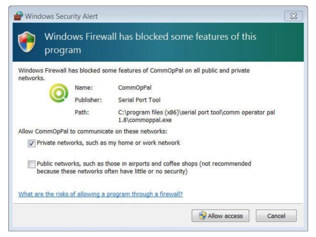
Step 4: After clicking ok you many see a Windows Security Alert. If you do simply click Allow Access.
Step 5: You should now see the Send/Receive window below.
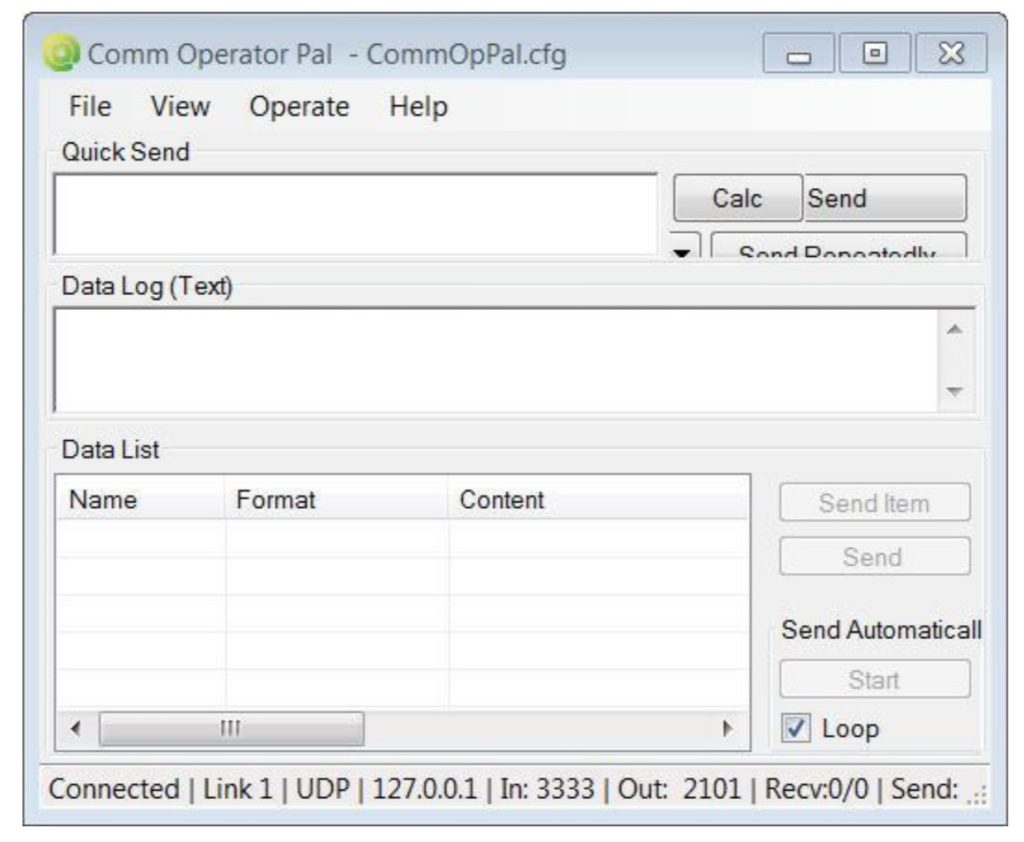
Step 6: Click the View Menu at the top of the window and set it to Decimal.
Step 7: Close any input on your Push Notification board. You should see data appear in Com Operator Pal under Data Log(Text). If you see data here than your setup is complete. If not please make sure you have the Open Connection settings configured properly for the setup in the Ethernet module if you changed any of those settings during setup.
Step 8: Setup and Initial Testing are now complete. Read further to learn more about the data being sent by the push notification board and how to use it.
Hardware Reference
Compatible Sensors (Understanding Inputs)
Warning:
Users must never apply any voltage to an input on PM series product!
Inputs are for dry contact closures only!
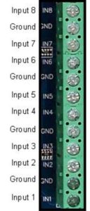
Inputs are capable of reading Contact Closure generating devices such as buttons and switches. A wire connected from the ground terminal to the input terminal would trigger the input, as this would be considered a contact closure. Any device that generates a dry contact closure can be used to trip the inputs on PM series controllers.
Push Notification Inputs play a vital role in the use of a PM series controller. Before we begin using the controller, it is essential that users understand the role of these inputs. Improper use of these inputs can cause Irreparable Damage to the PM controller.
Power Supply Specifications
PM controllers require a 12VAC or 12VDC power supply to power the logic and relays of the controller. The PWR12 is our stock power supply suitable for use with ALL PM Series controllers. While it is possible to operate from an automotive 13.8V power supply, higher voltages are not recommended. Additional power filtering may be required for proper operation in automotive electrical systems. The absolute minimum recommended operating voltage is 11VAC or 11VDC. PM controllers require approximately 100ma for standby and 60ma for each activated relay. Communication Modules may require up to an additional 240 ma, this is documented on the Electrical Specifications Page.
Power polarity is not important on the PM Series controllers. There is not positive or negative terminal. Simply apply power to the controller as it is convenient to make wired connections. The PM controller will rectify your power supply and attempt to filter noise to safe levels for proper operation.
Environmental Specifications
Certain components of a PM controller may run at temperatures exceeding 120° Degrees Fahrenheit. This is normal for a PM controller and does not indicate a defect.
The recommended operating temperature for all PM controllers is -25° to +85° C. This temperature rating is based on temperature specifications of the components used to build aPM controller and is not based on actual testing. We have speculated that PM controllers may be able to withstand lower temperatures due to the fact that PM controllers tend to have hot components in critical areas of the design.
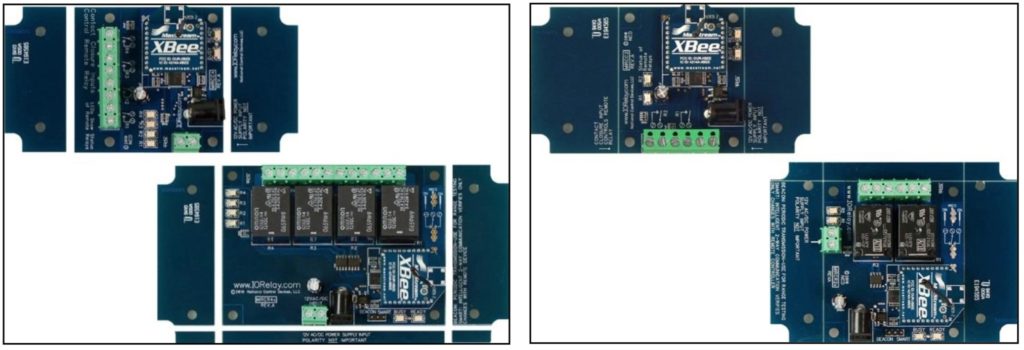
Break-Away Tabs
Physically, most MirC controllers are actually 2 sizes. When you receive your MirC, the unusual shape and size ensures the MirC can fit into a standard enclosure. Optionally, you can make the controller smaller by breaking away the outer tabs. Break-Away tabs are useful in applications where space may be a concern.This allows your MirC to offer the same functionality in the smallest possible profile.Break-Away tabs are unique to the NCD product line and are a standard option for most devices released in 2010 and later.
Before breaking the tabs on your controller, please be advised that your MirC controller will not be returnable for refund or credit if the Break-AwayTabs have been removed.
To break away the tabs, gently but firmly grab each break-away tab with a pair of pliers and bend the tab back and forth until it breaks away from the main circuit board. This will NOT damage the controller in any way.
Breaking the Tabs from a controller DOES NOT VOID the warranty. Please see the NCD return policy if you would like more information on the policies that apply to Surface Mount devices.
Communication Overview
Sensor Packet Breakdown
The packet transmittedby the controller contains22 bytes ofdata. Below is a breakdown of the packet:
Byte Position
| Byte | 0 | 1 | 2-3 | 4-9 | 10-17 | 18 | 19 | 20 | 21 |
| Data Type | Header | ID | F. Ver | MAC | User Def. | Status Type | Prior Status | Current State | Checksum |
Byte 0 is a header byte. This will always be 180 for PN series products.
Byte 1 is transmission id. This id will increase 1 increment for each broadcast sent by the controller. Note that this will reset after power cycle.
Bytes 2-3 indicate the controller’s firmware version. 01 00 would indicate v1.0
Bytes 4-9 indicate the Ethernet module’s Mac address. Convert these bytes to Hexadecimal bytes for Mac format.
Bytes 10-17 are user definable. This can be used for any purpose required by the customer. These bytes can be customized underScratch pad memory in Base Station.
Byte 18 indicates the transmission data type. For current PN products this will be 1 indicating this is the status of the contact closure inputs.
Byte 19 indicates the status of inputs prior to the input status change which triggered this notification.
Byte 20 indicates the status of inputs after the input status change which triggered this notification.
Byte 21 is a checksum for the whole packet. See API Codec guide which explains how this check sum is calculated.
ProXR Class Relay Controller Push Notification
ProXR Series relay controllers also allow for push notification capabilities over Ethernet. The following instructions apply only to ProxR Lite and ProXR Class controllers, and do not apply to “Blue” Push notification series controllers.
Input Configuration
Inputs on ProXR series controller can be configured to send notifications when the input is opened or closed, only when they are closed, or only when they are opened. This configuration is done through Base Station as follows:
Step 1: You must change the connection configuration for the Ethernet module for TCP. Base Station currently only supports communication to network devices via TCP socket (not UDP). To do this open the web interface to the Ethernet module by entering its IP address in your browser’s URL bar.
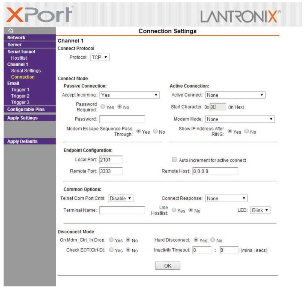
Step 2: Click the Connection menu on the left side of the web interface, you will more than likely see the setup configured for UDP like the picture below:
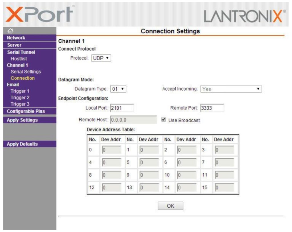
Step 3: Change configuration of the connection as shown in the window below, click the OK button, then click the Apply Settings menu on the left:
Step 4: Open Base Station, Select the Network Radio button on the Select Connection window. Enter the IP address of the Ethernet module in the IP address text field. Enter the Port defined as the TCP Listener port in the Ethernet module (by default this is set to 2101). Then click the OK button below.
Step 5: Base Station will communicate to the controller and display a window with control software options. Select AD8 Relay Activator/Event Generator.
Step 6: The AD8 Relay Activator/Event Generator window will now be displayed. You will notice that each input can be tied to a function. The functions are labeled for controlling relays but just know that rather than switch a relay we will be triggering the notification. Inputs should only be set to momentary or toggle at this time. If Input 1 functions is being configured you may set it to Momentarily Control Relay 1 or Toggle Relay 1. Do not set it to any other feature or set it to a different relay number as this will cause confusion.
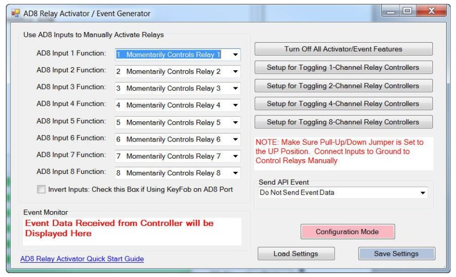
Step 7: Once settings are configured click the save settings button in the bottom right corner to save the changes to the controller.
Step 8: Set User Definable Transmitted Bytes if needed. Remainder of setup is concluded after User Definable Transmitted Bytes section. If you do not wish to define user bytes continue to the next page
User Definable Transmitted Bytes
8 bytes in the Notification packet are definable by the user. These bytes can be used in any way required by the user. Configuration of these bytes is done using Base Station as follows:
Step 1: Open Base Station; Select the Network Radio button on the Select Connection window. Enter the IP address of the WiFi module in the IP address text field. Enter the Port defined as the TCP Listener port in the WiFi module (by default this is set to 2101). Then click the OK button below.
Step 2: Base Station will communicate to the controller and display a window with control software options. Select Scratchpad Memory Command Set.
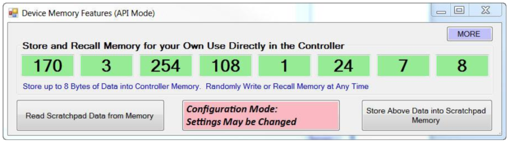
Step 3: A new window will appear with 8 byte positions. The user may change any of the 8 bytes as required.
Step 4: After configuration is complete click the Store Above Data into Scratchpad Memory to store the changes into the controller.
Advanced Setup Continued
Step 9: Once all configuration through Base Station is concluded you will need to reset the connection options in the device’s web interface. Open your browser and enter the controller’s IP address to open the Ethernet module’s setup.
Step 10: Click the Connection menu option on the left and change settings as shown below, click the OK button, then click the Apply Settings button on the left side of the window:
Step 11: Advanced Configuration is now complete.
Troubleshooting
Problem: Ethernet module will not associate with network.
Fix: Temporarily disable network security, there are known compatibility issues between.
Problem: Broadcast transmission from controller is not received on server/computer.
Fix:
- Make sure you do not have any type of antivirus software which could block TCP/UDP sockets (McAfee is known for this).
- Windows fire wall can also sometimes block these socket connections, you can open a port number in Windows Firewall under configuration.
- Check Settings in module for server connection. Ensure server is listening on the transmit port used by the controller. Only applicable if you specified an IP address in the connection settings under WEB interface setup.
- Make sure WiFi module is associated with network, the flashing green LED on the module indicates valid connection with the network.
- If server/computer is on a remote/sub network (separate network from the module) make sure port forwarding is configured correctly.
- Make sure sensor connected to controller is functioning properly using a continuity tester (voltmeter).