

Explore The Wireless Activity Detection Gen4
Device Overview
Introducing NCD’s Gen4 Industrial Wireless Activity Detector. Utilizing a wireless mesh networking architecture, this device offers an impressive wireless range of up to 2 miles. It incorporates a high-accuracy acceleration sensor that measures changes in acceleration to reliably detect mechanical movement (activity).
Upon detecting activity, the device immediately transmits a message to a remote gateway or modem, then returns to a sleep state for a pre-configured period. It makes extensive use of hardware interrupts to enter the lowest possible power state while sleeping, maximizing battery life. In addition to transmitting data when activity is detected, the sensor also sends regular “check-in” messages at set intervals. This ensures you always know the detector is online, fully operational, and actively monitoring.
- Industrial Grade Accelerometer with 3-axis for Activity Detection
- Configurable Activity Detection Parameters with Interrupts
- Configurable Acceleration Range ±2g to ±16g
- Configurable Interrupt Threshold
- Configurable Data Rate
- Configurable Interrupt Duration
- Customizable Interrupt Types with Combinations
- Wall-Mounted or Magnet
- Mounted IP65 Rated Enclosure
- 2 Mile Line-of-Sight Range with On-Board Antenna
- Superior LOS Range of up to 28 Miles with High-Gain Antennas
- Interface to Raspberry Pi, Microsoft® Azure®, Losant, and More
- Wireless Mesh Networking using DigiMesh®
- Open Communication Protocol for Easy Software Integration
- Power-Efficient Sleep Mode, Up to 10 Year Battery Life
Hardware Controls
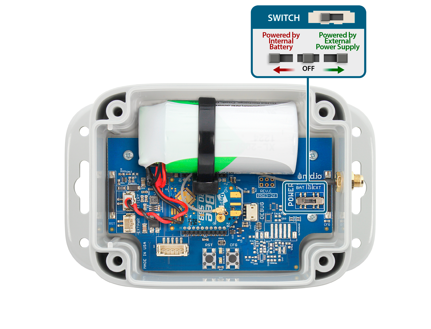
Power Switch
The power switch on this device has three positions:
- Battery Power (ON BATT)
- Off
- External Power (ON EXT)
The Battery Power position will use the onboard batteries to power the sensor and transmit data.
The Off position will power down all components of the sensor and no data will be transmitted
The External Power position will use the external power supply connected to the onboard barrel connector to power the sensor and transmit data.
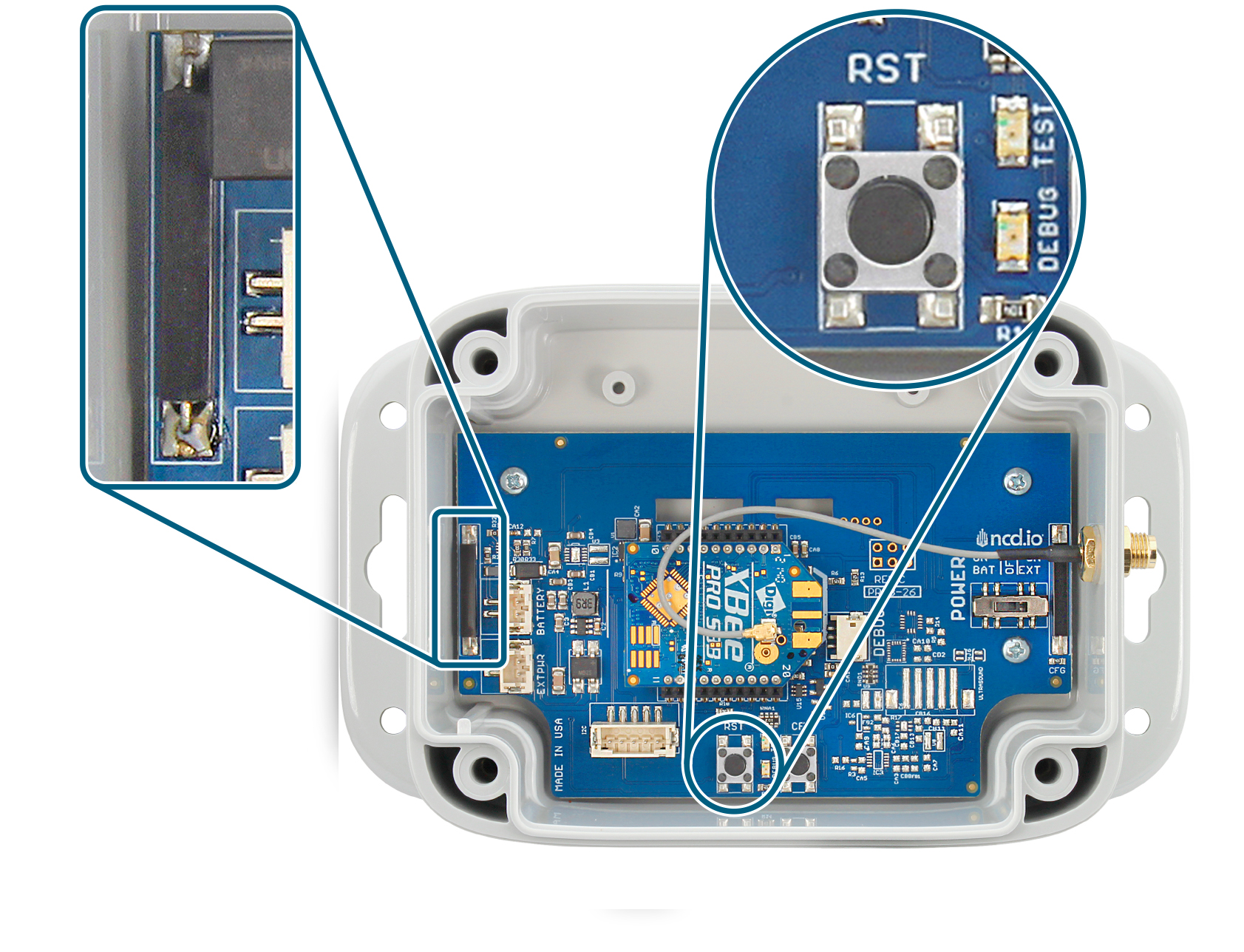
Reset Button and Magnetic Switch
The RESET button and Magnetic Switch will power cycle the sensor. When the sensor first powers up it will send a sensor_mode message with the mode of RUN.
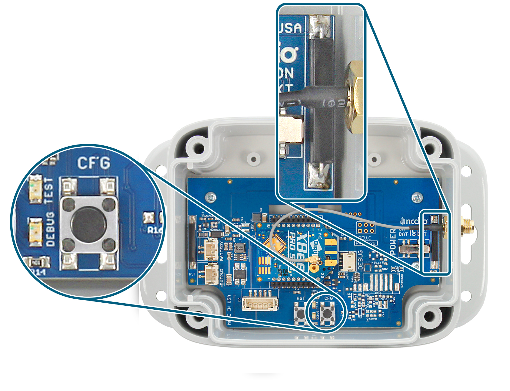
Configuration Button and Magnetic Switch
The Configuration Button (Labeled on board as CFG) and Magnetic Switch serves to test for the presence of power on the sensor. If the CFG button is pressed or Magnetic Switch is activated the TEST LED on the board will light up indicating that the board has power. If no LED comes on check that the Power Switch is in the correct position and that the battery/power supply is good.
Hardware Mode Selection
Run Mode
Run Mode is the default state of the sensor when powered up. No hardware interaction is necessary to enter this state other than power. Pressing the Reset button or activating Magnetic Switch will restart the sensor and put it in the RUN Mode state if no other buttons are pressed.
Sync/Configuration Mode
Configuration or Sync Mode is the state in which the sensor enters in order to change the sensor’s configurable parameters such as; Motion Threshold, Motion Duration, Reporting Interval, Transmission Power, Network ID,etc.
You can enter in this mode manually by pressing and releasing the RESET button or activating Magnetic Switch, device will enters RUN mode, then it will transmit sensor data and finally enters into configuration mode (sync mode). Sensor enters into configuration mode automatically every 1 hour.
This is a temporary mode that is not intended for long-term operation. device will returns automatically to Run mode after a successful configuration in order to resume normal operations.
Factory Default/Reset
A Factory Reset of the sensor will revert all changes and configurations made to the sensor to their default settings from the Factory. Immediately after a factory reset the sensor will go into Configuration Mode in order to be reconfigured with the desired settings. There are two option for Factory reset your sensor. You can either use the physical buttons or the magnetic switches. Refer to the appropriate section below for instructions on how to initiate the process for each case.
Using Buttons
- Press and release the RESET button
- Wait for a second, then press and hold the CONFIGURATION button
- Hold the CONFIGURATION button for about 20 seconds
- Release the CONFIGURATION button
- Wait for 3-5 seconds
- Press and release the RESET button.
Using Magnetic Switches
You can perform a Factory Reset using the following sequence:
- Move a magnet near the RESET switch and then move it away
- Wait for 1 second
- Hold the magnet near the CONFIGURATION switch for about 20 seconds
- Move the Magnet away from the CONFIGURATION switch
- Wait for 3-5 seconds
- Move a magnet near the RESET switch and then move it away
Default Factory Configuration
| Parameter | Default Value | Unit | Note |
|---|---|---|---|
| Motion Threshold | 200 | mg | The transmitted message will have a msg_type property of 'motion'. Valid range: 0-23622mg. |
| Motion Duration | 20 | milliseconds | Valid range: 0-65535 msec |
| Max Motion Tx Per Interval | 1 | Valid Range: 1-30 | |
| Data Rate | 100 | Hz | |
| Full Scale Range | ±2 | g | |
| Enable Axes | All Enabled | ||
| Motion Trigger Logic | OR Mode | OR Mode (Any Axis): The sensor sends an alert if any single axis crosses the defined threshold. AND Mode (All Selected Axes): The sensor sends an alert only if all enabled axes cross the threshold at the exact same time. |
Software Integration - Node-Red Overview
We built our primary software drivers into a software system called Node-Red. Node-Red is a visual based drag-and-drop low/no code flow builder. It allows you to build simple or complex logic and data dissemination applications quickly and easily. It can integrate with third party software/cloud services using a number of protocols such as MQTT, HTTP(S), TCP, UDP, and OPC UA.
For more information and a general introduction on what Node-Red is and how it works you can view Node-Red’s official web site at https://nodered.org/.
All Enterprise Gateway we offer will come with Node-Red and our library running as a service by default to allow quick and easy access to Node-Red and the sensor data from our sensors. If you are using your own gateway or computer you will need a USB or Ethernet Modem, Node-Red, and our library @ncd-io/node-red-enterprise-sensors.
You can find our library on Node-Red with the name: @ncd-io/node-red-enterprise-sensors
In this section will will go over the nodes introduced by our library, what kind of data they will provide your flow, and how to use them.
Wireless Gateway Nodes
Wireless Gateway Nodes are a virtual representation of the wireless protocol connected to your Gateway. They will output all incoming data from the wireless network and all of the sensors on that network into the connected flows from a single entry point.
This is the recommended method for ingesting data from large numbers of sensors at a single location in order to simplify data handling and reduce the complexity of the resulting flow.
Wireless Gateway Node Statuses
Wireless Gateway nodes have multiple states they can show in Node-Red to indicate their current mode or functionality.
Wireless Gateway Ready State
When the Wireless Gateway Node’s status indicates “Ready”, as shown in the picture on the right, it means that the wireless network is successfully connected to Node-Red and is ready to receive data from the sensor(s).
Sensors that support SYNC messages can be automatically configured while in this mode if a corresponding Wireless Device node is configured to do so. See section Sensor Configuration Processes for more information.

Wireless Gateway Failed to Connect State
When the Wireless Gateway Node’s status indicates “Failed to Connect”, as shown in the picture on the right, it means that Node-Red was unable to connect to the wireless network. This usually indicates that incorrect settings were used while configuring the Gateway.
For more information on configuring your Wireless Gateway Node’s communications see section Wireless Gateway Node Configuration.
For more information on troubleshooting your Wireless Gateway Node’s communications see section Troubleshooting

Wireless Gateway Connecting State
When the Wireless Gateway Node’s status indicates “Connecting…”, as shown in the picture on the right, it means that Node-Red is waiting to initialize the connection to the Wireless Network. This state will last for 5 seconds before Node-Red attempts to open communication to ensure that all hardware and software is initialized.
No incoming or outgoing data will be handled while in this state.

Wireless Gateway No State
When the Wireless Gateway Node has no status indication, as shown in the picture on the right, it means that the node is not configured properly and no communications have been indicated for the node. For more information on configuring the Wireless Gateway Node see section Wireless Gateway Node Configuration.

Wireless Gateway Node Messages
All messages from the Wireless Gateway Node will come through as Javascript Objects and are output by default as JSON representations when viewed or sent over most protocols. In Node-Red the primary object to reference the message will be msg. You can access sub-properties using msg.payload or msg.payload.nodeId etc.
modem_mac Message
A modem_mac message indicates the unique address of the wireless module connected to the Wireless Gateway Node. This message is sent when Node-RED is deployed and when the Wireless Gateway is put into Configuration Mode or Ready Mode by using the embedded Wireless Gateway node button. An example modem_mac message can be found on the right.
- topic
- Indicates the type of message this is
- payload
- Contains the unique address of the wireless module on the Wireless Gateway Node
- time
- Timestamp of the message
					{
  "topic": "modem_mac",
  "payload": "00:13:A2:00:41:F5:2C:D3",
  "time": 1721424259706,
  "_msgid": "83ad39df1328dea7"
}
Wireless Gateway RUN Message
A RUN message received simply indicates that the sensor indicated in the msg.payload.mac is powered up and communicating with the wireless network. An example RUN message can be found on the right.
- topic
- Indicates the type of message this is
- payload
- Contains the primary data of the message
- payload.mac
- Indicates the unique address of the sensor sending the mode message
- payload.type
- Indicates the type of sensor sending the mode message
- payload.nodeId
- A user configurable parameter allowing a user to input a simple id for a particular sensor
- payload.mode
- indicates the current mode of the sensor
- payload.lastHeard
- Timestamp of the message
					{
  "topic": "sensor_mode",
  "payload": {
    "mac": "00:13:a2:00:42:37:73:52",
    "type": 24,
    "nodeId": 0,
    "mode": "RUN",
    "lastHeard": 1721424191056
  },
  "time": 1721424191056,
  "_msgid": "f41dad7923ece27c"
}
Wireless Gateway Processed Sensor Data Message
Sensor data is the primary message that will come from a Wireless Gateway Node. These messages can be discerned from other message types by the topic which will always be “sensor_data”
To the right is an example of a Sensor Data message.
- nodeID
- A user configurable parameter allowing a user to input a simple id for a particular sensor
- For a unique identifier it is recommended to use the “addr” property as it is tied to the individual sensor’s wireless module and will always be unique
- firmware
- This identifies the firmware version of the sensor sending the packet
- battery
- The current voltage level of the batteries at the time of transmission
- The batteries that come with the sensors drop off quickly once they reach 2.6 volts
- battery_percent
- The current battery percent at the time of transmission
- counter
- The number of transmissions since boot or counter rollover
- The counter will rollover after a counter value of 255
- sensor_type
- The machine identifiable type of the sensor
- It is recommended to use this property to dictate dashboard generation and/or data integrity checks
- sensor_data
- Object containing all sensor data related to this sensor
- See section msg.payload.sensor_data Breakdown for more information
- sensor_name
- Human Readable Sensor Type Identifier
- type
- An easily passed message type declaration
- This property will be a duplicate of msg.topic
- addr
- The unique identifier of the sensor that transmitted the data
- received
- Epoch indicator of when the data was received by Node-Red
- original
- Auxiliary information on the packet and underlying protocol
- modem_mac
- The unique identifier of the Gateway/Modem that received the data
- Primarily used to tie locations/projects to sensors/sensor data
					{
  "topic": "sensor_data",
  "payload": {
    "nodeId": 0,
    "firmware": 7,
    "battery": "3.28",
    "battery_percent": "98.56",
    "counter": 26,
    "sensor_type": 24,
    "sensor_data": {
      "status": "valid",
      "msg_type": "regular",
      "acc_x": 0,
      "acc_y": 0,
      "acc_z": 0
    },
    "sensor_name": "Activity Detection",
    "type": "sensor_data",
    "addr": "00:13:a2:00:42:37:73:52",
    "received": 1721424191583,
    "original": {...},
    "modem_mac": "00:13:A2:00:41:F5:2C:D3"
  },
  "time": 1721424191584,
  "_msgid": "d7f3341ef39225df"
}
Wireless Gateway Processed Sensor Data Breakdown
- status
- Indicate the sensor status, it reports valid when success and invalid when sensor error.
- msg_type
- Indicates the sensor data message type:
- regular – data sent at regular interval (defined by user – Data transmission interval).
- motion – data triggered by the vibration crossing a predefined threshold.
- Indicates the sensor data message type:
- acc_x
- The RMS Acceleration over the X axis in G.
- acc_y
- The RMS Acceleration over the Y axis in G.
- acc_z
- The RMS Acceleration over the Z axis in G.
Wireless Gateway Sync Check In Message
This sync_check_in message reports sensor information and allows for sync initialization if configuration changes are necessary.
A sync_check_in message indicates that the sensor is in RUN mode, but is entering a temporary state where it can be configured. The sensor will send the sync_check_in message on boot (after RUN and sensor_data messages) and once an hour after boot to check in. Once the sensor sends a sync_check_in message Node-RED has 2 seconds to respond with a configuration Master Command.
If Node-RED has a Wireless Device node with Mac Address, Auto Config and OTF Config selected corresponding to the sensor that sent the sync_check_in message then Node-RED will begin to configure that sensor.
An example sync check-in message can be found on the right.
- topic
- Indicates the message is a sync message
- payload
- Contains the primary data of the message
- payload.type
- Indicates the type of sync message.
- payload.address
- Indicates the unique address of the sensor sending the sync message
- payload.sensor_type
- Indicates the type of sensor sending the mode message
- payload.human_readable object
- It contains the human readable data, display configuration set up on the sensor at the time of the sync transmission.
- payload.human_readable.core_version
- Indicates the board core version.
- payload.human_readable.firmware_version
- The actual firmware version running on device.
- payload.human_readable.sensor_type
- Displays the sensor type.
- payload.human_readable.tx_lifetime_counter
- Tracks the total number of data packets transmitted by the CPU since the device first booted
- payload.human_readable.hardware_id
- This value indicates the hardware version of the device
- payload.human_readable.network_id
- This value indicates the network Id configured on the device, by default all ncd devices uses 0x7FFF.
- payload.human_readable.destination_address
- Shows the current destination address configured on the sensor. The default setting is broadcast mode “00:00:FF:FF”
- payload.human_readable.node_id
- A user configurable parameter allowing a user to input a simple id for a particular sensor
- payload.human_readable.report_rate
- Specifies the data transmission interval in seconds.
- payload.human_readable.output_data_rate
- Specifies the how many samples the output data has.
- payload.human_readable.motion_duration
- Specifies the amount of time in milliseconds that motion/impact must continuously persist before triggering an alert.
- payload.human_readable.motion_trigger_logic
- Specifies how the sensor handles the X, Y, and Z axes to trigger an immediate sensor data transmission (motion).
- payload.human_readable.motion_threshold
- Specifies the threshold for the sensor to trigger a data transmission.
- payload.human_readable.enable_axis_x
- Specifies if x axis is enabled or disabled.
- payload.human_readable.enable_axis_y
- Specifies if y axis is enabled or disabled.
- payload.human_readable.enable_axis_z
- Specifies if z axis is enabled or disabled.
- payload.human_readable.full_scale_range
- Specifies the actual FSR configured
- payload.human_readable.max_motion_tx_per_interval
- Specifies the number of times device will transmit a motion data message due to motion triggers per interval.
- payload.machine_values
- The Raw data the sensor reports
- description
- Indicates information about the current sync message
					{
  "topic": "sync",
  "payload": {
    "type": "sync_check_in",
    "address": "00:13:a2:00:42:35:89:86",
    "sensor_type": 24,
    "human_readable": {
      "core_version": 23,
      "firmware_version": 7,
      "sensor_type": 24,
      "tx_lifetime_counter": 13,
      "hardware_id": {
        "data": [ 99, 61, 0]
      },
     "network_id": "7fff",
     "destination_address": "0000ffff",
     "node_id": 0,
     "report_rate": 900,
     "output_data_rate": "100Hz",
     "motion_duration": "20msec",
     "motion_trigger_logic": "OR Mode",
     "motion_threshold": "800mg",
     "enable_axis_x": "Enabled",
     "enable_axis_y": "Enabled",
     "enable_axis_z": "Enabled",
     "full_scale_range": "±4g",
     "max_motion_tx_per_interval": 5
    },
    "machine_values": { ... }
  },
  "description" : "...",
  "packet_info": {
      "ack": 0,
      "broadcast": 0,
      "type": ""
      }
  "time": 1781217138869,
  "_msgid": "33fd88e3ea54492c"
}
Wireless Gateway Assertion Reason Message
A Assertion Reason message will be used for debugging purpose, It will show the code line number and function name.
An example Assertion Reason message can be found on the right.
					{
  "topic": "assert_rsn",
  "payload": {
    "addr": "00:13:a2:00:42:37:73:52",
    "type": 24,
    "nodeId": 0,
    "line_number": 1435,
    "function_name": "app_start_fly_timer"
  },
  "time": 1721424191767,
  "_msgid": "5f6f01b6651b2f82"
}
Wireless Node Configuration
Wireless Gateway Edit Pane
You can edit a Wireless Gateway node by double clicking on it once placed in a flow. Below is a description of the primary elements of this edit pane corresponding to the elements numbered to the right.
- Name
- An arbitrary name given to this node
- Serial Device*
- A drop down to choose between configured communication interfaces
- The default Serial Device for our Enterprise Gateways is “/dev/ttymxc2”
- To add a new configuration option you will want to choose “Add new ncd-gateway-config…” from this dropdown
- Serial Device Edit Icon
- Clicking this icon will take you to a submenu to edit the particulars of the device chosen in the Serial Device dropdown
- To add a new configuration option you will want to choose “Add new ncd-gateway-config…” from this dropdown
- For More information on the submenu this icon bring up see section ncd-gateway-config Nodes
- Output data from Unknown Devices
- Enabling this feature allows other devices using the Digimesh wireless protocol to send their data to Node-Red
- When selected, data from unknown devices will be output from a secondary output

Wireless Device Nodes
Wireless Device nodes are a virtual representation of a single sensor or a type of sensor. These nodes will output all sensor data and configuration messages from the sensor.
Wireless Device nodes are the primary method of configuring individual or groups of sensors. Their message structure is slightly different from the data coming from a Wireless Gateway.
Wireless Device Node Statuses
The Wireless Device node will display a status based on the last message received to easily identify what is going on with the sensor. Below we will cover each status the Wireless Device node can enter and what it means.
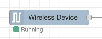
Running Mode
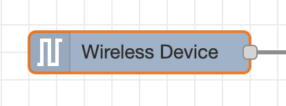
When the Wireless Sensor Node’s status indicates “Running”, as shown in the picture on the right, it means that the wireless sensor has successfully sent at least one packet to the configured Wireless Network. The packet must be a sensor_mode message with a mode of RUN or a sensor_data message.
No Mode
When the Wireless Sensor Node has no status, as shown in the picture on the right, it means that the wireless sensor has not sent a packet over the wireless network since Node-Red was run. The packet must be a sensor_mode message with a mode of RUN or a sensor_data message.
FLY Mode
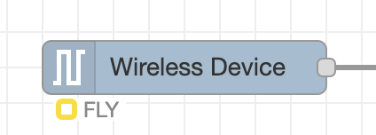
When the Wireless Sensor Node’s status indicates “FLY,” as shown in the picture to the right, it means the sensor has sent a sync message to check in for an Over-the-Air (OTA) configuration, and the synchronization process has been successfully completed.
Wireless Device Node Messages
Wireless Device Sensor Data Message
Sensor data is the primary message that will come from a Wireless Gateway Node. These messages can be discerned from other message types by the topic which will always be “sensor_data”
To the right is an example of a Sensor Data message.
- topic
- Indicates the type of message this is
- data
- Contains the sensor data and all other pertinent details of the sensor
- data.nodeID
- A user configurable parameter allowing a user to input a simple id for a particular sensor
- For a unique identifier it is recommended to use the msg.data.addr property as it is tied to the individual sensor’s wireless module and will always be unique
- data.firmware
- This identifies the firmware version of the sensor sending the packet
- data.battery
- The current voltage level of the batteries at the time of transmission
- The batteries that come with the sensors drop off quickly once they reach 2.6 volts
- data.battery_percentage
- The current battery percent at the time of transmission
- data.counter
- The number of transmissions since boot or counter rollover
- The counter will rollover after a counter value of 255
- data.sensor_type
- The machine identifiable type of the sensor
- It is recommended to use this property to dictate dashboard generation and/or data integrity checks
- data.sensor_data
- Object containing all sensor data related to this sensor
- This property is a duplicate of the payload property
- data.sensor_name
- Human Readable Sensor Type Identifier
- data.type
- An easily passed message type declaration
- This property will be a duplicate of msg.topic
- data.addr
- The unique identifier of the sensor that transmitted the data
- data.received
- Timestamp of the message
- data.original
- Auxiliary information on the packet and underlying protocol
- data.modem_mac
- The unique identifier of the Gateway/Modem that received the data
- Primarily used to tie locations/projects to sensors/sensor data
- payload
- Object containing all sensor data related to this sensor
- See msg.payload Breakdown for more information
- time
- Timestamp of the message
					{
  "topic": "sensor_data",
  "data": {
    "nodeId": 0,
    "firmware": 10,
    "battery": "3.28",
    "battery_percent": "98.56",
    "counter": 26,
    "sensor_type": 24,
    "sensor_data": {
      "status": "valid",
      "msg_type": "regular",
      "acc_x": 0,
      "acc_y": 0,
      "acc_z": 0
    },
    "sensor_name": "Activity Detection",
    "type": "sensor_data",
    "addr": "00:13:a2:00:42:37:73:52",
    "received": 1721424191583,
    "original": {...},
    "modem_mac": "00:13:A2:00:41:F5:2C:D3"
  },
  "payload": {
      "status": "valid",
      "msg_type": "regular",
      "acc_x": 0,
      "acc_y": 0,
      "acc_z": 0
  },
  "time": 1721424191584,
  "_msgid": "48e99332fc104565"
}
Wireless Device Sensor Data Breakdown
- status
- Indicate the sensor status, it reports valid when success and invalid when sensor error.
- msg_type
- Indicates the sensor data message type:
- regular – data sent at regular interval (defined by user – Data transmission interval).
- motion – data triggered by the vibration crossing a predefined threshold.
- Indicates the sensor data message type:
- acc_x
- The RMS Acceleration over the X axis in G.
- acc_y
- The RMS Acceleration over the Y axis in G.
- acc_z
- The RMS Acceleration over the Z axis in G.
Sync Check In Message
This sync_check_in message reports sensor information and allows for sync initialization if configuration changes are necessary.
A sync_check_in message indicates that the sensor is in RUN mode, but is entering a temporary state where it can be configured. The sensor will send the sync_check_in message on boot (after RUN and sensor_data messages) and once an hour after boot to check in. Once the sensor sends a sync_check_in message Node-RED has 2 seconds to respond with a configuration Master Command.
If Node-RED has a Wireless Device node with Mac Address, Auto Config and OTF Config selected corresponding to the sensor that sent the sync_check_in message then Node-RED will begin to configure that sensor.
					{
  "topic": "sync",
  "payload": {
    "type": "sync_check_in",
    "address": "00:13:a2:00:42:35:89:86",
    "sensor_type": 24,
    "human_readable": {
      "core_version": 23,
      "firmware_version": 7,
      "sensor_type": 24,
      "tx_lifetime_counter": 13,
      "hardware_id": {
        "data": [ 99, 61, 0]
      },
     "network_id": "7fff",
     "destination_address": "0000ffff",
     "node_id": 0,
     "report_rate": 900,
     "output_data_rate": "100Hz",
     "motion_duration": "20msec",
     "motion_trigger_logic": "OR Mode",
     "motion_threshold": "800mg",
     "enable_axis_x": "Enabled",
     "enable_axis_y": "Enabled",
     "enable_axis_z": "Enabled",
     "full_scale_range": "±4g",
     "max_motion_tx_per_interval": 5
    },
    "machine_values": { ... }
  },
  "description" : "...",
  "packet_info": {
      "ack": 0,
      "broadcast": 0,
      "type": ""
      }
  "time": 1781217138869,
  "_msgid": "33fd88e3ea54492c"
}
Sync Acknowledgment Message
A sync acknowledgment is received from the sensor in response to a configuration command. This message provides the current sensor status or reports any errors encountered during the configuration process. You may verify the current sensor configuration by examining the human_readable property within the message.
An example of a Sync Acknowledgment message is provided for your reference on the right.
					{
  "topic": "sync",
  "type": "sync_acknowledgment",
  "address": "00:13:a2:00:42:35:89:86",
  "sensor_type": 24,
  "payload": {
    "type": "sync_acknowledgment",
    "address": "00:13:a2:00:42:35:89:86",
    "sensor_type": 24,
    "response_bytes": [ ... ],
    "human_readable": { ... },
    "machine_values": { ... }
  },
  "description" : "...",
  "sent": [...],
  "packet_info": {
      "ack": 0,
      "broadcast": 0,
      "type": ""
      },
  "time": 1781217138869,
  "_msgid": "33fd88e3ea54492c"
}
Sync End Message
Sync process finished. Sensor is reporting its new values after Sync and resuming normal operations.
User can find the new settings after sync into “human_readable” property.
					{
  "topic": "sync",
  "type": "sync_end",
  "address": "00:13:a2:00:42:35:89:86",
  "sensor_type": 24,
  "payload": {
    "type": "sync_end",
    "address": "00:13:a2:00:42:35:89:86",
    "sensor_type": 24,
    "human_readable": { ... },
    "machine_values": { ... }
  },
  "description" : "...",
  "sent": [...],
  "packet_info": {
      "ack": 0,
      "broadcast": 0,
      "type": ""
      },
  "time": 1781217138869,
  "_msgid": "33fd88e3ea54492c"
}
Sync Response Success Message
Indicates that the sync configuration is complete and displays the specific values and properties applied to the settings.
					{
  "topic": "sync",
  "type": "sync_response",
  "address": "00:13:a2:00:42:35:89:86",
  "sensor_type": 24,
  "payload": {
    "address": "00:13:a2:00:42:35:89:86",
    "sensor_type": 24,
    "values": { ... },
    "pass": { ... },
    "status": "Success",
    "exit_otn_mode": { ... }
    },
  "time": 1781217138869,
  "_msgid": "33fd88e3ea54492c"
}
Sync Response Skip Message
A “Sync Response Skip” message indicates that the settings currently active within the corresponding Wireless Device node already match the sensor’s actual configuration. Consequently, the library bypasses the synchronization process. This functionality allows the library to verify if the sensor’s reported configuration aligns with the desired parameters, thereby optimizing the process by skipping redundant updates.
If you encounter this message, it confirms that the sensor is already configured with the desired settings as defined in the sync message.
					{
  "topic": "sync",
  "type": "sync_response",
  "address": "00:13:a2:00:42:35:89:86",
  "sensor_type": 24,
  "payload": {
    "address": "00:13:a2:00:42:35:89:86",
    "sensor_type": 24,
    "info": "Reported configurations match desired configurations. Skipping Sync."
    },
  "time": 1781217138869,
  "_msgid": "33fd88e3ea54492c"
}
Configuration Options
Our Node-Red library lets you configure any of sensor easily, simply by adjusting a few fields in your Node-RED flow and triggering a configuration update waiting for a FLY (sync) message sent every hour during normal operations (or when the device is reset).
You can edit a Wireless Device node by double clicking the node once it is placed in a flow.
Primary Configurations
These configurations are responsible for configuring the Wireless Device node and how node-red should interact with the sensor.
- Name
- Arbitrary name of this node
- Primarily used for easy identification in the flow
- Serial Device*
- The primary communication interface used to receive data from the sensor
- Clicking the edit icon will take you to a submenu to edit the particulars of the device chosen in the Serial Device dropdown
- To add a new configuration option you will want to choose “Add new ncd-gateway-config…” from this dropdown
- For More information on the submenu the edit icon brings up see section ncd-gateway-config Nodes
- Serial Device for Config
- A secondary communication interface used to configure sensors without losing sensor data
- If no option is selected the communication interface selected under Serial Device will be used for configuration
- A second modem will be required to make full use of this option
- Mac Address*
- Using this field allows you to choose a specific sensor that corresponds to this Wireless Device node
- A search icon on the right can be clicked to search for Wireless Devices that the Serial Device has heard from to auto fill information for that device
- Sensor Type*
- This field limits the sensors that correspond to this Wireless Device node to a particular type of sensor
- Auto Config
- Checking the box next to this field tells Node-Red that the sensor(s) corresponding to this Wireless Device node should be configured when put into Configuration Mode manually
- OTF Config
- Checking the box next to this field AND having Auto Config checked tells Node-Red that the sensor(s) corresponding to this Wireless Device node should be configured when a FLY message is detected
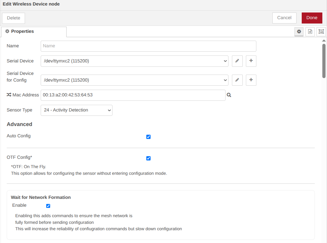
- Wait for Network Formation
- This option sends three commands to all local devices on the wireless network to help form the mesh network
- Destination Address
- This option will tell the sensor to ONLY send its data to a single receiver
- For more information on how to get the Address of the receiver module connected to Node-Red see section Wireless Gateway modem_mac Message
- Network ID
- This option allows you to change the Network ID that the sensor will use to report its data while in RUN module
- You will need to make sure that a Gateway or Modem is configured to use this network ID in order to receive sensor data from it after configuration
- Node ID
- Node ID allows you to set an easy to understand unique ID for a particular sensor
- Power
- This option allows you to set the transmission power level of the sensor
- Retries
- Sets the maximum number of retries the sensor will attempt before considering a packet transmission failed

Sensor Specific Configurations
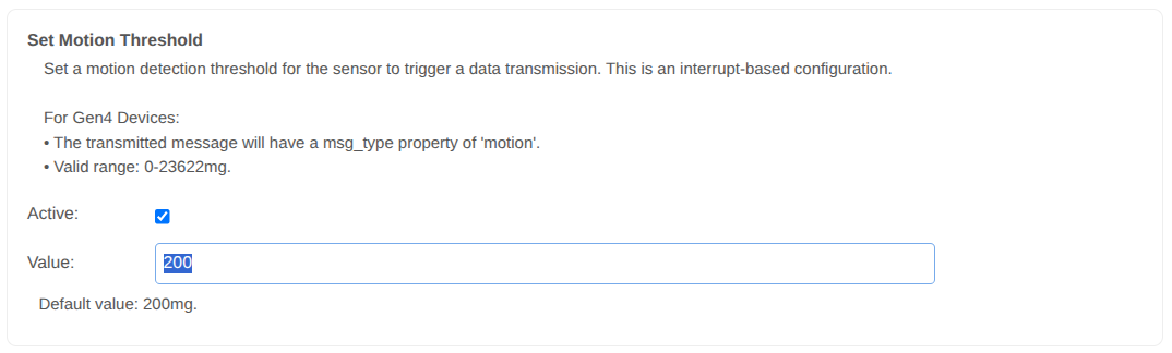
Set Motion Threshold
Set a motion detection threshold for the sensor to trigger a data transmission. This is an interrupt-based configuration.
• The transmitted message will have a msg_type property of ‘motion’.
• Valid range: 0-23622mg.
Default value: 200mg.
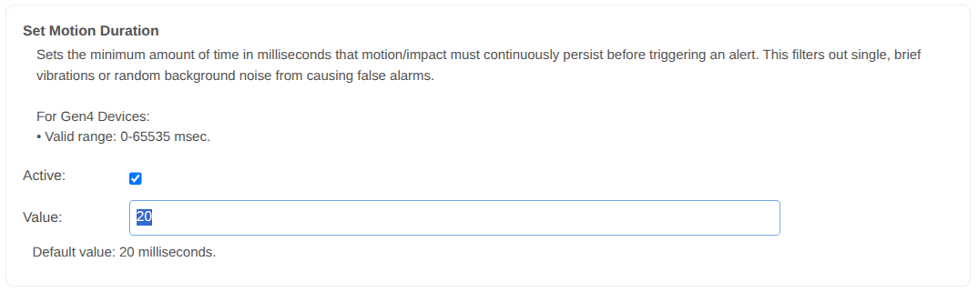
Set Motion Duration
Sets the minimum amount of time in milliseconds that motion/impact must continuously persist before triggering an alert. This filters out single, brief vibrations or random background noise from causing false alarms.
• Valid range: 0-65535 msec.
Default value: 20 milliseconds.
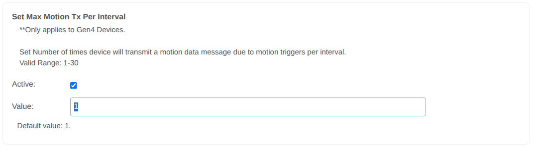
Set Max Motion Tx Per Interval
Set Number of times device will transmit a motion data message due to motion triggers per interval.
Valid Range: 1-30
Default value: 1.
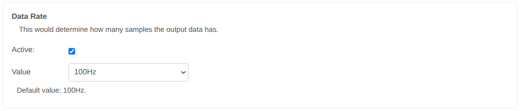
Data Rate
This would determine how many samples the output data has.
Default value: 100Hz.
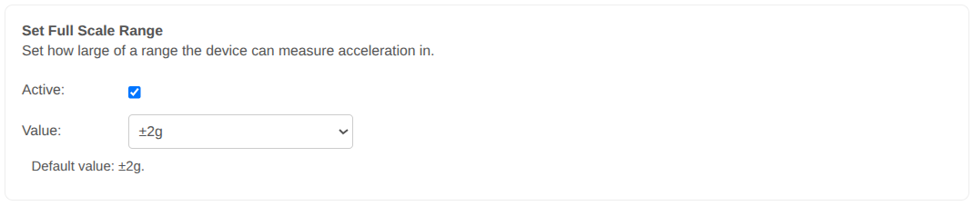
Set Full Scale Range
Set how large of a range the device can measure acceleration in.
Default value: ±2g.
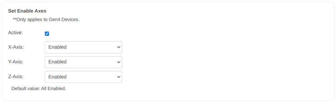
Set Enable Axes
Enable or Disable the individual Axes; X, Y or Z.
Default value: All Enabled.
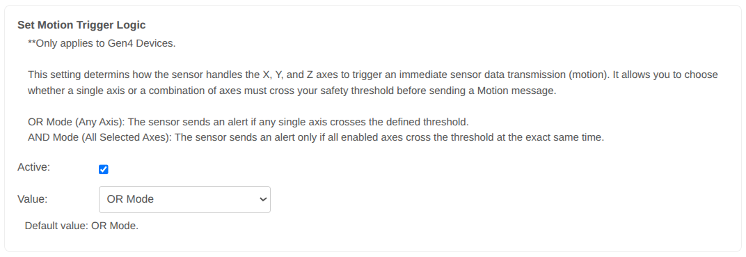
Set Motion Trigger Logic
This setting determins how the sensor handles the X, Y, and Z axes to trigger an immediate sensor data transmission (motion). It allows you to choose whether a single axis or a combination of axes must cross your safety threshold before sending a Motion message.
OR Mode (Any Axis): The sensor sends an alert if any single axis crosses the defined threshold.
AND Mode (All Selected Axes): The sensor sends an alert only if all enabled axes cross the threshold at the exact same time.
Default value: OR Mode.
Sensor Configuration Process
OTF Automatic Configuration
This sensor supports configuration while in Run Mode. We call this configuration OTF or On the Fly. This configuration is initiated by a SYNC message from the Sensor with the topic of sync. These messages are sent over the standard Run Mode wireless network so there is no need to change the Wireless Gateway nodes mode or manually manipulate the buttons on the sensor.
Sync messages are sent once an hour and on boot and tell Node-RED that the sensor is ready for configuration changes. Node-RED has two seconds to respond with a configuration command or extend this temporary configuration mode.
If you have a Wireless Device node with Mac address, Auto Config and OTF Config corresponding to the sensor that sent the sync message then Node-Red will begin configuring that sensor according to the settings entered on the Wireless Device node.
See section Primary Wireless Device Node Configurations for more information on how to set up a Wireless Device to configure a sensor.
Example Auto Configuration Process
If you have entered the sensor Mac Address, selected the Auto Config and OTF Config boxes, your sensor will pick up any configuration changes you have made to the Sensor Specific parameters and automatically apply them.
This process is not immediate and requires the device send a sync Message to the Gateway (this happens once every hour or when the device is reset).
Once the sync message has been received the device will enter OTN mode (indicated by a corresponding message) and update any parameters that have been changed.
Once done the device will continue its normal operating with the updated parameter values.
Let us look at an example to better illustrate how the process should work out.
Step 1
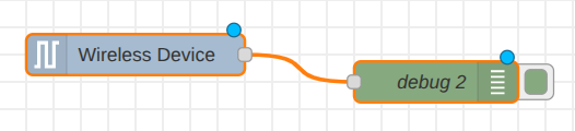
Draw and drop a Wireless Device node and connect a debug node at the Wireless Device node, then double click on Wireless Device node to access its properties. Enter the Mac Address of the target sensor, check the two boxes, the one next to “Auto Config” and the one next to “OTF Config”. This will allow the device to work in a mode where it will Automatically pick up the configuration changes.
Step 2
Select the parameter you want to modify.
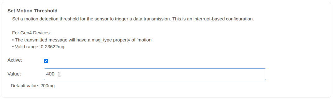
Let’s go to the “Motion Threshold” and change its value. This parameter determines the motion detection threshold for the sensor to trigger a sensor data transmission.
The default value is 200mg, let’s change it to 400 mg.
Make sure you check the “Active” check box, this will let the sensor know that it needs to update this parameter.
Enter the value into text input, in this case 400.
Press the “Done” button to close the Wireless Device node.
Press the “Deploy” button so you can update the flow.
Step 3
Reset the sensor in order to trigger a sync message (configuration mode).
(this will speed things up so you don’t need to wait for the 1 hour automatic sync message time).
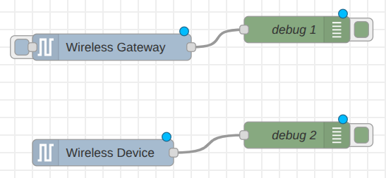
You will receive a series of messages into debug window, which are normally sent after deploy and the sensor starts (modem_mac, RUN, sensor_data, then sync_check_in).
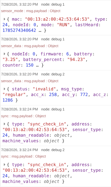
The most important element here is the sync_check_in message, which reports the device’s current configuration at the moment it is transmitted. You can view an example of this message on the right for your reference.
Once the sensor sends a sync_check_in message, Node-RED receives it and compares the sensor’s current settings with your newly desired settings. If they do not match, Node-RED recognizes that an update is needed and automatically sends a master command to apply the new configuration.
For example, in this specific case, the sensor’s current motion_threshold is set to 200mg, but we want to update it to 400mg. Because Node-RED detects this difference, it will automatically initiate the sync configuration process to update your device.
					{
  "topic": "sync",
  "payload": {
    "type": "sync_check_in",
    "address": "00:13:a2:00:42:35:89:86",
    "sensor_type": 24,
    "human_readable": {
      "core_version": 23,
      "firmware_version": 7,
      "sensor_type": 24,
      "tx_lifetime_counter": 13,
      "hardware_id": {
        "data": [ 99, 61, 0]
      },
     "network_id": "7fff",
     "destination_address": "0000ffff",
     "node_id": 0,
     "report_rate": 900,
     "output_data_rate": "100Hz",
     "motion_duration": "20msec",
     "motion_trigger_logic": "OR Mode",
     "motion_threshold": "200mg", // THIS
     "enable_axis_x": "Enabled",
     "enable_axis_y": "Enabled",
     "enable_axis_z": "Enabled",
     "full_scale_range": "±4g",
     "max_motion_tx_per_interval": 5
    },
    "machine_values": { ... }
  },
  "description" : "...",
  "packet_info": {
      "ack": 0,
      "broadcast": 0,
      "type": ""
      }
  "time": 1781217138869,
  "_msgid": "33fd88e3ea54492c"
}
					{
  "topic": "sync",
  "type": "sync_response",
  "address": "00:13:a2:00:42:35:89:86",
  "sensor_type": 24,
  "payload": {
    "address": "00:13:a2:00:42:35:89:86",
    "sensor_type": 24,
    "info": "Reported configurations match desired configurations. Skipping Sync."
    },
  "time": 1781217138869,
  "_msgid": "33fd88e3ea54492c"
}
Once Node-RED sends the master command with the new desired settings, the sensor will respond with a sync_acknowledgment message, followed by a sync_end message, and finally a sync message with a “success” status. This sequence indicates that the configuration process is complete.
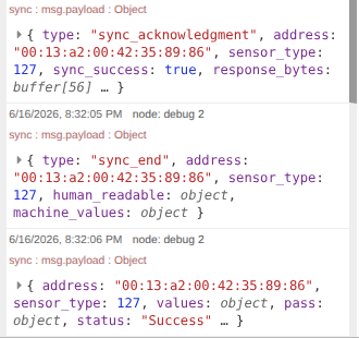
Once the sync configuration has finished, you can verify the new sensor settings by expanding the sync_end message in the debug window. There, you can review the human-readable properties to see the actual configurations applied to the sensor. In this example, the motion_threshold will now show as 400mg.
					{
  "topic": "sync",
  "payload": {
    "type": "sync_check_in",
    "address": "00:13:a2:00:42:35:89:86",
    "sensor_type": 24,
    "human_readable": {
      "core_version": 23,
      "firmware_version": 7,
      "sensor_type": 24,
      "tx_lifetime_counter": 13,
      "hardware_id": {
        "data": [ 99, 61, 0]
      },
     "network_id": "7fff",
     "destination_address": "0000ffff",
     "node_id": 0,
     "report_rate": 900,
     "output_data_rate": "100Hz",
     "motion_duration": "20msec",
     "motion_trigger_logic": "OR Mode",
     "motion_threshold": "400mg", // THIS
     "enable_axis_x": "Enabled",
     "enable_axis_y": "Enabled",
     "enable_axis_z": "Enabled",
     "full_scale_range": "±4g",
     "max_motion_tx_per_interval": 5
    },
    "machine_values": { ... }
  },
  "description" : "...",
  "packet_info": {
      "ack": 0,
      "broadcast": 0,
      "type": ""
      }
  "time": 1781217138869,
  "_msgid": "33fd88e3ea54492c"
}
Troubleshooting
Check Sensor Power
Press the CFG button on the sensor. If the TEST LED on the sensor lights up then the sensor has power. If the LED does not light up try swapping out the battery.
If the LED still doesn’t light up after changing the battery contact us for additional troubleshooting steps.
Factory Reset Sensor
If the power tests above show that power is on and the TEST LED lights up then you can attempt a factory reset. There are certain configurations that can be made to the sensor that will prevent data from being received properly such as Destination Address and Network ID. A factory reset will revert these to default settings.
- Factory Reset the Sensor
- Factory reset by pressing and release the RESET button, wait for a second, then press and hold the CONFIGURATION button, hold the CONFIGURATION button for more than 15 seconds, release CONFIGURATION button, then Wait for 3-5 seconds, finally press and release the RESET button.
- You should receive a sensor_mode message with the mode of PUM and then a second sensor_mode message with the mode of RUN
- It is recommended to have a Debug node connected directly to the Wireless Gateway node to see these messages
Multiple Gateways
If you have multiple Gateways in the vicinity of a sensor that is having issues you will need to make sure that only one Gateway is set to configure these sensors using OTF Config. Multiple OTF Configuration attempts simultaneously will cause failures during configuration.
Additionally if one Gateway is setting the Destination Address or Network ID of the sensor it will prevent the other Gateways from seeing its sensor data or being able to perform OTF Configurations to that sensor.
The recommended resolution is to make sure that only one gateway is set to configure the device. If communications are down to the intended receiver perform a factory reset of the device.
See section Hardware Mode Selection for more information on performing a factory reset.
Move Devices Closer
Its possible that there was an environmental change at the install location that is causing the Wireless range of the sensor to be reduced. To check for this it is recommended to move the sensor closer to approximately 3 feet or 1 meter from the gateway and press the RESET button to see if the sensor_mode message with the mode of RUN is received.
If it is determined that it is a range issue you can check that the antenna is fully seated. If there appears to be no issue with the antenna this can usually be resolved by adding a Repeater between the Sensor and the Receiver/Gateway running Node-Red.
If the range is limited to a few feet contact us for additional troubleshooting steps.