

Explore The Wireless Activity Detection Gen4
Device Overview
Introducing NCD’s Gen4 Industrial Wireless Activity Detector. Utilizing a wireless mesh networking architecture, this device offers an impressive wireless range of up to 2 miles. It incorporates a high-accuracy acceleration sensor that measures changes in acceleration to reliably detect mechanical movement (activity).
Upon detecting activity, the device immediately transmits a message to a remote gateway or modem, then returns to a sleep state for a pre-configured period. It makes extensive use of hardware interrupts to enter the lowest possible power state while sleeping, maximizing battery life. In addition to transmitting data when activity is detected, the sensor also sends regular “check-in” messages at set intervals. This ensures you always know the detector is online, fully operational, and actively monitoring.
Features:
- Industrial Grade Accelerometer with 3-axis for Activity Detection
- Configurable Activity Detection Parameters with Interrupts
- Configurable Acceleration Range ±2g to ±16g
- Configurable Interrupt Threshold
- Configurable Data Rate
- Configurable Interrupt Duration
- Customizable Interrupt Types with Combinations
- Wall-Mounted or Magnet
- Mounted IP65 Rated Enclosure
- 2 Mile Line-of-Sight Range with On-Board Antenna
- Superior LOS Range of up to 28 Miles with High-Gain Antennas
- Interface to Raspberry Pi, Microsoft® Azure®, Losant, and More
- Wireless Mesh Networking using DigiMesh®
- Open Communication Protocol for Easy Software Integration
- Power-Efficient Sleep Mode, Up to 10 Year Battery Life
Frame Structure
Frame Communication at Power Up
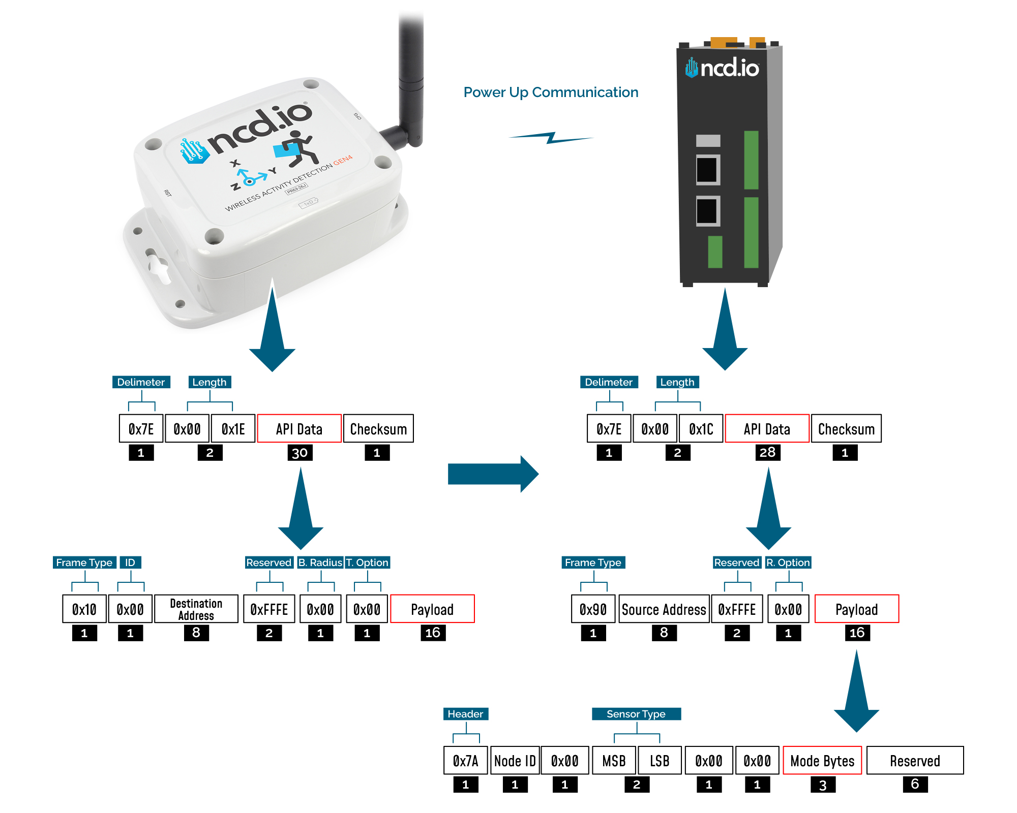
When the device powers up, depending on the mode it is going to work in, it will have a different Power Up Frame
Figure 3 provides an outline of the frame structure at Power Up, where the bytes highlighted in Red denote which mode the device has started in (Run, Configuration or Factory Default). You can look up the corresponding codes in Table 2.
If we further examine the Payload, we can use the Node ID and Sensor Type fields to determine the exact sensor that is sending the data.
A shown in the second column in Table 2, the sensor configures its PAN ID automatically depending upon the mode it is working in. During factory reset it sets the PAN ID to the value given in table therefore the factory reset frame will only be received if your Modem/Gateway PAN ID matches this ID. All 3 types of frames are shown in Figure 3, Figure 4 and Figure 5.
| Mode Type | PAN ID set by Sensor (ASCII) | Frame field | Offset (Payload section) | Value |
|---|---|---|---|---|
| Run | ID save by user / Default | Mode bytes | 7 | 0x52 |
| 8 | 0x55 | |||
| 9 | 0x4E | |||
| Configuration | 7BCD | Mode bytes | 7 | 0x50 |
| 8 | 0x47 | |||
| 9 | 0x4D | |||
| Factory Reset | 7FFF | Mode bytes | 7 | 0x50 |
| 8 | 0x55 | |||
| 9 | 0x4D |
Run Mode Frame
| Field | Number of bytes | Description |
|---|---|---|
| 7E 00 1C 90 00 13 A2 00 42 35 89 86 FF FE C2 7A 01 00 00 72 03 17 52 55 4E 00 00 00 00 00 00 79 | Example frame | |
| 0x7E | 1 | Delimiter |
| 0x001C | 2 | Length |
| 0x90 | 1 | Frame Type (Power Up) |
| 0x0013A20042536453 | 8 | Source Address |
| 0xFFFE | 2 | Reserved |
| 0xC2 | 1 | R. Option |
| 0x7A | 1 | Header with Power Up value |
| 0x00 | 1 | Node ID |
| 0x00 | 1 | Separator |
| 0x0018 | 2 | Sensor Type |
| 0x0000 | 2 | Separator |
| 0x52554E | 3 | Mode Byte for Run Mode |
| 0x000000000000 | 6 | Reserved |
| 0x79 | 1 | Checksum |
Configuration Mode Frame
| Field | Number of bytes | Description |
|---|---|---|
| 7E 00 44 90 00 13 A2 00 42 35 89 86 FF FE C2 4F00 00 19 06 00 18 00 00 05 35 63 26 00 7F FF 00 00 FF FF 00 00 00 02 58 05 00 14 00 03 20 01 01 01 01 05 5F | Example frame | |
| 0x7E | 1 | Delimiter |
| 0x0044 | 2 | Length |
| 0x90 | 1 | Frame Type |
| 0x0013A20042536453 | 8 | Source Address |
| 0xFFFE | 2 | Reserved |
| 0xC2 | 1 | R. Option |
| 4F | 1 | Header |
| 0000 | 2 | Reserved |
| 17 | 1 | Core Engine Version |
| 0B | 1 | Firmware Version |
| 007F | 2 | Sensor Type |
| 00000001 | 4 | Tx Life Counter |
| 633D00 | 3 | Hardware ID |
| 7FFF | 2 | Network ID |
| 0000FFFF | 4 | Destination Address |
| 00 | 1 | Node ID |
| 0000000A | 4 | Report Rate |
| 05 | 1 | Output Data Rate |
| 0014 | 2 | Motion Duration |
| 00 | 1 | Logic Mode |
| 0320 | 2 | Motion Threshold |
| 01 | 1 | X Axis Enabled/Disabled |
| 01 | 1 | Y Axis Enabled/Disabled |
| 01 | 1 | Z Axis Enabled/Disabled |
| 01 | 1 | Full Scale Range |
| 05 | 1 | Max Transmission Per Interval |
| 5F | 1 | Checksum |
Factory Reset Mode Frame
| Field | Number of bytes | Description |
|---|---|---|
| 7E 00 1C 90 00 13 A2 00 42 53 64 53 FF FE C2 7A 00 00 00 18 00 00 50 55 4D 00 00 00 00 00 00 D1 | Example frame | |
| 0x7E | 1 | Delimiter |
| 0x001C | 2 | Length |
| 0x90 | 1 | Frame Type |
| 0x0013A20042536453 | 8 | Source Address |
| 0xFFFE | 2 | Reserved |
| 0xC2 | 1 | R. Option |
| 0x7A | 1 | Header |
| 0x00 | 1 | Node ID |
| 0x00 | 1 | Separator |
| 0x0018 | 2 | Sensor Type |
| 0x0000 | 2 | Separator |
| 0x50554D | 3 | Mode Byte for Factory Reset Mode |
| 0x000000000000 | 6 | Reserved |
| 0xD1 | 1 | Checksum |
Sync Check In Frame
| Field | Number of bytes | Description |
|---|---|---|
| 7E 00 44 90 00 13 A2 00 42 35 89 86 FF FE C2 6F 00 00 19 06 00 18 00 00 05 35 63 26 00 7F FF 00 00 FF FF 00 00 00 02 58 05 00 14 00 03 20 01 01 01 01 053E | Example frame | |
| 0x7E | 1 | Delimiter |
| 0x001C | 2 | Length |
| 0x90 | 1 | Frame Type |
| 0x0013A20042536453 | 8 | Source Address |
| 0xFFFE | 2 | Reserved |
| 0x00 | 1 | R. Option |
| 6F | 1 | Header |
| 0000 | 2 | Reserved |
| 17 | 1 | Core Engine Version |
| 0B | 1 | Firmware Version |
| 0018 | 2 | Sensor Type |
| 00000001 | 4 | Tx Life Counter |
| 633D00 | 3 | Hardware ID |
| 7FFF | 2 | Network ID |
| 0000FFFF | 4 | Destination Address |
| 00 | 1 | Node ID |
| 0000000A | 4 | Report Rate |
| 05 | 1 | Output Data Rate |
| 0014 | 2 | Motion Duration |
| 00 | 1 | Logic Mode |
| 0320 | 2 | Motion Threshold |
| 01 | 1 | X Axis Enabled/Disabled |
| 01 | 1 | Y Axis Enabled/Disabled |
| 01 | 1 | Z Axis Enabled/Disabled |
| 01 | 1 | Full Scale Range |
| 05 | 1 | Max Transmission Per Interval |
| 3E | 1 | Checksum |
Sync Acknowledgment Frame
| Field | Number of bytes | Description |
|---|---|---|
| 7E 00 44 90 00 13 A2 00 42 35 89 86 FF FE C2 5F 00 00 19 06 00 18 00 00 05 35 63 26 00 7F FF 00 00 FF FF 00 00 00 02 58 05 00 14 00 03 20 01 01 01 01 05 D6 | Example frame | |
| 0x7E | 1 | Delimiter |
| 0x001C | 2 | Length |
| 0x90 | 1 | Frame Type |
| 0x0013A20042536453 | 8 | Source Address |
| 0xFFFE | 2 | Reserved |
| 0x00 | 1 | R. Option |
| 5F | 1 | Header |
| 0000 | 2 | Reserved |
| 17 | 1 | Core Engine Version |
| 0B | 1 | Firmware Version |
| 0018 | 2 | Sensor Type |
| 00000001 | 4 | Tx Life Counter |
| 633D00 | 3 | Hardware ID |
| 7FFF | 2 | Network ID |
| 0000FFFF | 4 | Destination Address |
| 00 | 1 | Node ID |
| 0000000A | 4 | Report Rate |
| 05 | 1 | Output Data Rate |
| 0014 | 2 | Motion Duration |
| 00 | 1 | Logic Mode |
| 0320 | 2 | Motion Threshold |
| 01 | 1 | X Axis Enabled/Disabled |
| 01 | 1 | Y Axis Enabled/Disabled |
| 01 | 1 | Z Axis Enabled/Disabled |
| 01 | 1 | Full Scale Range |
| 05 | 1 | Max Transmission Per Interval |
| 5F | 1 | Checksum |
Assertion Reason Frame
| Field | Number of bytes | Description |
|---|---|---|
| 77 00 00 00 6E 00 00 00 08 C3 61 70 70 5F 73 74 61 72 74 5F 66 6C 79 5F 74 69 6D 65 72 00 00 00 00 00 00 00 00 00 | Example frame | |
| 0x77 | 1 | Delimiter |
| 0x00 | 2 | Node ID |
| 0x0000 | 2 | Reserved |
| 0x007F | 2 | Sensor Type |
| 0x000008C3 | 4 | Line Number |
| 0x00 | Function Name |
Sensor Data Frame
| Frame Field | Offset (Payload section) | Fixed Value (if any) | Length | Description |
|---|---|---|---|---|
| Header | 0 | 0x7F | 1 | Header to differentiate various types of packets |
| Node ID | 1 | 0x00 | 1 | Node ID to differentiate up to 256 nodes in a network. User configurable values |
| Firmware | 2 | 0x01 | 1 | Used to determine firmware version programmed in the device |
| Battery Voltage | MSB 3 | 0x03 | 2 | Battery Voltage = 0.00322*(03*FF+FE) |
| LSB 4 | 0xFE | Battery Voltage = ((Battery Voltage MSB x 256) + Battery Voltage LSB) x 0.00322 V | ||
| Packet Counter | 5 | - | 1 | It is an 8-bit counter that increments with each packet transmission. It can be used to detect missing packets |
| Sensor Type | MSB 6 | 0x00 | 2 | Two bytes to determine sensor type. It can be used in conjunction with Node ID to create sensor networks of up to 256 nodes for a single type of sensor and multiple such networks can coexist and can be differentiated in processing software on PC end. |
| LSB 7 | 0x18 | Sensor Type 24 | ||
| Error/Reserved byte | 8 | 0x00 | 1 | Bit 7: Reserved Bit 6: Reserved Bit 5: Reserved Bit 4: Reserved Bit 3: Reserved Bit 2: Transmission Type Bit 1: Status Bit 0: Reserved |
| Acceleration X Axis | 9/ Data[0] | |||
| 10/ Data[1] | - | |||
| 11/ Data[2] | - | |||
| 12/ Data[3] | - | 4 | X Axis = Data[0] << 24 | Data[1] << 16 | << Data[2] << 8 | Data[3] | |
| Acceleration Y Axis | 13/ Data[0] | |||
| 14/ Data[1] | - | |||
| 15/ Data[2] | - | |||
| 16/ Data[3] | - | 4 | Y Axis = Data[0] << 24 | Data[1] << 16 | << Data[2] << 8 | Data[3] | |
| Acceleration Z Axis | 17/ Data[0] | |||
| 18/ Data[1] | - | |||
| 19/ Data[2] | - | |||
| 20/ Data[3] | - | 4 | Z Axis = Data[0] << 24 | Data[1] << 16 | << Data[2] << 8 | Data[3] |
Configuration Mode
To put an NCD.io wireless sensor into manual configuration mode, you can do the following:
Using Buttons
1. Press and release the RESET button
2. Immediately press and hold the CONFIGURATION button
3. Hold the CONFIGURATION button for about 5–8 seconds
4. Release the CONFIGURATION button
Using Magnetic
1. Bring the magnet into close proximity to the designated RESET point on the device housing, then remove it immediately.
2. Immediately place the magnet against the designated CONFIGURATION activation point on the device housing and hold it in place.
3. Maintain the magnet’s position at the CONFIGURATION point for approximately 5 to 8 seconds.
4. Remove the magnet from the CONFIGURATION position.
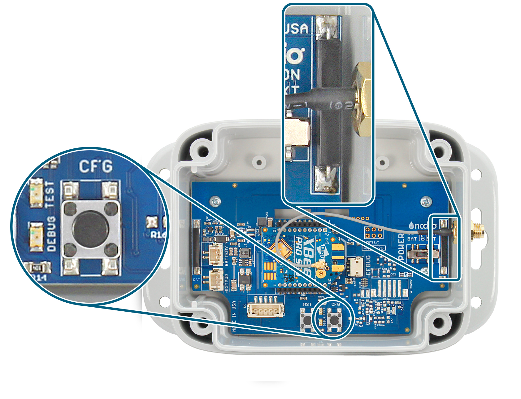
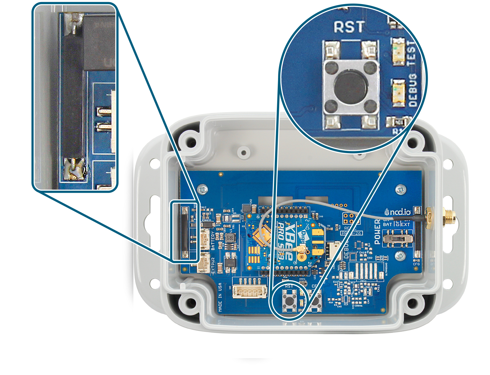
In configuration mode, the device sets its X-bee pan id to 7BCD. Also, the destination address used by the sensor is extracted from the incoming packet (source address). This ensures that once you put a device in configuration mode you just need to change the PAN ID you are sending to in your Modem/Gateway to match with the sensor and start configuring your device.
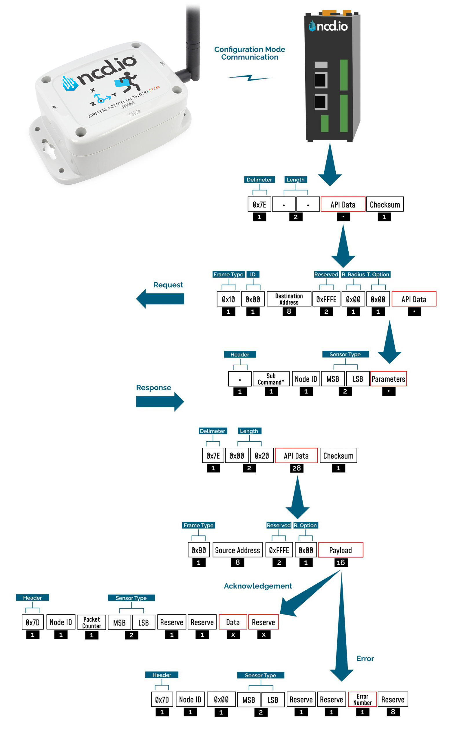
A standard configuration packet and its fields are explained in Figure 5. Its possible responses are also shown. The complete set of commands supported by this sensor are shown in тхе Appendix, these can be used in the Parameters field of the Payload section. The sensor responds to these commands with an acknowledgement if the process completed successfully or with an error if it failed to setup a parameter. The respective Data and Reserve section length and values are shown in Table 6 for the case of acknowledgement. In the case of error, the reserved section will be fixed and not used, while the Error number byte will determine the type of error returned. These errors are in a separate section in the Appendix.
Sync Config Mode
This specific device also supports SYNC mode, which allows you to configure the sensor without needing physical access to it (no need to press buttons or trigger a magnetic switch).
By default, the device automatically enters SYNC mode every hour and transmits a SYNC packet (described below). This packet serves two main purposes:
Current Settings: It includes all the active settings, allowing you to easily verify or read the sensor’s current configuration.
Configuration Window: It signals that the sensor is temporarily in configuration mode. During this brief time window, you can transmit a Master Command to update the settings.
Once the time window closes, the device automatically returns to its normal operation (Run mode).
Example Configuration Command
The following is an example on how to read and change some of the parameters that affect the operation of the NCD Sensor.
Master Command
The Master Command is a comprehensive command that allows you to configure all of the device’s settings in a single transmission.
Below, you will find the structure of the master command, along with a detailed payload description for each byte.
					7E 00 38 10 01 00 00 00 00 00 00 FF FF FF FE 00 00 6C 00 00 7F FF 00 00 FF FF 00 00
00 01 2C 07 00 19 01 07 44 01 01 00 03 0A C9
Complete Payload
6C 00 00 7F FF 00 00 FF FF 00 00 00 01 2C 07 00 19 01 07 44 01 01 00 03 0A
Master Command Payload Description
| Index | Byte | Size (bytes) | Setting | Valid Options | Description |
|---|---|---|---|---|---|
| [0] | 6C | 1 | Header | ||
| [1:2] | 00 00 | 2 | Reserved | ||
| [3:4] | 7F FF | 2 | Network ID | 0x00 -- 0x7FFF | Network ID Valid Range: 0-0x7FFF. |
| [5:8] | 00 00 FF FF | 4 | Destination Address | Default value: 0000FFFF for Broadcast Mode Example of targeted address: 41D5EC37 | Sets the Destination Address of the sensor. The sensor will send Run mode Data packets to this Address |
| [9] | 00 | 1 | Node ID | 0x00 -- 0xFF | Sets the Device node ID and Data Transmission Interval. The node id value can go from 0-255 and The Data transmission value can go from 3-0xFFFFFF Seconds |
| [10] | 0E | 1 | Output Data Rate | 0x01--1Hz 0x02--10Hz 0x03--25Hz 0x04--50Hz 0x05--100Hz (Default) 0x06--200Hz 0x07--400Hz | This would determine how many samples the output data has, which is directly related to the highest frequency components that can be measured. |
| [11:12] | 001A | 2 | Motion Duration | Valid Range: 0x01 -- 0xFFFF | Sets the minimum amount of time in milliseconds that motion/impact must continuously persist before triggering an alert. This filters out single, brief vibrations or random background noise from causing false alarms. |
| [13] | 01 | 1 | Motion Trigger Logic | 0x00: OR(default) 0x01: AND | This setting determins how the sensor handles the X, Y, and Z axes to trigger an immediate sensor data transmission (motion). It allows you to choose whether a single axis or a combination of axes must cross your safety threshold before sending a Motion message. |
| [14:15] | 000A | 2 | Motion Threshold | Valid Range: 0x01 -- 0x5C46 | Set a motion detection threshold for the sensor to trigger a data transmission. This is an interrupt-based configuration. |
| [16] | 01 | 1 | Enable or Disable X axis | 0x00: Disable 0x01: Enable | |
| [17] | 01 | 1 | Enable or Disable Y axis | 0x00: Disable 0x01: Enable | |
| [18] | 01 | 1 | Enable or Disable Z axis | 0x00: Disable 0x01: Enable | |
| [19] | 01 | 1 | Full Scale Range | 0x00: +- 2g(default) 0x01: +- 4g 0x02: +- 8g 0x03: +- 16g | Set how large of a range the device can measure acceleration in. |
| [20] | 01 | 1 | Max Motion Tx Per Interval | Valid Range: 0x01 -- 0x1E | Set Number of times device will transmit a motion data message due to motion triggers per interval. |
Read Sensor Settings
Sync
By using the SYNC packet, you can easily check the current settings configured on your sensor. The SYNC message includes the exact bytes that correspond to your active configuration values (you can find an example of a SYNC packet at the beginning of this document).
If you ever need to manually trigger a SYNC message, simply press the reset button. When you do this, the sensor will respond by sending a quick sequence of three messages: RUN, followed by sensor_data, and finally SYNC.
Additionally, the sensor will automatically transmit a SYNC message every hour by default to keep everything updated.
Read Wireless Sensor Transmission Power Level
This Command may be used to read the wireless radio transmission power. This value will indicate how much RF power the radio is emitting. The higher the value, the higher the radiated wireless power, resulting in a longer range and decreased battery life (please note that all battery ratings are shown at maximum wireless transmission power). Lower values are desirable in application that may benefit from greatly improve battery life, especially when high power data transmissions are not required.
Read Sensor Power Command:
7E 00 13 10 00 00 00 00 00 00 00 FF FF FF FE 00 00 F7 16 00 00 00 E7
Sensor will respond with the Power Level value:
7E 00 1C 90 00 13 A2 00 41 91 1B 83 FF FE C1 7C 00 09 00 0E 00 00 04 00 00 00 00 00 00 00 00 F5
From the above command, the following data may be extracted:
A. Sensor MAC Address
00 13 A2 00 41 91 1B 83
B. Sensor Payload
7C 00 09 00 0E 00 00 04 00 00 00 00 00 00 00 00
C. Power Level
0x04 (data byte 23)
The sensor will respond with a value from 0x00 to 0x04. The default value is 0x04, allowing for the greatest possible transmission range and the shortest battery life.
Read Wireless Sensor Retries
The following command may be used to read the number of retires. The number of retries is one of the most useful settings for NCD wireless sensors.
Lets say the number of retires is set to 5. In a normal case, the sensor will wake up, gather data, send data to the modem, and go back to sleep. But due to some environmental issues (lets say a few trucks were driving by and they came in between the sensor and the modem) the modem didn’t receive the data. In that case, the sensor will try 4 more times to send the data. If the modem still doesn’t get the data after all 5 tries, the sensor will quite trying and will go back to sleep. The Machine Uptime sensor will wake up after the predefined sleep time and will try again.
The highest number of retries allowed is 10.
Read The number of Sensor Retries:
7E 00 13 10 00 00 00 00 00 00 00 FF FF FF FE 00 00 F7 17 00 00 00 E6
Sensor will respond with the Retries value:
7E 00 1C 90 00 13 A2 00 41 91 1B 83 FF FE C1 7C 00 1B 00 0E 00 00 0A 00 00 00 00 00 00 00 00 DD
From the above command, the following data may be extracted:
A. Sensor MAC Address
00 13 A2 00 41 91 1B 83
B. Complete Sensor Payload
7C 00 1B 00 0E 00 00 0A 00 00 00 00 00 00 00 00
C. Retries Number
0x0A (data byte 23)
Error Code Descriptions
Here a summary is provided of what the different error codes mean (in case a valid Ack has not been received).
| Error Number | Description |
|---|---|
| 0x01 | Invalid command |
| 0x02 | Sensor Type mismatch |
| 0x03 | Node ID mismatch |
| 0x04 | Apply change command failed during X-bee parameter update |
| 0x05 | Invalid API packet command response received after Apply change command |
| 0x06 | Write command failed during X-bee parameter update |
| 0x07 | Invalid API packet command response received after Write command |
| 0x08 | Parameter change command failed during X-bee parameter update |
| 0x09 | Invalid Parameter change command response packet received after Write command |
| 0x0A | Invalid/Incomplete packet received |
| 0x0F | Invalid parameter for setup/saving |
Frame Checksum Calculation
In order to successfully communicate over the API protocol, the checksum is of vital importance. The X-bee at either end of the link will reject packets if the checksum does not match.
Calculation for transmission
For sending packets, the checksum calculation works as follows:
1. Not including the frame delimiter and length, add all the bytes and keep the lower 8 bits of result
2. Subtract this value from 0xFF (hex)
3. The resultant value is the checksum
4. Append this byte to the original packet for sending
Consider the example for the command Set Broadcast shown in APPENDIX A and see that the calculated checksum matches with the checksum sent by the terminal/LabVIEW. Let us break the example command below:
7E00 1310 0000 0000 0000 00FF FFFF FE00 00F7 0100 0001 FB
If we extract the relevant bytes from the command we get:
10 0000 0000 0000 00FF FFFF FE00 00F7 0100 0001
Adding the bytes and taking the last 8 bits yields:
0x04
Substract the value obtained (0x04) from 0xFF
0xFF-0x04=0xFB
We get a value matching the one in the packet checksum field.
Calculation for reception
Although checksum is matched by the X-bee itself, but for understanding follow these steps to match checksum at reception
1. Not including the frame delimiter and length, add all the bytes including the received checksum
2. Keep only the last 8 bits
3. If the result is 0xFF, the checksum is correct and the packet can be processed.
Consider the example for the command Set Broadcast shown in APPENDIX A and see that the received packet checksum verifies since the result is 0xFF.
7E00 1C90 1310 A200 4158 1CCB FFFE C17C 000D 0001 0000 FF00 0000 0000 0000 00F3
If we extract the relevant bytes from the command we get:
90 1310 A200 4158 1CCB FFFE C17C 000D 0001 0000 FF00 0000 0000 0000 00F3
Adding the bytes and taking the last 8 bits yields:
0xFF