This module is no longer sold by NCD and this guide is here for existing applications that use it. For the replacement module and links to the documentation for it see the product “WiFi Communications Module with Bluetooth USB MQTT“
WiFi Communications Module
Our WiFi communications module make it easy to connect your office or home network to the entire range of NCD Industrial controllers. WiFi 802.11 b/g protocols are supported with this interface module, allowing transparent serial communication between your smart phone, tablet, or PC using TCP/IP communications. With a complete gamut of security protocols, our WiFi communication modules provide excellent security and reliability. The WiFi communication module fits NCD.io ProXR, ProXR Lite, Fusion, Taralist, and many other controllers, allowing any of our socketed devices to use WiFi wireless communications. This devices is available with a external antenna for installation in metal enclosures or without for a more compact profile. Our module is based on the Roving Networks (now Microchip.com) RN171 WiFly WiFi interface processor.
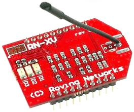
WiFi_INT with Integrated Antenna
The WiFi_INT is available with a Integrated Antenna for low-profile installation applications. You can expect reliable operation up to a maximum of 320′ line-of-site using the integrated antenna.
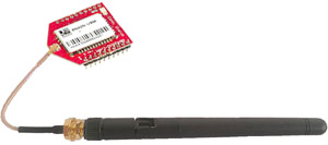
WiFi_EXT with External Antenna
The WiFi_EXT is available with a external antenna for applications that require a antenna to be mounted outside the enclosure. The external antenna does not improve range, but it does allow for operation inside metal enclosures by externally mounting the antenna. The external antenna is connected to the module using a U.FL to RP-SMA adapter.
Specifications
| WiFi Communications | IEEE 802.11 b/g |
| FCC Certified | Yes |
| ASCII Interface | Yes |
| Memory Type | Flash |
| GPIO | 14 |
| DHCP Support | Yes |
| Statip IP Support | Yes |
| Password Protection | Yes |
| Frequency Range | 2.405-2.48GHz |
| Package Type | Socket module |
| Package Size | 24.4 x 29.9 mm |
| Min Temp Range | -40C |
| Max Temp Range | 85C |
| Op Voltage Min | 3.0V |
| Op Voltage Max | 3.6V |
| Power Consumption TX | Up to 120ma at 3.3VDC |
| Power Consumption RX | Up to 40ma at 3.3VDC |
| Communication Speed 802.11b | 1-11 Mbps |
| Communication Speed 802.11g | 6-54 Mbps |
| RoHS Compliance | Yes |
| Production Status | In Production |
Range Testing
We encourage our customers to take a smart phone to the installation location of this module and examine the WiFi signal strength. This will give an approximation of signal strength you can expect when using this module.
Features
- Direct internet connectivity provides internet access to every node
- Point to point connectivity to every node without the need for custom profiles
- Based on common 802.15.4 footprint
- 3 Antenna options available – wire, reverse polarity SMA connector, and U.FL connector
- Ultra low power: 4µA sleep mode, 38mA active
- On-board TCP/IP stack includes DHCP, UDP, DNS, ARP, ICMP, HTTP client, FTP client and TCP
- Firmware configurable transmit power: 0dBm to 12dBm
- Hardware interfaces: TTL UART
- Host data rate up to 464Kbps over UART
- Supports Adhoc and infrastructure networking
- 8 general purpose digital I/O
- 3 analog sensor inputs
- Real-time clock for time-stamping, auto-sleep, and auto-wakeup modes
- Accepts 3.3VDC regulated power supply
- Configuration over UART or wireless interface (via Telnet) using simple ASCII commands
- Over the air firmware upgrade (FTP)
- Secure Wi-Fi authentication: WEP, WPA-TKIP , WPA2-AES
This guide will help you understand advanced usage of the WiFi interface module.
This guide provides you with a complete command set for usage and configuration using serial communication.
From the Manufacturer
The RN171XV module is a certified Wi-Fi solution especially designed for customers who want to migrate their existing 802.15.4 architecture to a standard TCP/IP based platform without redesigning their existing hardware. The RN171XV module is based upon Microchip’s robust RN171 Wi-Fi module and incorporates an 802.11 b/g radio, 32 bit processor, TCP/IP stack, real-time clock, crypto accelerator, power management unit and analog sensor interface. The RN171XV module supports infrastructure networking for worldwide internet access directly by every node and adhoc connectivity for fully connected point to point networks, unlike many 802.15.4 implementations that need extensive, custom application profiles and additional bridging products. The RN171XV supports industrial temperature ranges, making it ideal for applications such as sensor networks, industrial or commercial controllers, utility meters, and M2M applications.
Usage & Electrical Specfications:
The WiFly WiFi module is designed to operate at 3.3VDC powered by NCD.io devices equipped with a communication module socket. The WiFly is typically used in combination with NCD devices, though it may be compatible with select select 3rd party hardware. To use this device, simply follow the instructions below. Optional accessories will be required for initial configuration and connection to your WiFi network.
Setup and Instructions
Step 1:
Remove the WiFly communications module from your NCD controller and plug it into a ZIGMO adapter. The ZIGMO adapter is used to configure the WiFly module using the USB port of your computer.
Step 2:
Download and install our Base Station Software (ncd.io/start). Base Station will be used to configure the WiFly module, as we have developed a customer interface to help simplify this process. Base Station is designed for Windows 8/10, and has not been tested with other versions of Windows. Base Station will require the latest .Net framework, so make sure your computer is up to date prior to use.
Step 3:
Run Base Station and Choose a COM port. If a COM port does not appear, make sure the USB LED is illuminated on the ZIGMO adapter. If the light is off, please visit FTDIChip.com and install the latest drivers for the FT232RL. Most versions of windows included these drivers, so it should never be necessary to install them separately.
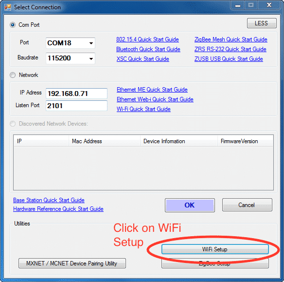
Make Sure the Baud Rate is Set to 115.2K Baud. Click the “MORE” button n the upper left corner of the window. The word “MORE” will change to “LESS” as shown in the window below. This will open extended options for configuring the WiFly module.
Step 4:
Click the WiFi Setup button as shown above.
Step 5:
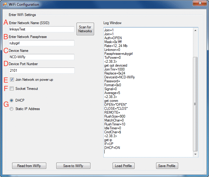
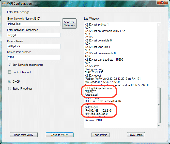
A new window will open named “Wi-Fi Configuration”. Wait for the progress bar to finish loading. There will be several options to set up the configuration for your module.
- Enter Network Name (SSID): Your Wi-Fi module will already have a network name stored. This is the router to which it was connected for testing. This is where you will enter the information for your network. NETWORK SSID MUCH BE ENTERED WITH NO SPACES. If you do not know this information, you can select “Scan for Networks” to the right for the “Enter Network Name” text box. This will show all Wi-Fi networks that are in range of your module. Choose the appropriate network and click “Select”. This process will fill in the Network Name for you.
- Enter the Network Passphrase: This will be the password that allows access to your wireless router.
- Device Name: Makes the device easier to find on your network. This name can be whatever you choose.
- Device Port Number. By default this is set to 2101. This is the number that is most commonly used and is recommended, however, it can be set to any value.
- Join Network on power up: It is recommended that you leave this option checked. “Join Network on power up” means that as soon as the module powers up it attaches to the network. This pick chip on the relay board your module will later be installed into has no way to command the Wi-Fi module to connect so checking this option will allow automatic connection.
- Socket timeout: By default this box is unchecked. When using a mobile device, it is recommended to check this box.
- DHCP or Static IP Address: By default the module is set for DHCP which in most cases is the recommended setting. This means that your module will obtain an IP address from the router.
If you are using the Wi-Fi module on a network switch or you do not have a DHCP Server, choose Static IP Address option instead.
You can then enter the IP address and other information into the boxes that appear:
- Static IP Address
- Default Gateway
- Subnet Mask.
- This device will then always try to use the IP Address
- Make sure that the IP Address is reserved on the network so no other devices may obtain that address.
- When all setting changes are complete, click “Save WiFly” button. This will write all settings into the module. A progress bar will indicate the completion of the configuration.
- Caution: Be careful when storing this information. If this information is stored incorrectly, you will need to install the module back into your modem and reconfigure the module.
- When storing is complete, you will see the words “READY” and “Associated!”. Further down, you will also see the device’s IP Address. If using DHCP, you might want to write this down. When you place the module into the Relay board from the Configuration board, you will need to know the module’s IP Address.
- Close Software
- Install Module into a Relay Board
Disconnect the USB cable from the Configuration Board. Disconnect Wi-Fi module from the Configuration Board. Install the Wi-Fi module into a Relay Board. - Connect Power Supply to the Wi-Fi Module. The LED should light on the Wi-Fi Module as soon as power is supplied. Eventually the green LED light on the Wi-Fi Module should be flashing slowly. This indicated a good connection to the router.
Testing WiFi Communications
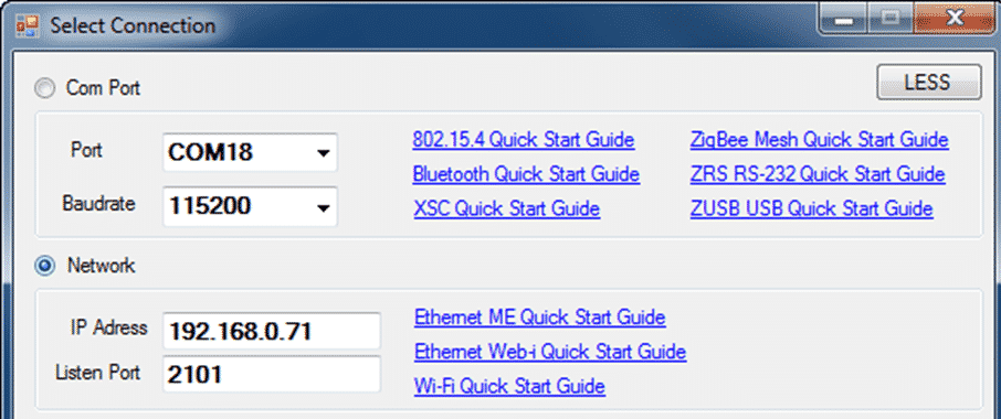
- Run Base Station software.
- On the ‘Select Connection’ window, click ‘Network’
- Enter IP Address
- Port Number- 2101
- Click “Okay”
- Base Station should connect to your controller and provide you with a menu of options.
Troubleshooting
These instructions are for those who had problems on Step 2.
Installing USB Drivers
If you connect the USB cable to the Wi-Fi Module Configuration Board and the USB light does not illuminate, you will need to install drivers in order to mount the board to your computer as a virtual COM Port. Please visit: http://www.ftdichip.com/Drivers/VCP.htm.
Unable to Connect to your Network
If you are unable to connect to your network, make sure there are no spaces in your network name.
Please change the name of your network to eliminate spaces.