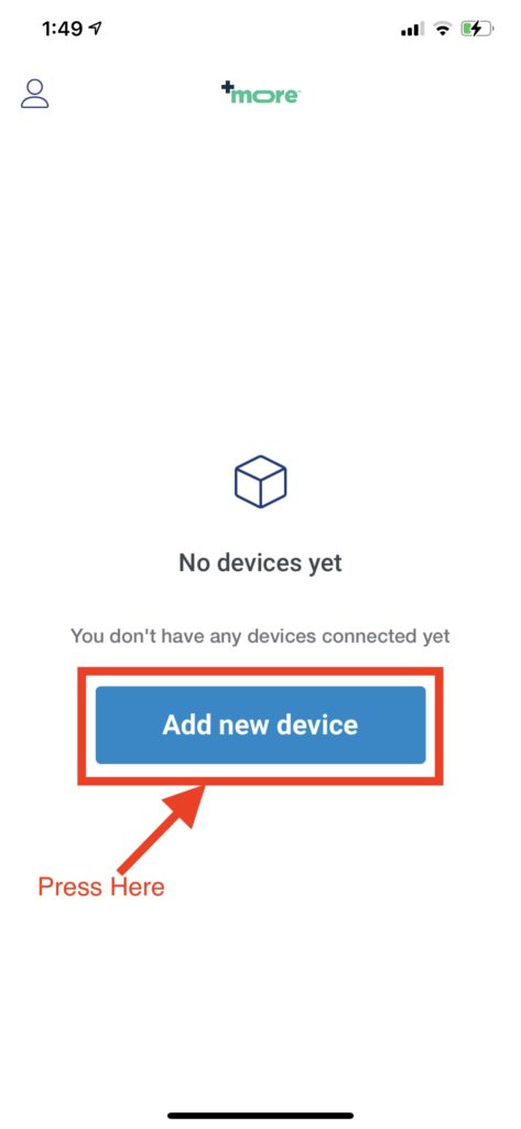
After opening the App for the first time you will see this screen. Click the Add new device button.
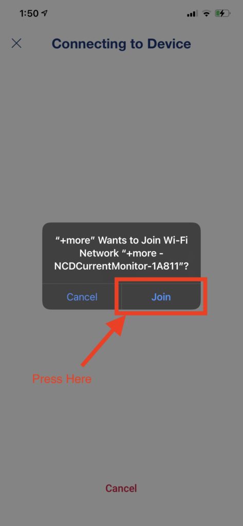
Connecting to the Sensor
You will now be prompted to connect to the sensor via WiFi if the phone is within range of a sensor that is in setup mode(flashing Blue LED).
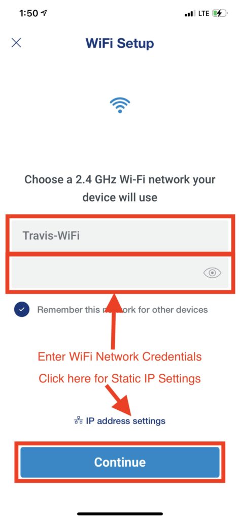
Configure WiFi
Once the App connects to the board you will be prompted to enter WiFi network credentials for the WiFi network you want the sensor to connect to. Optionally you may also press IP address settings to enter Static IP address credentials.
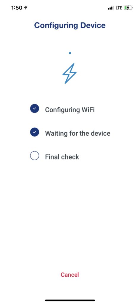
Wait for Device Configuration
This screen will be displayed while the sensor connects to the WiFi network and then to the +More cloud server. Your phone should also automatically disconnect from the sensor’s WiFi connection once this is successful and reconnect to the internet via Cellular or WiFi.
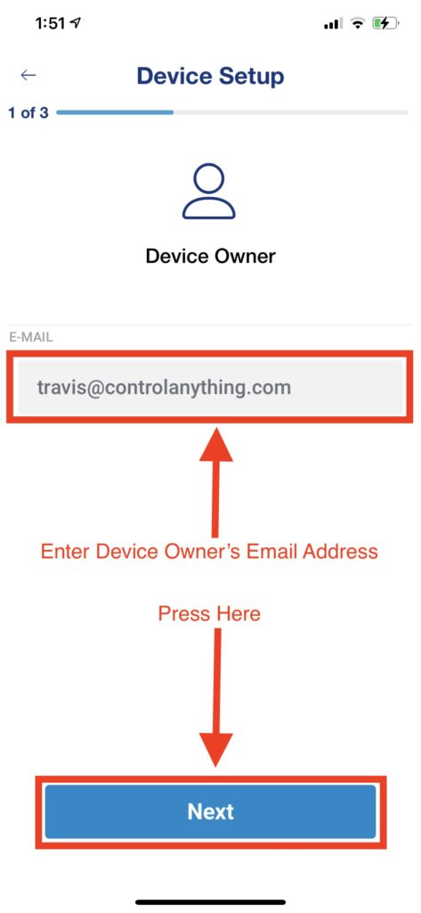
Owner Email
You will now be prompted to enter the email address for the user who owns the sensor.
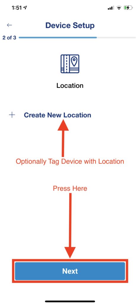
Location Tagging
This Screen allows you to optionally tag the device with a location. This can be useful if you have multiple sensors in different geological location.
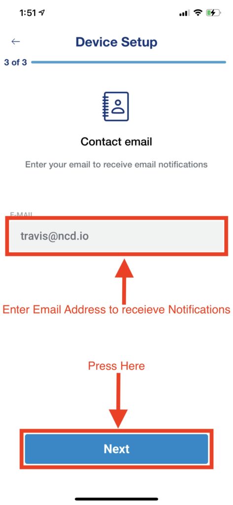
Notification Email
This screen allows you to enter the email address which notifications would be sent to. These notifications can prompt the user, for instance, that a sensor reading has crossed a threshold.
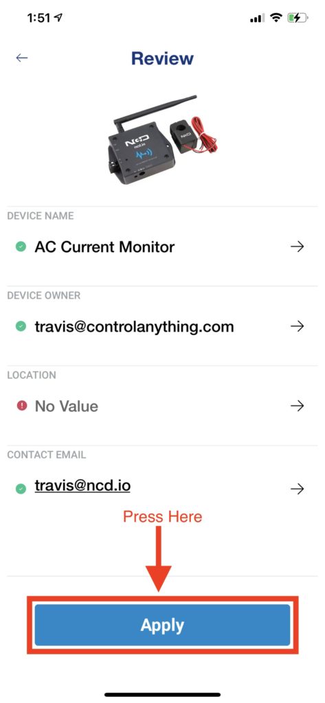
Settings Review
This Screen displays a summary of the settings entered during the setup of the sensor.
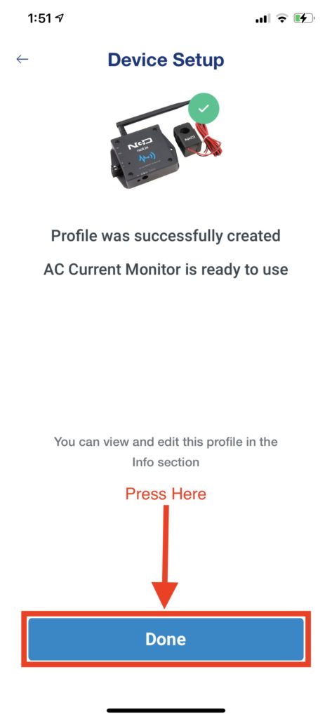
Setup Complete
This Screen prompts the user that the setup of the new sensor was successful and that the device is now ready to use.
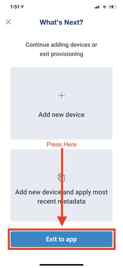
Next Steps
This Screen allows the user to exit to the app or add another device.
Exploring the User Interface
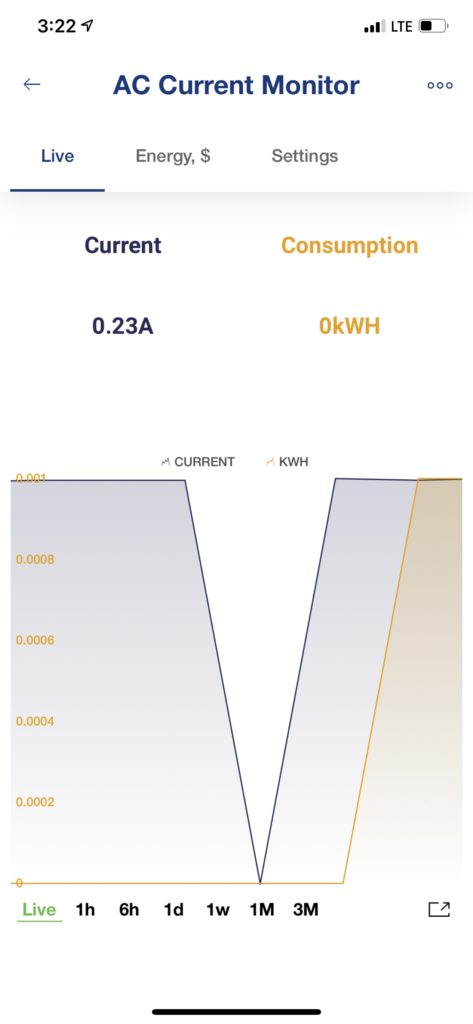
Live Current/kWH Monitoring UI
At this point you may be taken to the Sensor’s UI or you may be taken to the device list UI. If you are taken to the Device List UI then click on the newly added sensor to begin monitoring information.
The Live view shown here shows the current Circuit amperage consumption and the kWH consumption. kWH readings will not be accurate until the circuit voltage is entered under the Settings Screen.
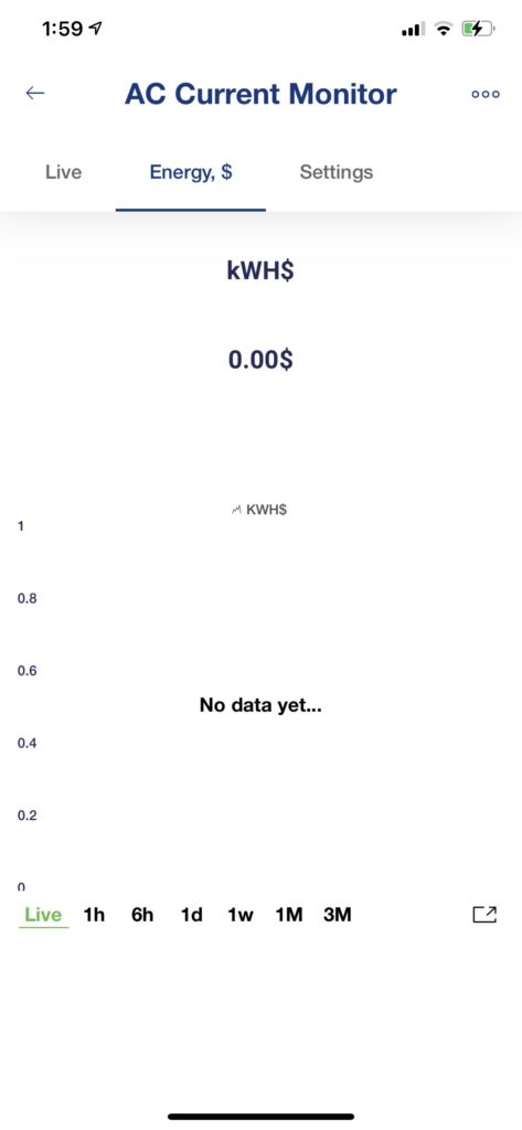
Energy Monitoring UI
The Energy,$ UI allows the user to monitor circuit cost. This could be useful to determine how much your HVAC costs in a month or how much it costs to operate any other equipment.
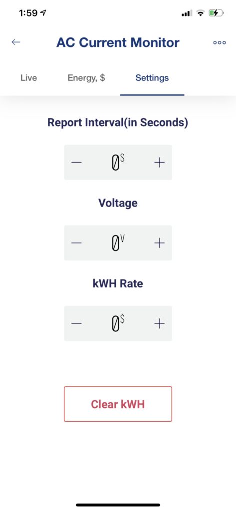
Settings UI
The Settings UI will allow the user to configure various settings on the sensor.
Report Interval is the interval in seconds at which the sensor will report it’s telemetry information(In this case Current, kWH, and kWH$.
Voltage allows the user to configure the voltage of the circuit being monitored(110V, 120V, 220V, 240V, etc). This setting must be configured in order to get accurate kWH and kWH$ readings.
kWH Rate is the rate at which your power utility charges for 1 kWH of electricity. This setting must be configured in order to get accurate kWH$ readings. If your utility provider varies this cost based on Peak/off Peak hours it is possible to alter this rate at different times of day using +More’s automation feature which is covered in the Automation section.
Clear kWH allows the user to clear the current kWH total and will also clear the kWH$ variable. It is possible to trigger this via Automation as well.
Automation
Create a New Automation
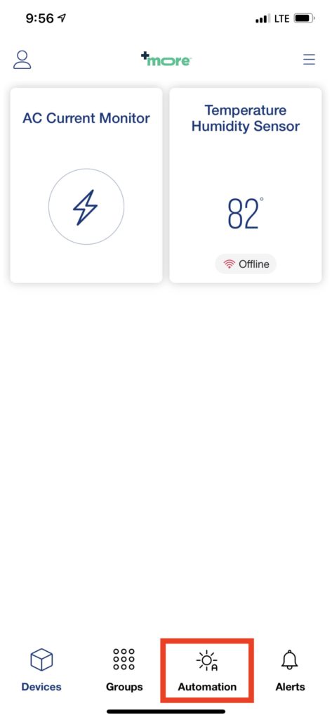
To Create a new Automation go to the Devices List UI and click on the Automation button at the bottom of the screen.
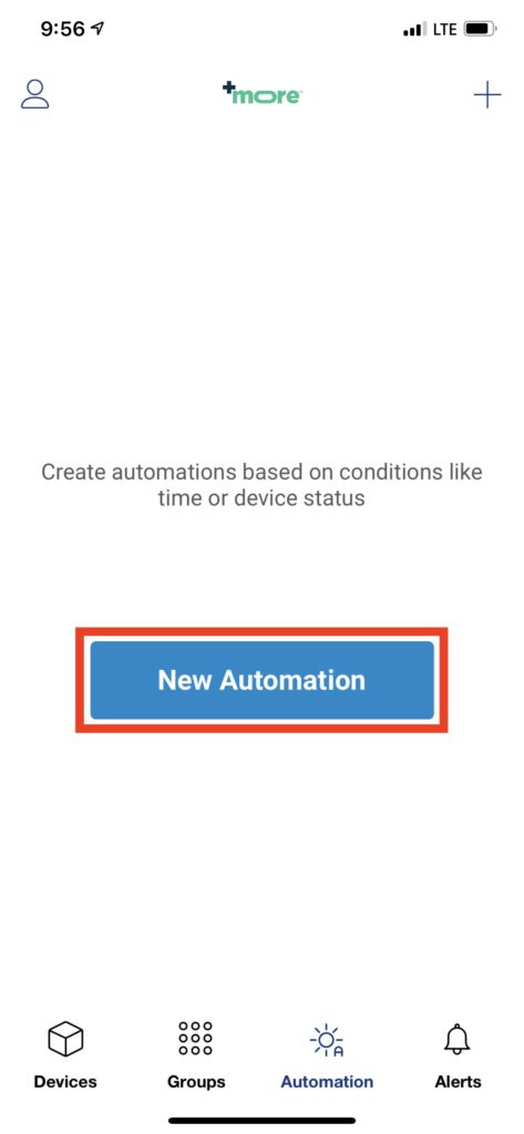
New Automation
Click the New Automation Button
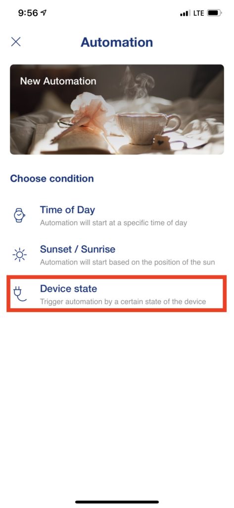
Choose Condition
The Automation being created must be triggered by a Condition. In this example we will choose Device State as the trigger condition.
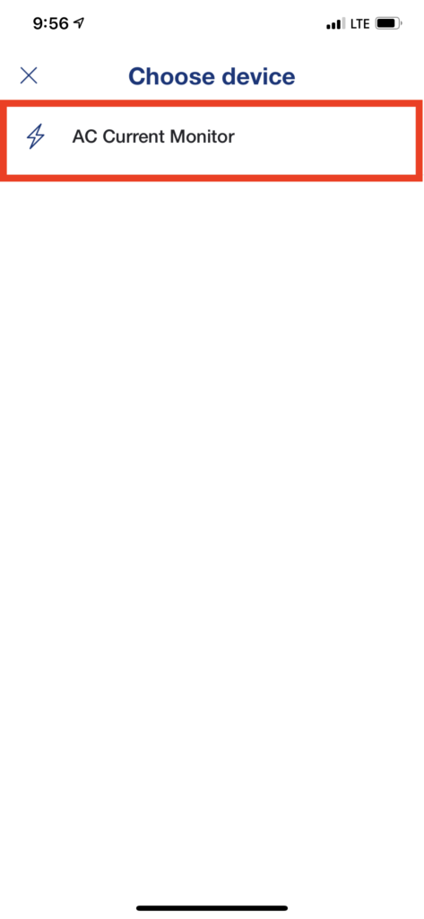
Triggering Device
We now select the device from which we want to monitor a state condition from. In this example it will be the AC Current Monitor.
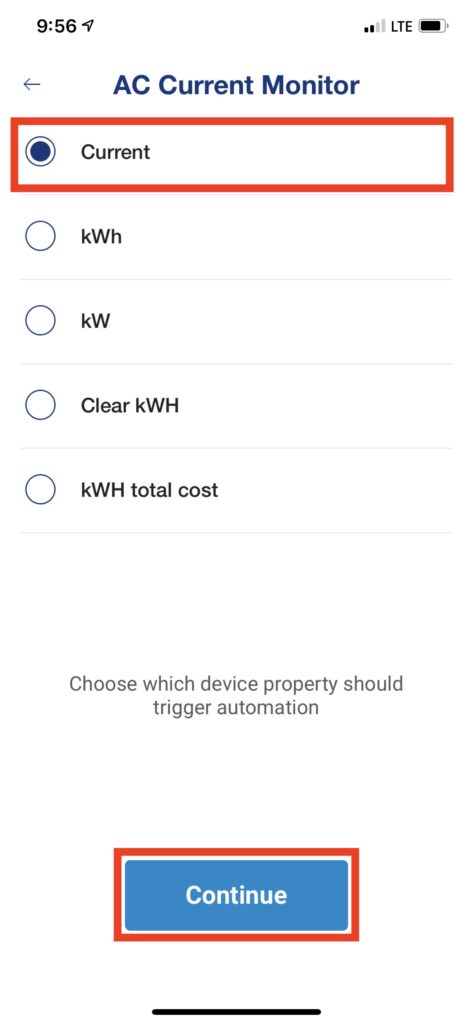
Choose Device Variable to Monitor
Now choose the device variable which to monitor. In this case we will monitor the current consumption variable to determine if a light is on or off.
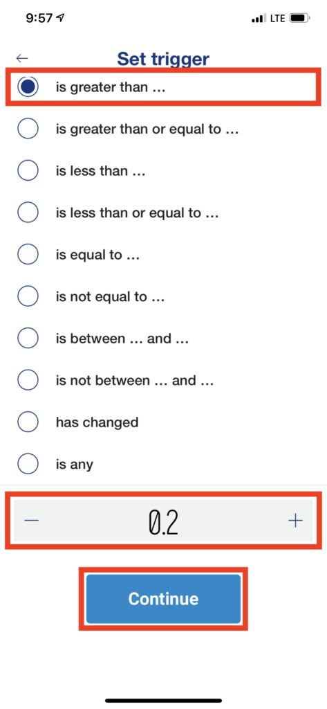
Variable State Condition
Now we may select a threshold value for the Current variable. We will trigger this automation when the Current reading is greater than 0.2 amps which indicates the light is on.
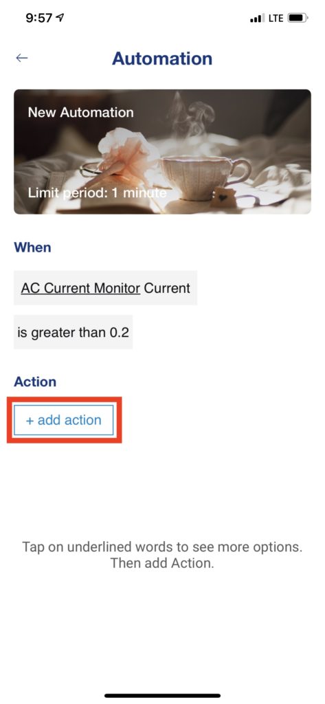
Add Action
Next we will add an action to perform when the condition we just configured is met or exceeded. Note: multiple actions can be added to an automation such as triggering a notification and email.
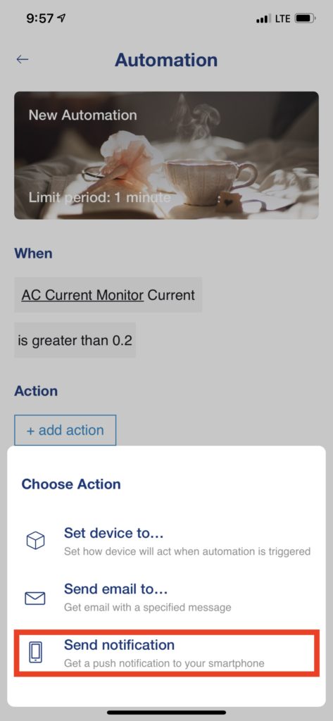
Select Automation Action to Perform
Next you can select the action to perform when the condition state is met or exceeded. In our example we will trigger a native notification on our mobile device.
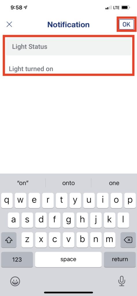
Notification Subject and Message
Next we will enter the Subject and message to be displayed in the notification when this automation is triggered.
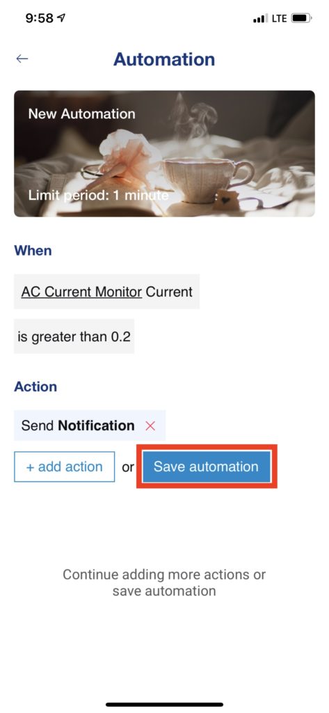
Save or Add More Actions
Review your automation here. Once satisfied you may either add additional Actions or Save the Automation.
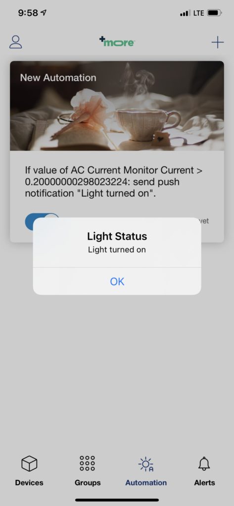
Test the Automation
I will now turn the light on to test the automation. If everything is configured correctly then a notification will be displayed on the screen. If OS settings on the mobile device are configured correctly these notifications will appear similar to the way notifications are sent for new text messages.