GPIO in minutes
If you haven’t already, make sure to go through the setup tutorial. Once you’ve finished that we’re ready to go! The PCA9536 is an 8-pin CMOS device that provides 4 bits of General Purpose parallel Input/Output (GPIO) expansion through the I2C bus. We manufacture multiple mini-modules that utilize this chip, you can check them out here.
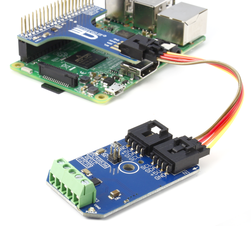
If you haven’t already, get your devices plugged in, on a Raspberry Pi, that means installing the adapter, hooking up the I2C cable to the In port on the Relay Board, and powering the board. On any platform without native I2C, we’re going to assume you have a USB to I2C Adapter, which should also be connected to the PCA9536.
Now that you’re plugged in, let’s get this party started!
We are constantly working to improve our software libraries, as such, some of the screen shots in these articles may not reflect the latest functionality of the node. Please make sure to check out the "Info" tab on the node for the most up to date information.

Install the library
To make your life easier, we’ve build a library for the PCA9536 that provides a node-red node. This should prevent you from needing to muck about in the data sheet to find the appropriate I2C commands. You can use NPM to install this library from within your node-red directory (usually ~/.node-red):
npm install --unsafe-perm ncd-red-pca9536
You can try this command without the --unsafe-perm flag, it is there to allow nodeJS to access your hardware devices, it may not be necessary on all setups, but won’t hurt anything in any case.
Once this is done, spin up your node-red instance and you should see a node in the palette called ncd mcp23008. Drag this on over to the dashboard, and double click to open the configuration form.
ALL of our ncd-red-* libraries are functional without node-red as well. Check out the 'test.js' file to see example usage for vanilla NodeJS development.
Configure the Node
I2C Connection
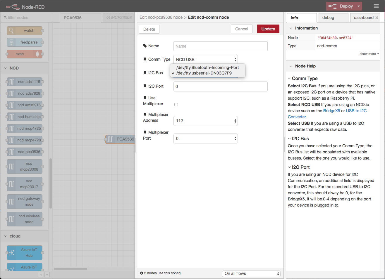
Once you’ve opened the configuration panel, you’ll need to set up the I2C connection, click on the pencil icon next to that field, and you’ll be presented with some simple options.
If you are using a native I2C port, select I2C Bus from the Comm Type drop down, this will pull in a list of active I2C Busses available on your device.
If you are using the USB to I2C adapter, select NCD USB, and select your USB device from the I2C Bus list. The I2C Port field should stay at 0, unless you are using a BridgeX5, in which case it should reflect the I2C Port you are using on that device.
Once that’s done, click Add at the top of the form to save your connection configuration, this will automatically attach it to your new PCA9536 node.
PCA9536 Setup
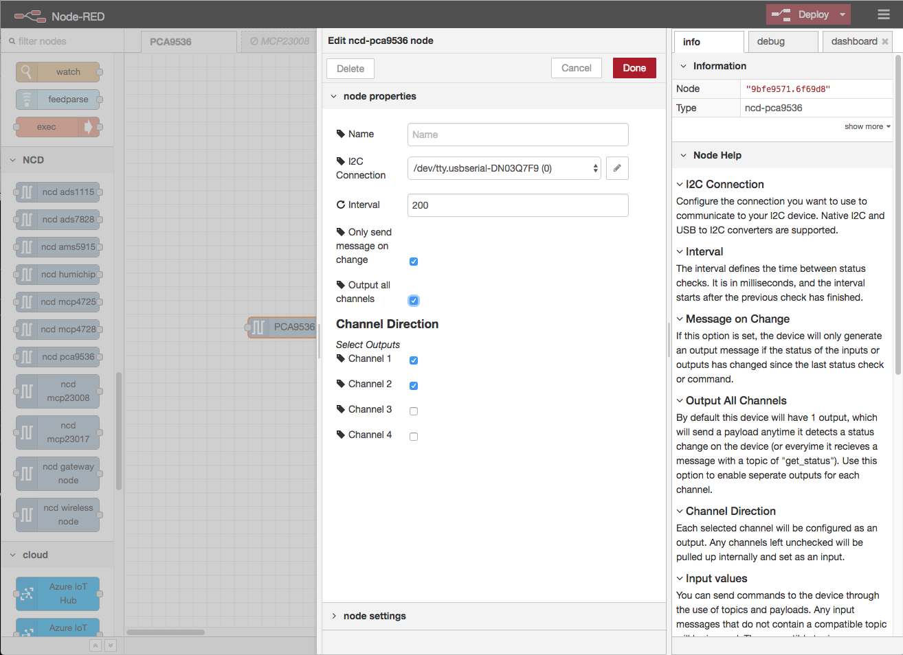
Now that you have an I2C Connection configured, go ahead and set up the rest of the device. There are instructions in the info pane that explain what each field is for, so we’ll just go through a basic configuration here.
If you are using inputs on the board, you probably want to be able to catch button presses and such, I generally set the interval pretty low for this, I’ve put it at 200 (ms) in this setup.
Since I’m using an interval, and don’t need to know when the status DOESN’T change, I’ve checked the “Only send message on change” checkbox.
To make reacting to events on specific channels easier, you can select “Output all channels” which will give you 5 total outputs, the first 4 of which are channels 1-4, the last output sends a payload that contains a JSON object with the state of all channels.
Lastly, I’m using a 2 channel relay board, so I uncheck channels 3 and 4 on the Channel Direction list, so the board knowns those are going to be used as inputs.
Once you’ve got this setup, click “Done” up top.
The node-red-dashboard package is a great way to quickly add a UI component to your project, we even use it during development of these libraries!

Control and Monitor
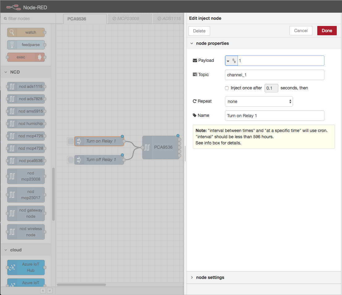
Now that we have our PCA9536 configured, we need to be able to use it. Node-red comes with a really handy node for testing things just like this, it’s called “Inject”. Let’s drag it over and set it up to control a relay.
There is a dropdown on the payload field you should use to select “09 Number” to define it’s a numeric payload, set the payload to 1. To control an individual channel, the topic of the message should be channel_{n}, in this case we’re just going to control channel 1, so we’re going to set the topic to “channel_1”.
I’ve given it a name of “Turn on Relay 1” and click Done. Since we may, at some point, need to turn this relay off, I’ve made a copy of the node (select the node and click cmd+c on mac, or cntl+c on windows, then cmd+v or cntl+v) and changed the payload of the copy to 0, and the name to “Turn off Relay 1”.
Once you’ve done that, drag the outputs of those Inject nodes over to the input of the PCA9536 node.
Now we can control the relay, but what if we need to act on a status change? Another node that gives us an easy way to see messages moving through the flow, is the “Debug” node. Grab one and move it to the right side of the PCA9536 node. By default, this node will print the payload of any message it receives to the Debug pane, since this is exactly what we want, all we need to do is drag the first output of the PCA9536 node over to the input of the debug node.
Your flow should now look something like the screenshot on the left. If it does, click on the “Deploy” button on the top right of the window.
All of those little blue dots will go away, indicating that your flow is up and running, and you can start testing! Click on the buttons next to your Inject nodes to turn your relay on and off, the debug window should show you a 1 or 0, respectively, whenever the relay status changes.
You can use the logic nodes, along with the input/output nodes that are a part of node-red to do some really cool stuff with your relay controller, more information about expected payloads and topics that the PCA9536 can utilize are available in the Info tab on the node itself, just double click on it any time to read up on how it works.
We hope you have as much fun playing with this as we did building it! If you find any issues, or would like to participate in the development, check out the GitHub repo. Check out the videos below for some ideas on the next steps to take.
TLDR; Import this flow
[{"id":"9bfe9571.6f69d8","type":"ncd-pca9536","z":"361b983.623d768","name":"","connection":"","interval":"200","onchange":true,"outputs":5,"output_all":true,"io_1":1,"io_2":1,"io_3":false,"io_4":false,"x":340,"y":400,"wires":[["afcea52e.bc87a8"],[],[],[],[]]},{"id":"d3577181.67446","type":"inject","z":"361b983.623d768","name":"Turn on Relay 1","topic":"channel_1","payload":"1","payloadType":"num","repeat":"","crontab":"","once":false,"onceDelay":0.1,"x":140,"y":380,"wires":[["9bfe9571.6f69d8"]]},{"id":"1421d918.16c8a7","type":"inject","z":"361b983.623d768","name":"Turn off Relay 1","topic":"channel_1","payload":"0","payloadType":"num","repeat":"","crontab":"","once":false,"onceDelay":0.1,"x":140,"y":440,"wires":[["9bfe9571.6f69d8"]]},{"id":"afcea52e.bc87a8","type":"debug","z":"361b983.623d768","name":"","active":true,"tosidebar":true,"console":false,"tostatus":false,"complete":"false","x":550,"y":380,"wires":[]}]