Input With Ease
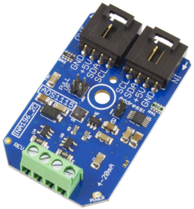
If you haven’t already, make sure to go through the setup tutorial. Once you’ve finished that we’re ready to go! The ADS1115 is a 4-channel, precision, low-power, 16-bit, I2C compatible, analog-to-digital converter. This chip is used in several of our ADC mini-modules, and also in our popular line of 4-20 mA current loop receivers.
If you haven’t already, get your devices plugged in, on a Raspberry Pi, that means installing the adapter, hooking up the I2C cable to the In port on the board. On any platform without native I2C, we’re going to assume you have a USB to I2C Adapter, which should also be connected to the board.
Now that you’re plugged in, let’s get this party started!
We are constantly working to improve our software libraries, as such, some of the screen shots in these articles may not reflect the latest functionality of the node. Please make sure to check out the "Info" tab on the node for the most up to date information.

Install the library
To make your life easier, we’ve build a library for the ADS1115 that provides a node-red node. This should prevent you from needing to muck about in the data sheet to find the appropriate I2C commands. You can use NPM to install this library from within your node-red directory (usually ~/.node-red):
npm install --unsafe-perm ncd-red-ads1115
You can try this command without the --unsafe-perm flag, it is there to allow nodeJS to access your hardware devices, it may not be necessary on all setups, but won’t hurt anything in any case.
Once this is done, spin up your node-red instance and you should see a node in the palette called ncd ads1115. Drag this on over to the dashboard, and double click to open the configuration form.
ALL of our ncd-red-* libraries are functional without node-red as well. Check out the 'test.js' file to see example usage for vanilla NodeJS development.
Configure the Node
I2C Connection
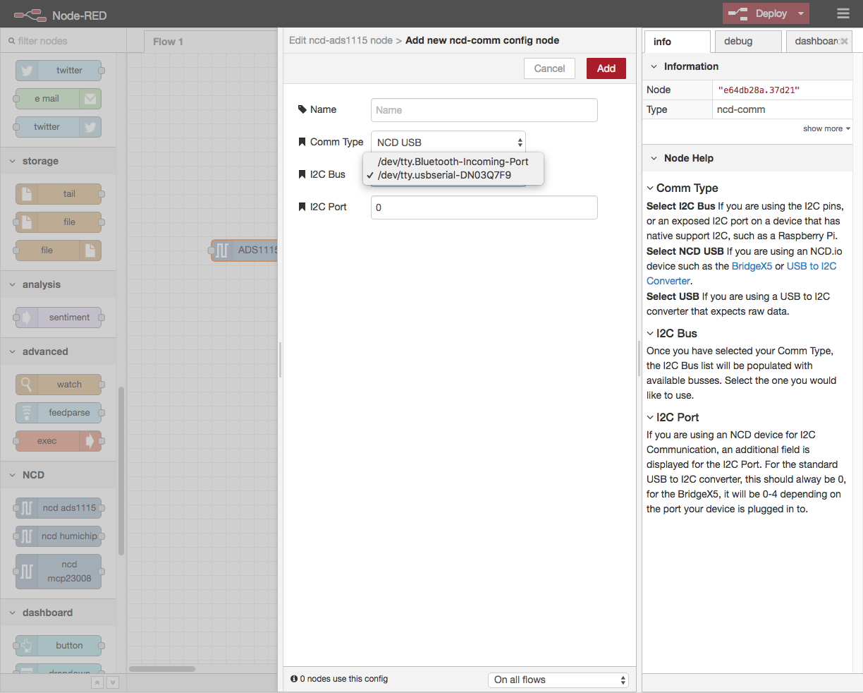
Once you’ve opened the configuration panel, you’ll need to set up the I2C connection, click on the pencil icon next to that field, and you’ll be presented with some simple options.
If you are using a native I2C port, select I2C Bus from the Comm Type drop down, this will pull in a list of active I2C Busses available on your device.
If you are using the USB to I2C adapter, select NCD USB, and select your USB device from the I2C Bus list. The I2C Port field should stay at 0, unless you are using a BridgeX5, in which case it should reflect the I2C Port you are using on that device.
Once that’s done, click Add at the top of the form to save your connection configuration, this will automatically attach it to your new ADS1115 node.
ADS1115 Setup
Now that you have an I2C Connection configured, go ahead and set up the rest of the device. There are instructions in the info pane that explain what each field is for, so we’ll just go through a basic configuration here.
The default I2C Address for this board is 72 (0x48), so if you don’t have a jumper installed on the address pins, you can leave that value as is.
Because this is an input board, we want to set the interval high enough to catch data changes to we can use them, if you are using this to read something like a temperature sensor, this value could be significantly lower, I’m going to set it to 1000 (ms) so we’ll check the reading once a second.
To make reacting to events on specific channels easier, you can select “Output all channels” which will give you n+1 total outputs, the first n correspond to channels that are not set to disabled, the last output sends a payload that contains a JSON object with the state of all channels.
I’m using a 4-20 mA converter for this application, so I’m going to set the multiplier to the value in the label text, 0.000628, which should give me approximately the correct value. I say approximately because there are minor variations from board to board, so you should calibrate this value to find the correct multiplier.
There are a lot of possible applications for this board, so I’m going to leave the Chip Configuration fields at their default values, which work perfectly for the 4-20 mA mini modules. I’m also going to make sure channel 1 is set to “Single Ended”, since I’m using the first channel of a 2 current loop receiver.

The node-red-dashboard package is a great way to quickly add a UI component to your project, we even use it during development of these libraries!
Monitor
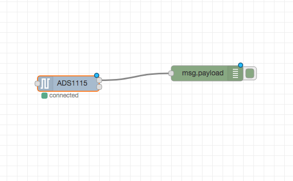
Now that we have our ADS1115 configured, we need to be able to use it. Node-red comes with a really handy node that gives us an easy way to see messages moving through the flow, the “Debug” node. Grab one and move it to the right side of the ADS1115 node. By default, this node will print the payload of any message it receives to the Debug pane, since this is exactly what we want, all we need to do is drag the first output of the ADS1115 node over to the input of the debug node.
Your flow should now look something like the screenshot on the left. If it does, click on the “Deploy” button on the top right of the window.
All of those little blue dots will go away, indicating that your flow is up and running, and you should now see data flowing into the debug pane!
You can use the logic nodes, along with the input/output nodes that are a part of node-red to do some really cool stuff with your mini module, more information about configuration and options for the ADS1115 are available in the Info tab on the node itself, just double click on it any time to read up on how it works.
We hope you have as much fun playing with this as we did building it! If you find any issues, or would like to participate in the development, check out the GitHub repo. Check back for next step videos we will be adding soon!
TLDR; Import this flow
[{"id":"49af52c3.60b31c","type":"ncd-ads1115","z":"981b34e4.f7a0f8","name":"","connection":"","addr":"72","interval":"1000","outputs":2,"output_all":true,"output_mult":"0.0003442","channel_1":"4","channel_2":"_none","channel_3":"_none","channel_4":"_none","gain":2,"mode":1,"rate":4,"compMode":0,"compPol":0,"compLat":0,"compQueue":3,"delay":"100","x":180,"y":260,"wires":[["1179117c.35b05f"],[]]},{"id":"1179117c.35b05f","type":"debug","z":"981b34e4.f7a0f8","name":"","active":true,"tosidebar":true,"console":false,"tostatus":false,"complete":"false","x":490,"y":240,"wires":[]}] Don’t forget to add your I2C Connection after you import this!