Introduction
By understanding and carefully configuring the Smart Mode parameters, you can optimize the Vibration Sensor v4 for a wide range of asset monitoring applications. This flexibility enables you to balance the need for detailed vibration data with efficient power usage and targeted event detection. Be sure to consider your specific application requirements and environment when configuring these parameters.
Industrial IoT Wireless Smart Vibration Sensor Gen4

Industrial IoT Wireless Vibration Temperature Sensor Gen4

Industrial IoT Wireless 2 Channel Vibration Temperature Sensor Gen4

Industrial IoT Wireless Ultrasound Vibration Temperature Sensor Gen4
msg types
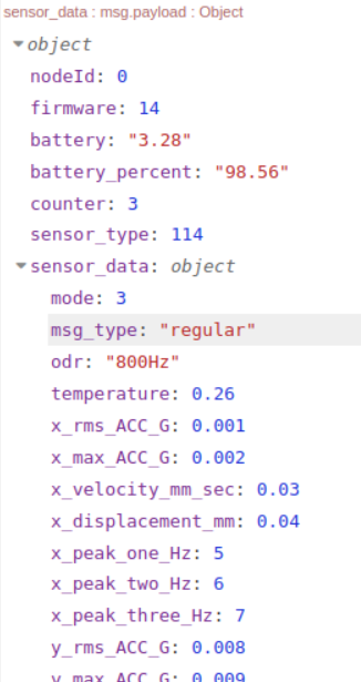
In Smart mode, the sensor can transmit two primary types of data, indicated by the msg_type field in the data payload:
Regular
This indicates data transmitted at the configured Sampling Interval. The transmission of this data (both processed and Time Domain (Raw) Data) is subject to the Smart Mode Threshold and Smart Skip Interval parameters.
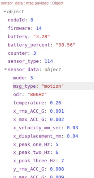
Motion
This indicates data triggered by the RMS acceleration exceeding the Acceleration Wake/Interrupt Threshold. The transmission of this data (both processed and Time Domain (Raw) data is also subject to the Smart Mode Threshold and Smart Skip Interval parameters.
Key Parameters
This section details the functionality and impact of the parameters that govern the sensor’s behavior in Smart mode.
Dead Band (mg)
- Description: This parameter defines a minimum acceleration value. Any acceleration reading below this value will be treated as zero.
- Impact: This helps to filter out very low-level vibrations that might be considered noise, leading to cleaner and more relevant data.
- Example: A dead band of 10 mg means that any measured acceleration below 10 mg on any axis will be reported as 0. If you put the sensor in a machine with a very low vibration, it is very possible you will get zero values on sensor data, in that case you should reduce this parameter.
Let’s say you install a sensor on a quiet pump motor in a noisy factory. Nearby machines, like a large air compressor or a CNC machine, are constantly vibrating. This external vibration travels through the floor and mounts, creating a low-level “noise” on your pump motor sensor, perhaps with a consistent reading of 5 mg.
You know that the pump is healthy, and a potential fault (like a failing bearing) would cause a vibration spike to 50 mg or more. To filter out the constant background noise, you set the dead band to 10 mg (for example). Now, the sensor will ignore the constant 5 mg of noise and only analyzes data when the vibration exceeds that dead band value. This gives you cleaner and more relevant data, preventing false alarms and ensuring that you are only alerted when a significant event occurs.
Sampling Interval
- Description: This parameter defines how frequently the sensor takes a vibration sample and checks against the Smart Mode Threshold and Smart Skip Interval for potential regular transmission.
- Impact: This interval controls the regularity of processed data transmissions when the vibration is above the Smart Mode Threshold and the Smart Skip Interval is met.
Acceleration Wake/Interrupt Threshold (Motion)
- Description: This parameter specifies the vibration level that triggers the sensor to evaluate potential ‘motion’ data transmission (including Processed Data and Time Domain (Raw) Data, if configured).
It allows the user to specify a vibration threshold indicating that the machine is ON, for example. When the vibration exceeds this level, the sensor’s internal uptime counter increases. This uptime value is included in the FLY message.
- Impact: This feature is essential for detecting sudden or intermittent high-vibration events, even between regular sampling intervals. Data transmitted due to this trigger will have the msg_type set to “motion.” However, transmission is conditional on checks against the Smart Mode Threshold and Smart Skip Interval. If these conditions are not met, no ‘motion’ data transmission will occur.
- Example: Setting the threshold to 3 (150 mg) will cause the sensor to evaluate data transmission if the RMS acceleration on any axis exceeds 150 mg. The sensor will only transmit data after confirming that the Smart Mode Threshold and Smart Skip Interval conditions are satisfied. If either condition is not met, no ‘motion’ transmission will occur. (Check Flowchart).
Auto Raw Interval
- Description: This parameter determines how often the sensor evaluates and potentially transmits Time Domain (Raw) data after a Processed data transmission automatically. The value set here is a multiplier of the Sampling Interval.
- Impact: This setting enables periodic ‘regular’ or ‘motion’ transmission of Time Domain data vibration data without requiring manual, custom or smart requests. The Auto Raw Interval controls the frequency of potential Time Domain (Raw) data transmissions, provided the vibration exceeds the Acceleration Wake/Interrupt Threshold-Motion (if enabled), Smart Mode Threshold and the Smart Skip Interval conditions are met. (Check Flowchart)
Auto Raw Destination Address
- Description: This parameter specifies the network address (the MAC address of your gateway) where the automatically transmitted Time Domain (Raw) data packets will be sent.
- Impact: Setting a specific destination address (unicast) improves the reliability of Time Domain (Raw) Data transmission, especially given the large size of raw data packets, as it often involves a check mechanism to ensure data delivery. Broadcasting raw data is generally not recommended.
Examples:
1. With Sampling Interval is 5 minutes, Auto Raw Interval as 1 (5 minutes), Dead band is set to 10 mg, Smart Mode Threshold is set to 100mg and Smart Mode Skip is 1, then if the sampling interval meets (5 minutes) and vibration data on any axis exceed 100mg (120mg for example), Auto Raw Interval meets (5 minutes), then the sensor will transmit ‘regular’ processed data and then a few seconds after sensor will transmit a ‘regular’ Time Domain data.
2. With Auto Raw Transmission is enabled, Sampling Interval is 5 minutes, Dead band is set to 10 mg, Smart Mode Threshold is set to 100mg and Smart Mode Skip is 1, then if the sampling interval meets and vibration data on any axis does not exceed 100mg (95mg for example), then the sensor will skip a first transmission (due to Smart mode skip interval 1), sensor does not transmit data, then after 5 minutes, if vibration data on any axis does not exceeds 100mg, (now smart mode skip interval meets), the sensor will transmit only a ‘regular’ processed data and does not transmit a ‘regular’ time domain data due to vibration data on any axis does not exceed the smart mode threshold in any of the two intervals.
Smart Mode Threshold
- Description: This parameter specifies the minimum RMS acceleration level (on any X, Y, or Z axis) required for the sensor to allow data transmission (including Processed Data and Time Domain (Raw) data transmission, if configured). Transmission occurs at the configured Sampling Interval or when triggered by ‘the Acceleration Wake/Interrupt Threshold ‘(if enabled) and if the RMS acceleration level in any axis is above the Smart Mode Threshold value. All regular or motion transmissions are evaluated against the Smart Mode Threshold and Smart Mode Skip Interval before being sent.
All RMS vibration values that are lower than Smart Mode Threshold, a potential sensor data transmission is conditioned by Smart Skip Interval Value.
- Impact: This threshold filters out transmissions during periods of normal or low vibration, conserving power and prioritizing significant vibration events.
- Example: Setting the Smart Mode Threshold to 5 (250mg) means that a transmission will only potentially occur if the RMS acceleration on any axis exceeds 250 mg (5 × 50 mg).
Smart Mode Skip Interval
- Description: This parameter dictates how many consecutive sampling intervals the sensor will skip transmitting data if the RMS acceleration remains below the Smart Mode Threshold. All regular or motion transmission that RMS acceleration is below to Smart Mode Threshold will be evaluated by Smart Mode Skip Interval before being transmitted.
- Impact: This further optimizes power consumption by preventing redundant transmissions during sustained periods of low activity. After the skip interval is complete, a processed data packet will be transmitted once, even if the vibration is still below the threshold.
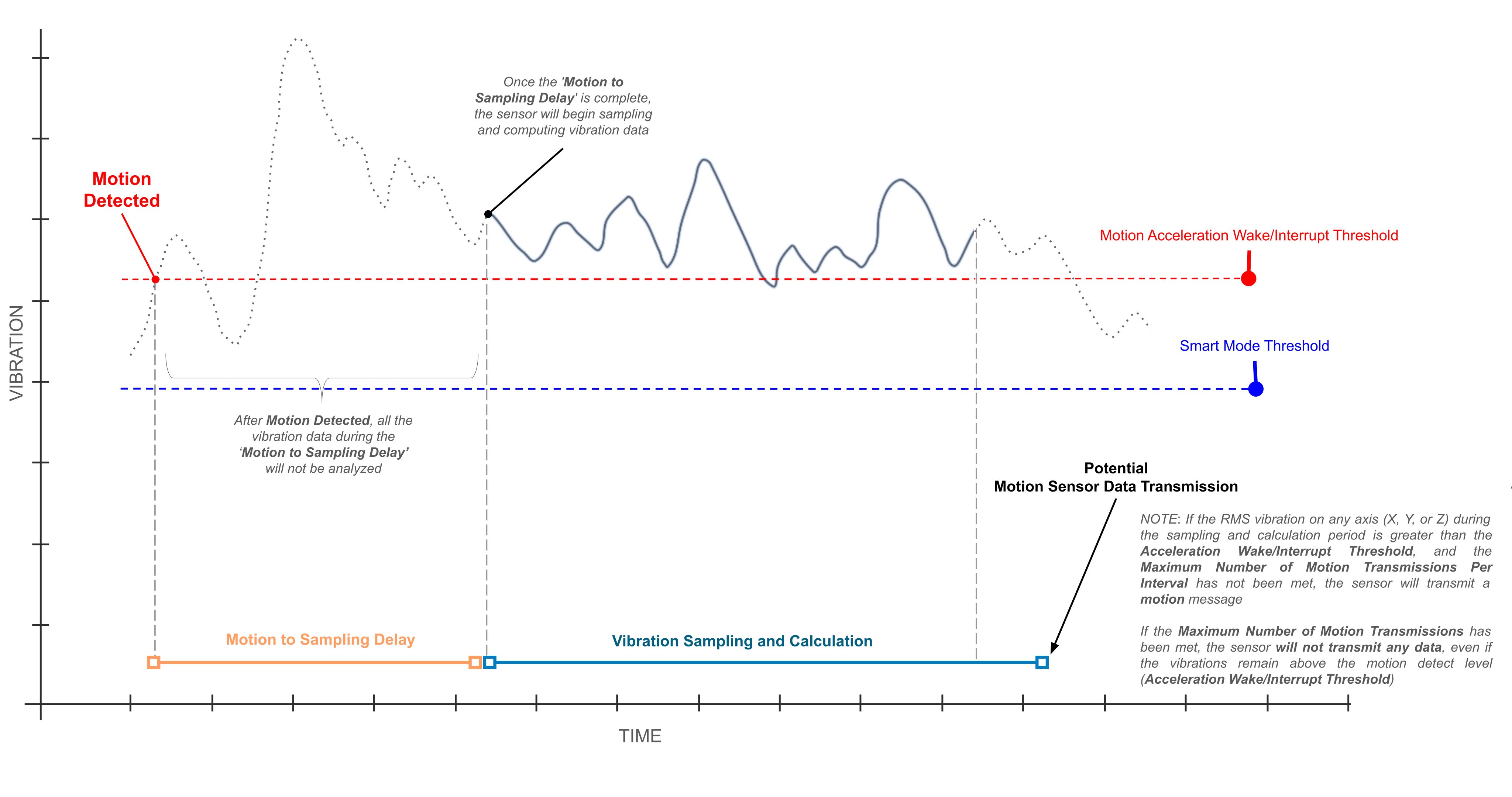
Motion to Sampling Delay
- Description: This parameter specifies the time, in milliseconds, that the sensor will wait after detecting a Motion (vibration that is above the Acceleration Wake/Interrupt Threshold). After this delay, the sensor begins sampling and computing the vibration data for a potential transmission. The sensor will ignore any vibrations during this period.
Impact: Any vibration data that occurs during this delay period will not be analyzed by the sensor. This is a crucial setting for filtering out short-lived, insignificant events. This command only applies to sensors with firmware version 6 and above.
Example: See the visual example in the chart below.
Max Number Motion Transmission Per Interval
- Description: This parameter defines the maximum number of “Motion” data transmissions the sensor can send within a single Sampling Interval. Once this limit is reached, the sensor will not send any more motion messages, regardless of vibration levels, until the next Sampling Interval begins.
- Impact: This mechanism helps to significantly conserve battery power by preventing the sensor from transmitting a continuous stream of data during prolonged periods of high vibration. Setting this to a higher value will reduce battery life. This setting only applies to sensors with firmware version 6 and above.
- Example: Let’s say your Sampling Interval is 5 minutes and you set the Max Number of Motion Transmissions per Interval to 2. If the vibration exceeds the motion threshold at minute 1, the sensor will transmit a motion message. If the vibration is still high at minute 2, it will transmit a second message. However, if the vibration remains high at minute 3, the sensor will not transmit another motion message because it has already reached the maximum of two transmissions for that interval. The sensor can only send a new motion transmission at the start of the next 5-minute interval, provided the vibration is still above the threshold.
For all sensor configuration descriptions, we recommend to take a look at User Manual:
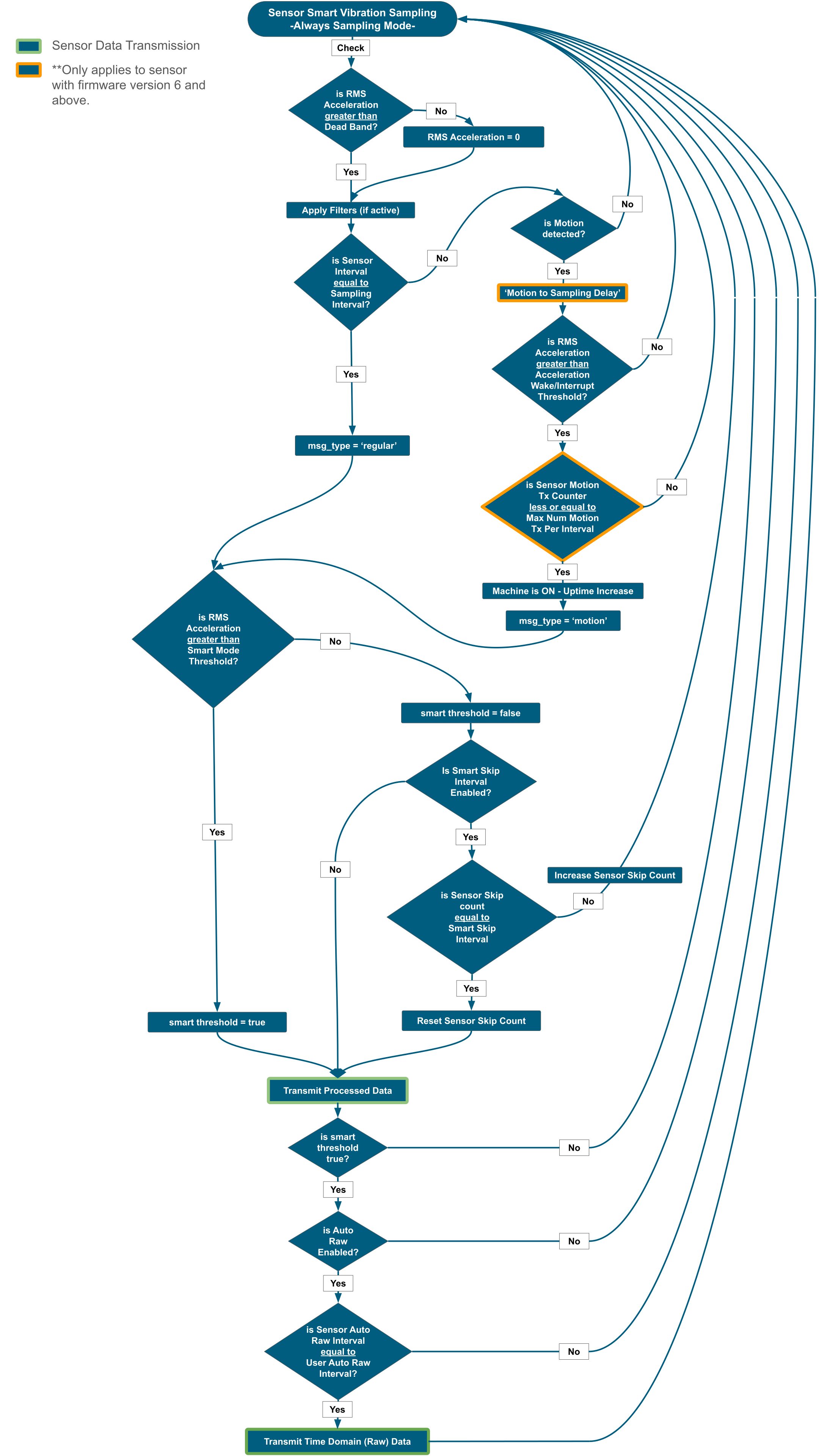
Flowchart
Practical Configuration Examples
This section provides practical use cases with example configurations to illustrate how the Smart mode parameters influence the sensor’s behavior.
Use Case 1: Basic Monitoring at Defined Intervals
Goal: Monitor a continuously running machine and receive ‘regular’ processed data every 10-30 minutes.
Configuration:
- Mode: Smart
- Sampling Interval: 10 minutes
- Auto Raw Interval: 0 (Disabled)
- Auto Raw Destination Address: (Disabled)
- Smart Mode Threshold: 1 (50 mg) – Assuming minimal baseline vibration. Adjust as needed based on your environment.
- Smart Mode Skip Interval: 3 (default) or 0 (Disabled)
- Acceleration Wake/Interrupt Threshold: 0 (disabled for this use case)
- Dead Band in mg: (Set as appropriate for your environment)
Expected Sensor Behavior:
Upon initial power-up and baseline learning, the sensor will start sampling and computing every 10 minutes, If the RMS acceleration exceeds 50 mg on any axis (Smart Mode Threshold value), the sensor will transmit processed data (msg_type: ‘regular’), when RMS Acceleration exceeds Smart Mode Threshold, then Smart Mode Skip Interval is not evaluated.
If RMS acceleration remains below 50 mg for three consecutive 10-minute intervals, it will skip transmission (Smart Mode Skip Interval value). On the fourth interval, it will transmit processed data once, even if still below the smart threshold.
Use Case 2: Basic Monitoring with Automatic Raw Data for Periodic Detailed Analysis
Goal: Monitor a continuously running machine and receive ‘regular’ processed data every 5 minutes. Additionally, receive a detailed Time Domain (Raw) data sample every hour for in-depth analysis if RMS acceleration exceeds Smart Mode Threshold value.
Configuration:
- Mode: Smart
- Sampling Interval: 5 minutes
- Auto Raw Interval: 12 (12 × 5 minutes = 60 minutes)
- Auto Raw Destination Address: (Set to your gateway’s MAC address)
- Smart Mode Threshold: 1 (50 mg) – Assuming minimal baseline vibration. Adjust as needed based on your environment.
- Smart Mode Skip Interval: 3 (default)
- Acceleration Wake/Interrupt Threshold: 0 (disabled for this use case)
- Dead Band in mg: (Set as appropriate for your environment)
Expected Sensor Behavior:
Upon initial power-up and baseline learning, the sensor will start sampling every 5 minutes.
If the RMS acceleration exceeds 50 mg on any axis (Smart Mode Threshold value), the sensor will transmit processed data (msg_type: ‘regular’). If it remains below 50 mg for three consecutive 5-minute intervals, it will skip transmission (Smart Mode Skip Interval value). On the fourth interval, it will transmit processed data once, even if still below the threshold.
Every 60 minutes, the sensor will automatically transmit Time Domain (Raw) data to the configured Auto Raw Destination Address only if the Acceleration value is above the Smart Mode Threshold value.
Use Case 3: Event-Driven Monitoring with Motion Detection
Goal: Primarily monitor a machine that operates intermittently. Only transmit data when significant vibration occurs, and receive regular processed data every 60 minutes as a heartbeat.
Configuration:
- Mode: Smart
- Sampling Interval: 60 minutes
- Auto Raw Interval: (0 – Disabled)
- Auto Raw Destination Address: (Disabled)
- Smart Mode Threshold: 2 (100 mg) – To allow regular transmissions during operation.
- Smart Mode Skip Interval: 3 (default)
- Acceleration Wake/Interrupt Threshold: 4 (200 mg) – To immediately capture significant vibration events.
- Dead Band in mg: (Set as appropriate)
Expected Sensor Behavior:
The sensor continuously samples vibration. If the RMS acceleration exceeds 200 mg on any axis, uptime will increase and the sensor will immediately transmit processed data with msg_type: ‘motion’.
If the RMS acceleration exceeds 100 mg at regular 60-minute sampling interval, the sensor will transmit processed data (msg_type: ‘regular’). If it stays below 100 mg for next three intervals, it will skip, and transmit once on the fourth.
Use Case 4: Testing Auto Raw Data Transmission on a Stationary Device
Goal: Verify the functionality of the Auto Time Domain (Raw) data transmission on a sensor placed on a stationary desktop.
Configuration:
- Mode: Smart
- Sampling Interval: 1 minute
- Auto Raw Interval: 1 (1 × 1 minute = 1 minute)
- Auto Raw Destination Address: (Set to your gateway’s MAC address)
- Smart Mode Threshold: 1 (50 mg)
- Smart Mode Skip Interval: 0 (Disabled)
- Acceleration Wake/Interrupt Threshold: (Disabled)
- Dead Band in mg: (Set as appropriate, e.g., 0 to account for minimal ambient vibrations)
Expected Sensor Behavior:
Since the Smart Mode Threshold is set to 50 mg, and assuming the ambient vibration on the desktop is below this, the transmissions will be processed data only (msg_type: ‘regular’), occurring every minute.
Because the Auto Raw Interval is set to 1, the sensor will attempt to transmit Time Domain (Raw) data every minute following the processed data transmission. However, the sensor will only transmit Auto Time Domain (Raw) data if the vibration exceeds 50 mg (Smart Mode Threshold).
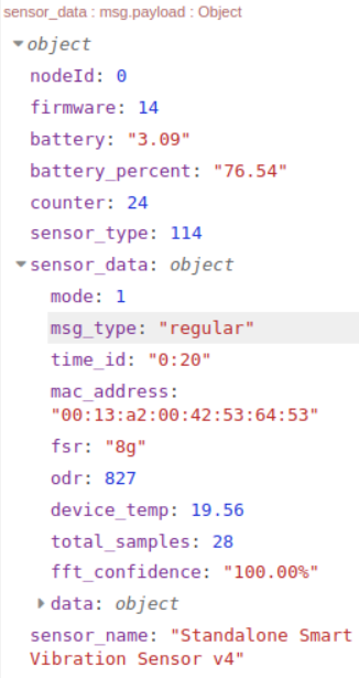
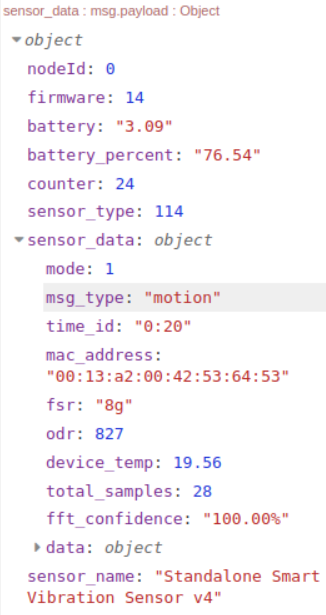
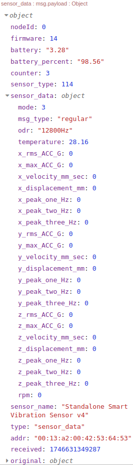
Why Zero Values in Processed Data?
If your sensor is in Smart Mode (the default setting) and you are receiving zero values in the processed vibration data payload, (Or, you may be receiving zero values at time intervals longer than what you have defined) as the right image, this could be due to several reasons, which we will explain below:
Scenario 1: The sensor is situated on a powered-off or stand-by machine, a desktop, or in a location experiencing no movement during the Sampling Interval.
Scenario 2: Sensor on a Machine Exhibiting Very Low Vibration Levels
Behavior: The sensor initiates Smart vibration sampling based on the configured Output Data Rate (ODR), Sampling Interval, Filters, and Full Scale Range (FSR). Given the low vibration or absence of movement in these scenarios, the sampled vibration values will be close to zero. The sensor applies the Dead Band filter (set to 20mg by default). As none of the vibration values exceed this Dead Band, they are treated as zero. The sensor then proceeds to evaluate if the Sampling Interval has elapsed. If so, the msg_type property in the data payload will be set to ‘regular‘. Next, the sensor checks the Smart Threshold (500mg by default). Since the vibration values are zero, this threshold is not met, which will prevent the transmission of Processed data (or Auto Time Domain (Raw) data – even if enabled). This entire process of smart sampling, checking the Dead Band and Smart Threshold, and skipping transmission repeats for the duration of the Smart Skip Interval (default is 3). On the fourth sampling interval after the last successful transmission (or sensor reset), the Smart Skip counter will be met, and the sensor will transmit a regular processed data payload containing all zero values, without the option for Auto Raw Transmission. Consequently, under these conditions and with a 1-minute Sampling Interval, you will receive regular processed data with zero values every 4 minutes.
Recomendations.
If your intention is to test the sensor on your desktop before installing it on your machine, or if the sensor is already mounted but the machine’s vibrations are very low, we recommend adjusting the Dead Band value. For example, setting the Dead Band to 0 will ensure that even very low vibration values are not treated as zero (noise).
We also recommend setting the Output Data Rate to a lower value (depending on your specific target machine) and configuring the Smart Threshold to 1. This will set the threshold to 50 mg, a very low vibration level. Additionally, you can set the Smart Skip Interval to 0 to prevent the sensor from skipping transmissions when vibration values are below the Smart Threshold parameter.
With these adjustments, the sensor’s behavior will change, and you should observe non-zero vibration data in the sensor transmissions. In the case of desktop testing, we recommend applying slight movement to the sensor to generate low vibrations. Even with these settings, if the sensor consistently samples zero vibration values, the behavior described previously will still apply.
For available and default Vibration Version 4 parameters, please refer to the User Manual and Datasheet.