Overview
This document offers clear, step‑by‑step instructions for positioning, mounting, powering, and commissioning the NCD PR52‑33T long‑range wireless ultrasonic tank‑level sensor. Follow these guidelines to obtain reliable level readings and maintain a robust RF link.
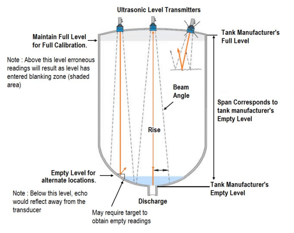
How Ultrasonic Tank‑Level Sensing Works
The probe emits a short 42 kHz acoustic pulse, then measures the round‑trip echo time to the liquid surface. The sensor converts this time to distance (millimetres), applies temperature compensation, and transmits the value over DigiMesh® at user‑defined intervals.
Feature
- Reading-to-Reading stability of 1mm at 1 Meter (typical)
- 500 to 9999mm Measurement Range with 1mm Resolution
- 40 to 499mm Measurement Range with Reduced Reliability
- Target Size Compensation for Greater Consistency and Accuracy
- Fully Calibrated and Linearized with Temperature Compensation
- Long Range Wireless Range of Up to 2 Miles Line of Sight
- 128-Bit AES Encrypted Wireless Communications
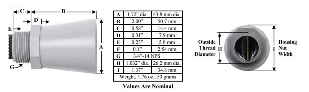
- Standard Electrical 3/4″ PVC Pipe Fitting
- Supports Smart Percentage Detection Change Mode
- Validates and Retries on Lost Communication Packets
Pre‑installation Checklist
| Task | Why it matters | Quick Check |
|---|---|---|
| Verify tank depth ≥ 0.6 m | Leaves the 500 mm blanking zone free | Measure interior height |
| Confirm rigid ¾" port on tank roof | Matches probe threads | Inspect hatch |
| Plan antenna path to gateway | Metal attenuates 900 / 868 MHz signals | Perform RSSI test |
| Note presence of foam or turbulence | May require still‑well | Observe filling |
| Ensure 1.9 m probe lead reaches mount | Avoid cable extensions | Measure distance |
Mechanical Mounting
Choosing a Location
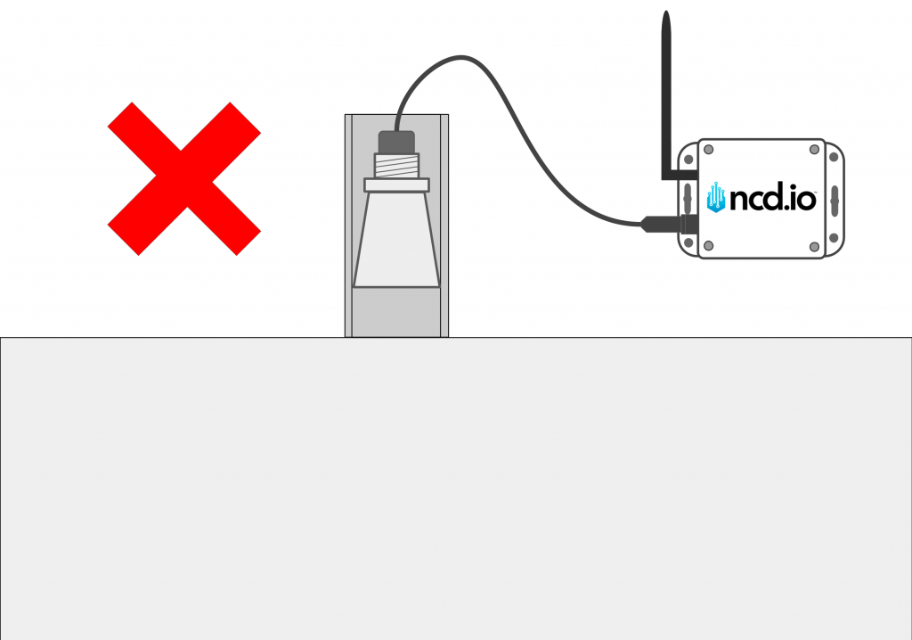
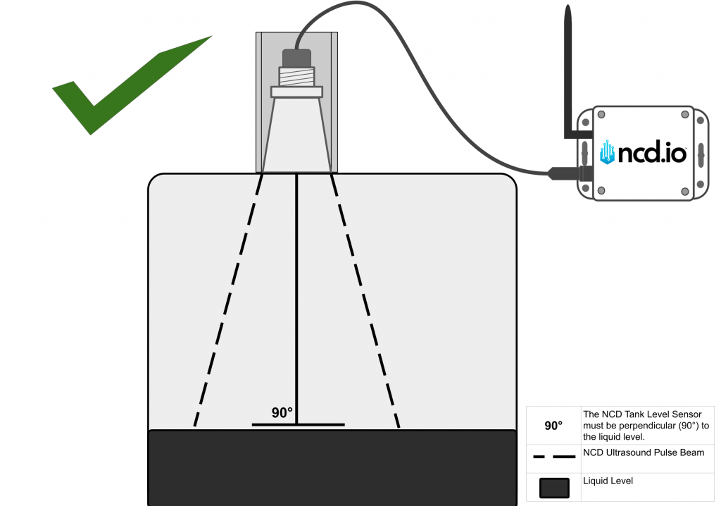
Never recess the probe into a nozzle—the lip produces false echoes.
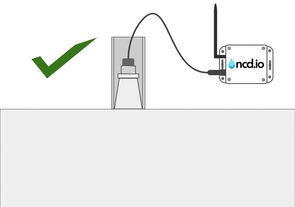
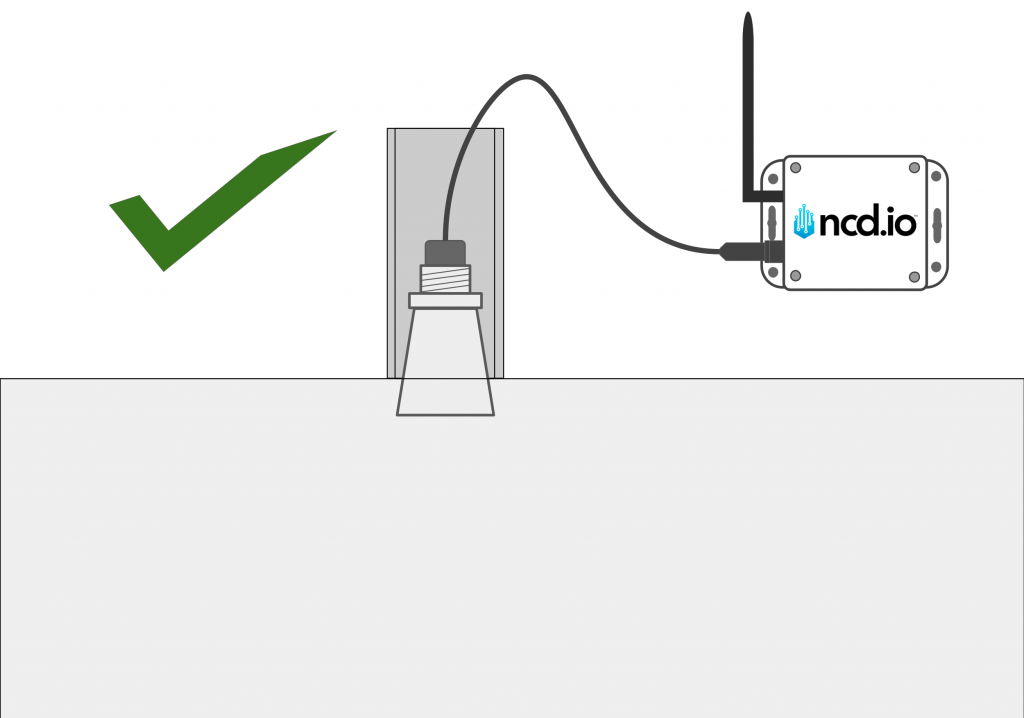
Flush or slightly proud of the tank roof.
Offset 25 – 75 mm from the centreline to avoid agitators or fill pipes.
Maintain at least 600 mm clearance from the nearest wall to reduce reflections.
Keep the 8° conical beam path free of cables, ladders, and structural members.
Threads and Sealing
Thread the probe directly into a ¾” PVC female hub.
When using ¼ ”NPT or ¼”-28 UNF studs, fit the bracket plate and PTFE gasket to preserve IP67 integrity.
Apply thread‑seal tape and tighten only on the hex boss—never twist the cable.
Height and Distance Rules
| Spec | Value | Note |
|---|---|---|
| Blanking (dead‑band) | 500 mm | Mount ≥ 550 mm above “full” |
| Confirm rigid ¾" port on tank roof | Matches probe threads | Use an adapter if needed, proper mounting is essential for good sensor alignment |
| Maximum span | 9 999 mm | Minimises reflections |
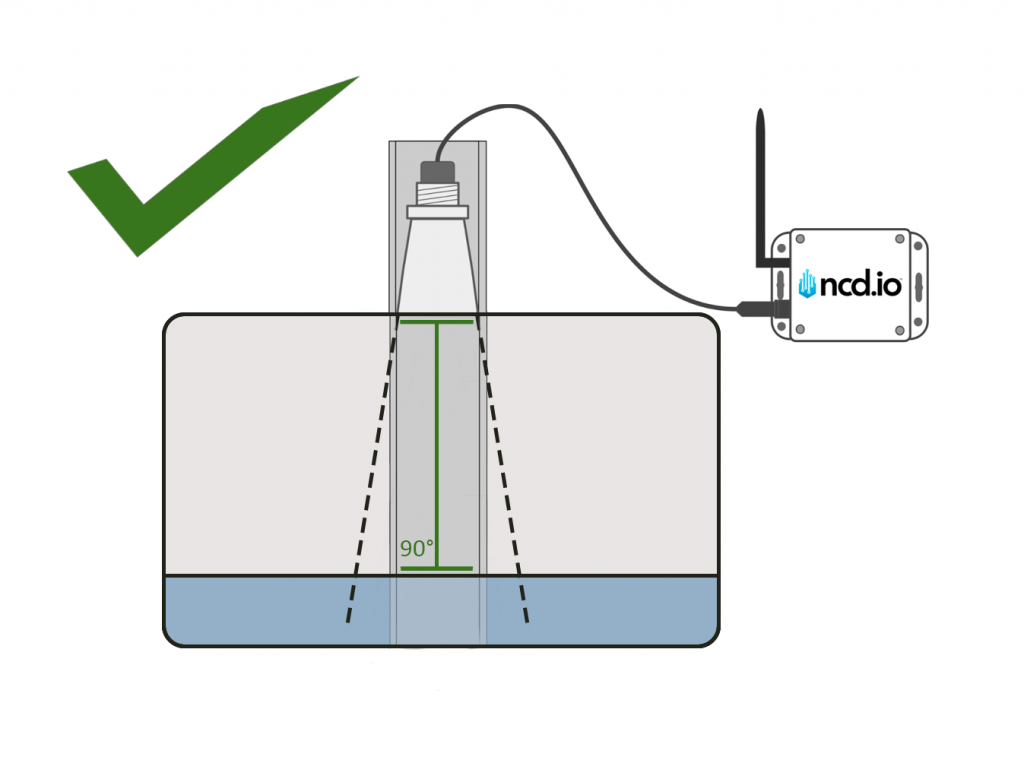
Pipe / Stilling‑Well (optional)
A stilling-well can deliver stable, repeatable readings in foamy or turbulent tanks, but only when the pipe is selected and prepared correctly. Use the following guidelines to minimize false echoes and drift.
When to use a stilling-well
Persistent foam, heavy agitation near inlets, floating debris, or narrow access hatches that expose the beam to obstructions.
Pipe selection
Use smooth, seamless PVC/HDPE pipe, Schedule 40 or thicker.
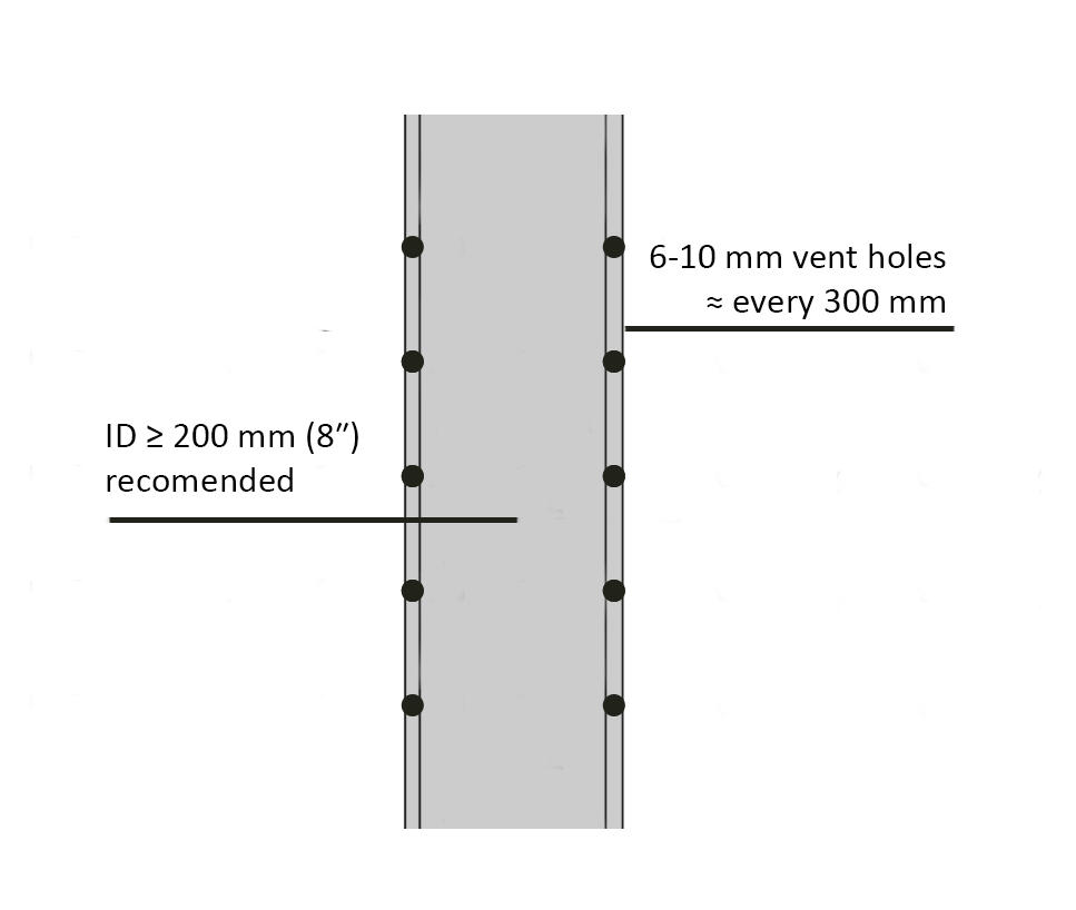
ID ≥ 200 mm (8″) recommended; smaller diameters (e.g., 150 mm / 6″) may work but increase the risk of wall reflections and drift.
Avoid couplings and internal lips. If sections must be joined, machine or sleeve the joint so the interior is perfectly smooth.
Do not use corrugated, ribbed, or fully slotted pipe. Narrow slots or perforations create strong internal reflections and limit ranging depth.
Geometry & installation
Mount the probe so the sensor face is flush with the inside bore of the pipe; do not recess it above the opening.
Cut the pipe top square and flush to the probe face; avoid any overhang that forms an acoustic lens.
Provide vent holes (6–10 mm) near the top and at intervals to equalise pressure and allow smooth liquid movement into/out of the well.
Keep the well vertical and the probe perpendicular (90°) to the liquid surface.
Moisture & fouling
Keep the inside surface free of droplets/condensation—droplets act as unintended reflectors and may be reported as targets.
Plan for periodic cleaning to remove sludge or scale at typical liquid levels; interior build‑up can appear as a false target.
Potential issues in pipes
Multipath reflections (bounces off the wall before hitting the surface) can make the reported level appear to “walk” by 1–2 cm (occasionally 5–10 cm) with temperature changes.
Phase cancellation at certain depths/temperatures can temporarily mask the true echo.
Pointing a pipe into open air forms an acoustic lens at the mouth; the sensor tends to range only to the pipe end, not beyond.
Commissioning tips
Bench‑test the sensor with the intended pipe before permanent install.
Log a full fill/empty cycle and check for step changes at joint heights; replace or re‑work the pipe if artefacts are present.
Wireless and Power Guidelines
Mount the transmitter enclosure and antenna outside the tank; keep the antenna vertical and ≥ 300 mm from metal surfaces.
Select 900 MHz (North America) or 868 / 2.4 GHz (EU / global) as required.
Battery‑only mode supports up to 10 years at one transmission per hour. Provide 5 – 12 V DC external power for faster logging.
Maintain ambient enclosure temperature within the range 0° C to +40 °C for optimal battery life (as tested by NCD).
Environmental Considerations
| Challenge | Mitigation |
|---|---|
| Heavy foam or agitation | Mount the probe in a still‑well (Pipe/Stilling=Well) |
| Condensing humidity | Tilt probe 2 – 3° to shed droplets |
| Corrosive vapours (H₂S, acids) | Order PF‑coded chemical‑resistant probe |
| Solar heating of enclosure | Shade the box or mount on the north side |
Start‑up and Configuration
Slide the power switch to Battery (or Ext if externally powered).
Press RESET; one LED blink confirms boot‑up.
Open Node‑RED and confirm the live distance reading.
Set the Transmission Interval as desired.
After readings stabilize, bolt down the transmitter enclosure and secure the hatch.
Maintenance
Perform an annual visual check for condensation, thread tightness, and antenna integrity.
Replace the battery when Battery % < 15 % (≈ 2.6 V).
Re‑zero after cleaning or replacing the probe.
Troubleshooting
| Symptom | Likely cause | Remedy |
|---|---|---|
| Constant 500 mm reading | Target < 300 mm or heavy foam | Add still‑well or raise probe |
| Constant 9 999 mm reading | No echo detected | Remove obstructions |
| RSSI < –90 dBm | Antenna blocked | Elevate or relocate antenna |
| LED blinks three times after transmit | Radio fault | Reseat Digi XBee module |
Appendix A. Ideal Mounting Diagram