- only applicable for gen 1 hardware
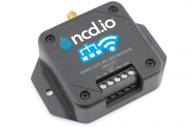
- Industrial Grade IoT Wireless RS485 Modem
- Receive Wireless Sensor Data from NCD Sensors
- Ideal For using ncd.io sensors with PC based RS485
- Converts Wireless Data to Serial RS485 Data As it Is
- Operating Temperature Range -40 to +85 °C
- 5V-32V DC Input Voltage Range
- Works With PC, MAC, Linux and Edge Gateway
- 2 Mile Range with On-Board Antenna
- Wireless Mesh Networking using DigiMesh®
- Available in 3 Versions for use with PLCs and PCs
Introduction RS485 to Wireless
The NCD RS-485 to Wireless Adapter converts data in both direction between Wireless and RS-485 communications. Inside the modem, you will see a small module, which actually handles the conversion process. This documentation will reference this module and all applicable jumper settings.
There are 3 versions of this modem, which will be covered in this guide. The communication protocols are slightly different for each version. We will start the guide by covering the hardware, and then move on to protocol for all 3 versions. Please note this guide will discuss commands in hex values ONLY.
Also, please note the default RS-485 Communications Baud rate is 9600. We suggest using the default settings for best results.
Getting to Know NCD RS-485 Node Modules
NCD RS-485 Node modules are a modular technology, allowing most NCD devices to be retrofitted with RS-485 communication capabilities. Node modules have a number of options and jumper settings available, allowing you to adapt the module in a number of ways. NCD Node modules are preconfigured for RS-485 communications at 9600 baud. Node modules communicate to the host device at 57.6k baud by default. Baud rate settings are programmable via RS-485. The C jumper must be installed for configuration. The node module must power-up with the C jumper installed. Similarly, once configuration is complete, the node module must be powered up with the C jumper removed for proper operation.

RS-485 Node Module Hardware Description
The NCD Node Module has a Atmel processor and one RS485 transceiver (SN65HVD12D). The On board processor has 2 USARTS. One USART is connected to the RS-485 trans receiver and the other USART communicates to the host device. NCD RS-485 node modules operate at 3.3V DC. This communications module includes bus pin short protection from -7V to 12V DC and 16kV ESD protection. Up to 256 nodes may be connected on the bus simultaneously. For longer communication distances, low baud rates (such as 9600 baud) are recommended.
NCD RS-485 node modules act as RS-485 to USART converter. Since USART communications is available on most computing platforms, it’s possible for most computing devices to communicate via RS-485 with the correct adapter.
- Raspberry Pi 2 and 3 to Modular Communications Adapter allows RS-485 communications with a Raspberry Pi 2 or 3
- Arduino to Modular Communications Adapter allows RS-485 communications with Arduino Uno
- Particle Photon to Modular Communications Adapter allows RS-485 communications with a Particle Photon
- Particle Electron to Modular Communications Adapter allows RS-485 communications with a Particle Electron
- BeagleBone Communications Adapter allows RS-485 communications with a BeagleBone White or Black
- Onion Omega to Modular Communications Adapter allows RS-485 communications with Onion Omega 1 or 2
RS-485 Node Jumpers
Be sure to install jumpers, then power-up the module. Module must be power-cycled anytime the jumpers are changed. Jumper settings only take effect on power-up.
1, 2, 3 Jumpers: RS-485 Bus Termination
- Set J3 Jumper when the node device is the first device on the bus.
- Remove all jumpers when the device is in between the first and last device on the bus.
- Set J1, J2, and J3 when the device is the last or only device on the bus.
BR Jumper
The BR jumper is not currently used in this design, but is reserved for future use.
C Jumper: Configuration Mode
This jumper is used to put the module in configuration mode. This jumper must be installed to change the baud rate. Be sure to power-cycle the module after any jumper change. Jumper settings are read during power-up only. Use the RS-485 port to write configuration data into the module. The RS-485 baud rate in configuration mode depends on the settings stored in the module. You may test the baud rate using the read commands below.
Changing Baud Rates
Change the USART Baud Rate
Send the Following Bytes via RS-485:
9600 Baud USART: F3, 00, 25, 80
19,200 Baud USART: F3, 00, 4B, 00
38,400 Baud USART: F3, 00, 96, 00
57,600 Baud USART: F3, 00, E1, 00
115,200 Baud USART: F3, 01, C2, 00 (Experimental, Not recommended as there may be communications problems)
Read USART Baud Rate: 245 (Three Bytes will be Returned Indicating the Baud Rate)
9,600: 00 25 80
19,200: 00 4B 00
38,400: 00 96 00
57,600: 00 E1 00
115,200: 01 C2 00
Change the RS-485 Baud Rate
Send the Following Bytes via RS-485
9600 Baud USART: F4, 00, 25, 80
19,200 Baud USART: F4, 00, 4B, 00
38,400 Baud USART: F4, 00, 96, 00
57,600 Baud USART: F4, 00, E1, 00
115,200 Baud USART: F4, 01, C2, 00 (Experimental, Not recommended as there may be communications problems)
Read USART Baud Rate: 246 (Three Bytes will be Returned Indicating the Baud Rate)
9,600: 00 25 80
19,200: 00 4B 00
38,400: 00 96 00
57,600: 00 E1 00
115,200: 01 C2 00
Note: New setting will apply only on power-up.
Factory Reset Procedure
This should be done only when absolutely necessary. To reset the module, follow these steps in order:
- Power-down the module.
- Install the C jumper.
- Power-up the module.
- Connect CLR to 3.3V for 1 Second using a Jumper Wire
- Module will Reset the USART to 57.6k Baud
- Module will Reset the RS485 Port to 9600 Baud
- Power-down the module.
- Remove the C Jumper
- Power-Up the module and use default settings.
Note: If the bus length exceeds more than 5,000 feet, users may experience data corruption.
Standard Version Communications Protocol
The Standard Version of this device communicates raw data between the Digi XBee module and the RS-485 link. This version is ideal for desktop computers that have the resources to properly generate and decode Digi API communication frames. If you are unfamiliar with Digi API communication frames, please reference the following document from the Digi Web Site:
Below, you will find a couple of examples, note the Standard Version of this device acts as a raw conduit for communications and conversion between wireless and RS485. Incoming data on the RS-485 port is directly communicated to the XBee wireless communications module. Likewise, incoming Wireless data is directly converted to RS485 data.
Incoming and Outgoing Data are Always the Same:
Example Incoming Wireless Data -- 7E 00 19 90 00 13 A2 00 41 91 1B 83 FF FE C2 7F 00 04 03 FF 80 00 01 00 0F A1 F7 40 9E
Example of Outgoing Data on the RS485 Port --  7E 00 19 90 00 13 A2 00 41 91 1B 83 FF FE C2 7F 00 04 03 FF 80 00 01 00 0F A1 F7 40 9E
AutoEncoder Version Communications Protocol
The AutoEncoder Version of this device handles data in a slightly different way when compared to the Standard Version of this device. The AutoEncoder version of this device automatically generates the API frame for wireless communications, making communications with Digi modules much easier to manage. Similarly, incoming wireless data is decoded and converted to a raw payload on the RS-485 port. All the user needs to worry about are a few commands, and raw payload data. The AutoEncoder version will wrap up and unwrap all wireless data and convert to RS-485 data. There is a speed penalty for this conversion, so it is slower than the Standard Version at the expense of ease of use. Below you will see an example of data structures:
Wireless to RS-485 Conversion:
Example Incoming Wireless Data -- 7E 00 19 90 00 13 A2 00 41 91 1B 83 FF FE C2 7F 00 04 03 FF 80 00 01 00 0F A1 F7 40 9E
Example of Outgoing Data On RS485 Port -- 7F 00 04 03 FF 80 00 01 00 0F A1 F7 40
RS-485 to Wireless Conversion:
Example Incoming Data on RS485 port -- 69 20 74 68 69 6E 6B 20 69 20 61 6D 20 77 6F 72 6B 69 6E 67 20 66 69 6E 65
Example of Outgoing Wireless Data -- 7E 00 25 90 00 13 A2 00 41 8C 58 B6 FF FE C2 69 20 74 68 69 6E 6B 20 69 20 61 6D 20 77 6F 72 6B 69 6E 67 20 66 69 6E 65 1F
Read Network ID – AutoEncoder
The Read Network ID command queries the Digi XBee module to determine the wireless network the device is associated with. The Network ID can be thought of as a Group, each Network ID defines a different group in the wireless network. Devices with different Network IDs cannot communicate with each other. Only devices with the same Network ID are allowed to communicate.
Read Network ID:
7E 00 10 10 00 00 00 00 00 00 00 FF FF FF FE 00 00 F7 0E EF
Response:
7E 00 11 90 00 13 A2 00 41 8C 58 B6 FF FE C2 7C 7F FF 00 00 26
Write Network ID – AutoEncoder
The Write Network ID command updates the Digi XBee module to associate the device with a different wireless network. The Network ID can be thought of as a Group, each Network ID defines a different group in the wireless network. Devices with different Network IDs cannot communicate with each other. Only devices with the same Network ID are allowed to communicate. When using this command, be sure all other devices are using the same Network ID.
Write Network ID:
7E 00 12 10 00 00 00 00 00 00 00 FF FF FF FE 00 00 F7 04 7F FF 7B
Response:
7E 00 11 90 00 13 A2 00 41 8C 58 B6 FF FE C2 7C FF 00 00 00 A5
Set Node ID – AutoEncoder
The Node ID offers a single byte shortcut for identifying devices in a local area. You can program the Node ID by sending the following command:
Set Node ID:
7E 00 11 10 00 00 00 00 00 00 00 FF FF FF FE 00 00 F7 05 00 F8
Response:
7E 00 11 90 00 13 A2 00 41 8C 58 B6 FF FE C2 7D 01 00 00 00 A2
Read Node ID – AutoEncoder
The Node ID offers a single byte shortcut for identifying devices in a local area. You can read the Node ID by sending the following command:
Read Node ID:
7E 00 10 10 00 00 00 00 00 00 00 FF FF FF FE 00 00 F7 0F EE
Response:
7E 00 11 90 00 13 A2 00 41 8C 58 B6 FF FE C2 7D 01 00 00 00 A2
Set Destination Address – AutoEncoder
The Destination Address can be used to target communications with a specific device or broadcast data to all devices that share the same Network ID. Use the following command to Set the Destination Address of all wireless data:
Set Destination Address:
7E 00 14 10 00 00 00 00 00 00 00 FF FF FF FE 00 00 F7 02 00 00 FF FF FD
Response:
7E 00 11 90 00 13 A2 00 41 8C 58 B6 FF FE C2 7C FF 00 00 00 A5
Read Destination Address – AutoEncoder
The Destination Address can be used to target communications with a specific device or broadcast data to all devices that share the same Network ID. Use the following command to Read the Destination Address currently configured:
Read Destination Address:
7E 00 10 10 00 00 00 00 00 00 00 FF FF FF FE 00 00 F7 0C F1
Response:
7E 00 11 90 00 13 A2 00 41 8C 58 B6 FF FE C2 7C 00 00 FF FF A6
RS-485 Serial Settings – AutoEncoder
The following commands are used to control the speed and stop bits of the RS-485 bus.
Get Stop Bits:
7E 00 10 10 00 00 00 00 00 00 00 FF FF FF FE 00 00 F7 0D F0
Response:
7E 00 11 90 00 13 A2 00 41 8C 58 B6 FF FE C2 7C 01 00 00 00 A3
Set Stop Bits:
7E 00 11 10 00 00 00 00 00 00 00 FF FF FF FE 00 00 F7 03 01 F9
Response:
7E 00 11 90 00 13 A2 00 41 8C 58 B6 FF FE C2 7C FF 00 00 00 A5
Get Baud Rate:
7E 00 10 10 00 00 00 00 00 00 00 FF FF FF FE 00 00 F7 0B F2
Response:
7E 00 11 90 00 13 A2 00 41 8C 58 B6 FF FE C2 7C 00 25 80 00 FF
Set Baud Rate:
7E 00 13 10 00 00 00 00 00 00 00 FF FF FF FE 00 00 F7 01 00 25 80 57
Response:
7E 00 11 90 00 13 A2 00 41 8C 58 B6 FF FE C2 7C FF 00 00 00 A5
Command Errors – AutoEncoder
Should there be any errors in issuing commands, the following response will be returned:
7E 00 11 90 00 13 A2 00 41 8C 58 B6 FF FE C2 7D 01 00 00 00 A2
Emulator Version Communications Protocol
The Emulator Version of the RS485 modem is ideal for customers who are already using NCD wireless sensors and wish to adapt existing RS485 messages to follow NCD standards for device communications. The Emulator version essentially takes incoming RS-485 data and attaches additional information to make existing equipment act like a modern NCD IoT sensor. The Emulator Version also accepts similarly formatted messages over wireless and sends only the payload to the RS485 network. The Emulator Version is among the easiest of the RS485 Modem versions we currently offer, and is an ideal choice for PLCs with limited resources to communicate effectively with existing RS485 networks as well as existing NCD IoT sensors. The following commands may be issued to the modem to simplify and enhance the adaptation of RS-485 communications into a wireless protocol.
Example Structures of Incoming and Outgoing Data:
Example Incoming Wireless Data -- 7E 00 15 10 01 00 00 00 00 00 00 FF FF FF FE 00 00 7F 00 FF FF 85 85 85 E7
Data On RS485 Port -- 85 85 85

Example Incoming Data on RS485 port -- 69 20 74 68 69 6E 6B 20 69 20 61 6D 20 77 6F 72 6B 69 6E 67 20 66 69 6E 65
Data on Wireless Link -- 7E 00 29 90 00 13 A2 00 41 8C 58 B6 FF FE C2 7F 00 FF FF 69 20 74 68 69 6E 6B 20 69 20 61 6D 20 77 6F 72 6B 69 6E 67 20 66 69 6E 65 A2

This RS485 Sensor converter works in a different way. In order to send data to it user will need to include the payload header, node id and sensor type.
For example the entire payload was 7F 00 FF FF 85 85 85.
Packet Structure:
7F - Payload header
00 - Node ID
FF FF -- Sensor Type
85,85,85 -- RS485 Payload
This device will send data to RS485 port only when the incoming data contains the correct header, node id and sensor type.
Read Network ID – Emulator
The Read Network ID command queries the Digi XBee module to determine the wireless network the device is associated with. The Network ID can be thought of as a Group, each Network ID defines a different group in the wireless network. Devices with different Network IDs cannot communicate with each other. Only devices with the same Network ID are allowed to communicate.
Read Network ID:
7E 00 13 10 00 00 00 00 00 00 00 FF FF FF FE 00 00 F7 19 00 00 00 E4
Response:
7E 00 1C 90 00 13 A2 00 41 8C 58 B6 FF FE C2 7C 00 00 00 00 00 00 7F FF 00 00 00 00 00 00 00 26 -- 28 bytes
Write Network ID – Emulator
The Write Network ID command updates the Digi XBee module to associate the device with a different wireless network. The Network ID can be thought of as a Group, each Network ID defines a different group in the wireless network. Devices with different Network IDs cannot communicate with each other. Only devices with the same Network ID are allowed to communicate. When using this command, be sure all other devices are using the same Network ID.
Write Network ID:
7E 00 15 10 00 00 00 00 00 00 00 FF FF FF FE 00 00 F7 05 00 00 00 7C DE 9E
Response:
7E 00 1C 90 00 13 A2 00 41 8C 58 B6 FF FE C2 7C 00 00 00 00 00 00 FF 00 00 00 00 00 00 00 00 A5
Set Node ID – Emulator
The Node ID offers a single byte shortcut for identifying devices in a local area. You can program the Node ID by sending the following command:
Set Node ID:
7E 00 17 10 00 00 00 00 00 00 00 FF FF FF FE 00 00 F7 02 00 00 00 FF 00 00 00 FC
Response:
7E 00 1C 90 00 13 A2 00 41 8C 58 B6 FF FE C2 7C 00 00 00 00 00 00 FF 00 00 00 00 00 00 00 00 A5
Read Node ID – Emulator
The Node ID offers a single byte shortcut for identifying devices in a local area. You can read the Node ID by sending the following command:
Read Node ID:
7E 00 13 10 00 00 00 00 00 00 00 FF FF FF FE 00 00 F7 15 00 00 00 E8
Response:
7E 00 1C 90 00 13 A2 00 41 8C 58 B6 FF FE C2 7C 00 00 00 00 00 FF 00 00 00 00 00 00 00 00 00 A5
Set Destination Address – Emulator
The Destination Address can be used to target communications with a specific device or broadcast data to all devices that share the same Network ID. Use the following command to Set the Destination Address of all wireless data:
Set Destination Address:
7E 00 17 10 00 00 00 00 00 00 00 FF FF FF FE 00 00 F7 03 00 00 00 12 34 56 78 E6
Response:
7E 00 1C 90 00 13 A2 00 41 8C 58 B6 FF FE C2 7C 00 00 00 00 00 00 FF 00 00 00 00 00 00 00 00 A5
Read Destination Address – Emulator
The Destination Address can be used to target communications with a specific device or broadcast data to all devices that share the same Network ID. Use the following command to Read the Destination Address currently configured:
Read Destination Address:
7E 00 13 10 00 00 00 00 00 00 00 FF FF FF FE 00 00 F7 18 00 00 00 E5
Response:
7E 00 1C 90 00 13 A2 00 41 8C 58 B6 FF FE C2 7C 00 00 00 00 00 00 00 00 FF FF 00 00 00 00 00 A6
Encryption Control – Emulator
Wireless Encryption is essential for IoT security, we strongly advise leaving all encryption settings enabled. Use the following commands to control Encryption and the Encryption Key:
Enable Encryption:
7E 00 13 10 00 00 00 00 00 00 00 FF FF FF FE 00 00 F2 01 00 00 00 01
Disable Encryption:
7E 00 13 10 00 00 00 00 00 00 00 FF FF FF FE 00 00 F2 02 00 00 00 00
Set Encryption Key:
Note this command sets the device to the default NCD wireless encryption key: 55 AA 55 AA 55 AA 55 AA 55 AA 55 AA 55 AA 55
7E 00 24 10 00 00 00 00 00 00 00 FF FF FF FE 00 00 F2 03 00 00 01 00 55 AA 55 AA 55 AA 55 AA 55 AA 55 AA 55 AA 55 FF B1
RS-485 Serial Settings – Emulator
The following commands are used to control the speed and stop bits of the RS-485 bus.
Get Stop Bits:
7E 00 10 10 00 00 00 00 00 00 00 FF FF FF FE 00 00 F7 0D F0
Response:
7E 00 11 90 00 13 A2 00 41 8C 58 B6 FF FE C2 7C 01 00 00 00 A3
Set Stop Bits:
7E 00 11 10 00 00 00 00 00 00 00 FF FF FF FE 00 00 F7 06 01 F9
Response:
7E 00 1C 90 00 13 A2 00 41 8C 58 B6 FF FE C2 7C 00 00 00 00 00 00 FF 00 00 00 00 00 00 00 00 A5
Get Baud Rate:
7E 00 10 10 00 00 00 00 00 00 00 FF FF FF FE 00 00 F7 0B F2
Response:
7E 00 11 90 00 13 A2 00 41 8C 58 B6 FF FE C2 7C 00 25 80 00 FF
Set Baud Rate:
7E 00 13 10 00 00 00 00 00 00 00 FF FF FF FE 00 00 F7 01 00 25 80 57
Response:
7E 00 1C 90 00 13 A2 00 41 8C 58 B6 FF FE C2 7C 00 00 00 00 00 00 FF 00 00 00 00 00 00 00 00 A5
Command Errors – Emulator
Should there be any errors in issuing commands, the following response will be returned:
7E 00 11 90 00 13 A2 00 41 8C 58 B6 FF FE C2 7D 01 00 00 00 A2
Factory Reset
This should be done only when absolutely necessary. To reset the module, follow these steps in order:
- Power-down the module.
- Install the C And BR jumpers.
- Power-up the module.
- Module will Reset the USART to 57.6k Baud
- Module will Reset the RS485 Port to 9600 Baud
- Power-down the module.
- Remove the C And BR Jumpers
- Power-Up the module and use default settings.
Note: If the bus length exceeds more than 5,000 feet, users may experience data corruption. This factory reset process is true only for the Emulator and Autoencoder Version.