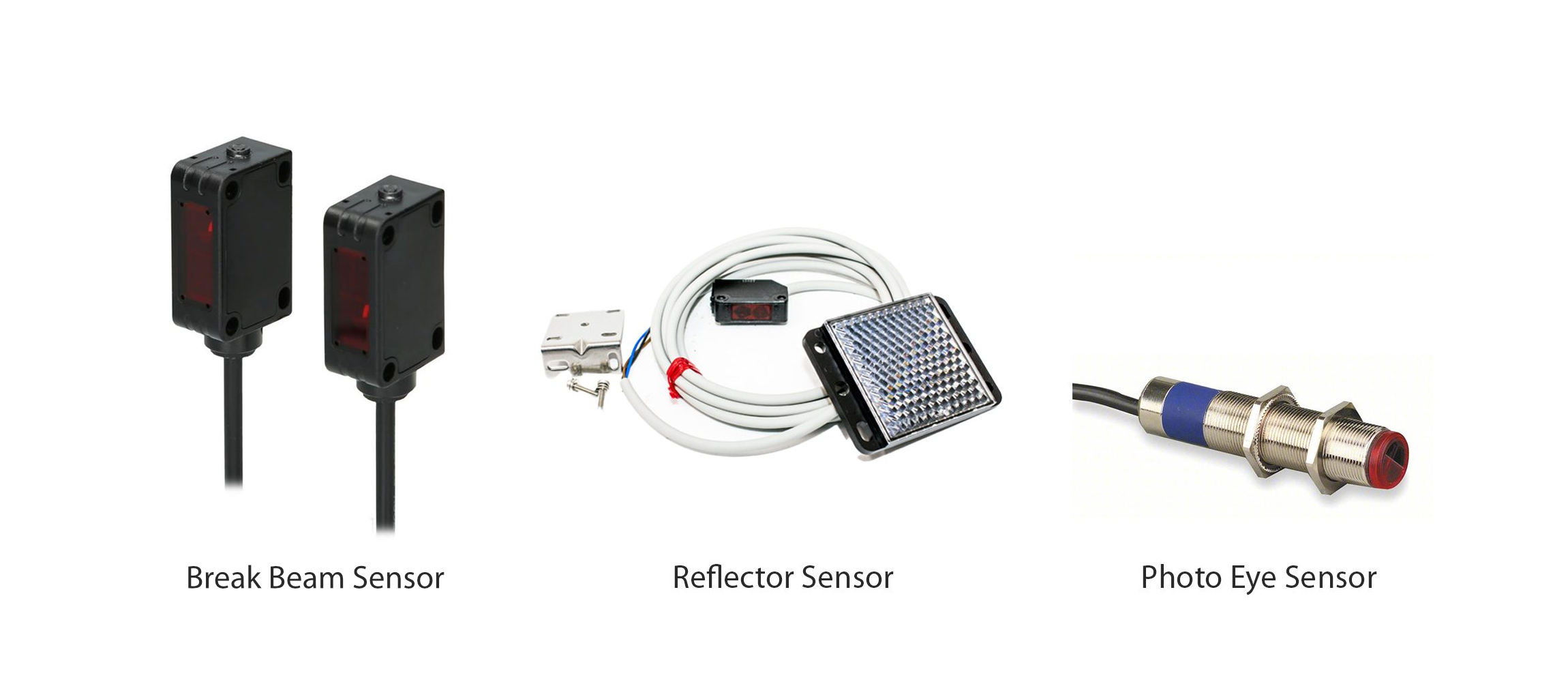
The Machine Uptime Monitor is a device specifically designed to track machine and production uptime in industrial settings. It is a flexible device that can be configure to observe one or more events via different input types – accelerometer, magnetometer, current sensor, break beam sensor, photo eye sensor, reflector sensor, current sensor.
It has long range wireless capabilities utilizing robust Mesh networking protocols with high level of security and network reliability. It is compact, durable and powered by long lasting batteries. Its main feature include:
Industrial Grade Machine Uptime Monitoring
Measure Production Uptime
Measure Number of Cycles
Dry Contact Closure Input
Wet Contact Closure Input
Acceleration Motion Detection based Uptime calculator
Magnetic Field Detection based Uptime calculator
Current-based Uptime calculator
Encrypted Communication with 2 Mile Wireless Range
Operating Temperature Range -40 to +60 °C
Humidity Range 0-90%
Wall-Mounted or Magnet Mounted IP65 Rated Enclosure
For Indoor and Outdoor Use
Many Gateway and Modem Options Available
Figure 1: Device Overview
Status LED
The Status LED is used to indicate errors or other sensor diagnostics.
LED blinks once – Message was sent successfully and no error in last sensor read as well in data transmission.
LED blinks twice and then one more time – Message was sent successfully but there was an error in last sensor read.
LED blinks thrice – MCU is having issue communicating with the radio module.
Sensor Specifications
Specifications
Minimum
Nominal
Maximum
Notes
Width
3.54"
Length
4.52"
Height
2.16"
Enclosure Rating
IP65, NEMA 1,2,4,4X,12,13, UL-508
Temperature Rating
-40° C
23° C
85° C
Component Rating
Tested Temperature
0° C
23° C
40° C
As Tested by NCD Staff
Probe Operating Temperature
-40° C
23° C
85° C
As Tested by NCD Staff
Inputs
Digital, Acceleration, Magnetic, Current
Opto-input Voltage
3.3 V
24V
Reporting interval
5 seconds
600 seconds
16777215 seconds
How often data is transmitted wirelessly
Range of counter values
1
4294967295
The maximum number of events the sensor can count to
CT Current
1.5% FS
FS
Minimum current read by the CT. CT range 100 to 1000Amp
Printed Circuit Board Specifications
Parameter
Minimum
Nominal
Maximum
Notes
Trace Width
0.007 inch
0.012 inch
0.25 inch
Trace Width depends on the Trace Type
Layer Count
2L - Rigid
Top and Bottom Layer
Material Type
FR-4 TG170
FR-4 TG170
FR-4 TG180
Surface Finish
ENIG 2u"
IPC Standard
IPC CLASS 2
Finished Copper Foil
1.0/1.0 OZ
Finished Thickness
0.062 inc
Fine line <4.0/4.0mil
No
Blind & Burried Vias
No
Non-Conductive Resin
No
Conductive Resin
No
Mechanical Drawing
Figure 3: Mechanical Drawing
RF Module Specifications
Parameter
868MHz
900MHz
2.4GHz
Frequency Band
863 MHz to 870 MHz
902 to 928 MHz
ISM 2.4 GHz
Transmitter Power
Up to 13 dBm ERP
Up to 24 dBm
Up to 8 dBm
Receiver Sensitivity
-106 dBm at 80 Kbps
-101 dBm at 200 Kbps
-103 dBm at 250 Kbps
Range (dense urban)
~1000ft
~1000ft
~300ft
Range (line of sight)
~2 miles
~2 miles
~1 mile
Data Rate
80 Kbps
200 Kbps
250 Kbps
Networking Protocol
Digi XBee® DigiMesh®
Digi XBee® DigiMesh®
Digi XBee® DigiMesh®
Encryption
128-bit AES
128-bit AES
128-bit
Reliable Packet Delivery
Retries/acknowledgements
Retries/acknowledgements
Retries/acknowledgements
IDs
PAN ID and addresses, cluster IDs and endpoints (optional)
PAN ID and addresses, cluster IDs and endpoints (optional)
PAN ID and addresses, cluster IDs and endpoints (optional)
Certification
CE/RED, ROHS Compliant
FCC (America), IC (Canada), C-Tick (Australia), Anatel (Brazil), IDA (Singapore)
FCC (America), IC (Canada), RCM (Australia), Anatel (Brazil), Teleck MIC (Japan), KCC (South Korea)
Probes Specifications
There are 4 types of probes: Bare wire for digital inputs, Current sensor, Accelerometer, and Magnetometer.
Digital Inputs
The Industrial Digital Input and Sensor Reader is a compact and robust device tailored to interpret signals from various digital inputs and sensors prevalent in industrial settings, including brake beam sensors, photo reflectors, photo eye sensors, and on/off signals. It can also work with counter with a digital pulse outputs to easily integrate with existing equipment in production lines or plants for example.
With high accuracy and reliability, it offers real-time data acquisition and monitoring, seamlessly integrating into existing industrial automation systems. Its user-friendly interface and flexible configuration options ensure easy setup and compatibility with diverse applications, enhancing operational efficiency, equipment reliability, and production optimization. Ideal for conveyor systems, packaging machinery, and robotic systems, it empowers industrial operators with streamlined data interpretation and control capabilities, minimizing downtime and maximizing productivity.
Note!When using the Photo Eye or Break Beam sensor you need to use external power as they are not powered via the batteries. Such use cases need to use the sensor where it can be powered by mains.
Click to Expand
Click to Expand
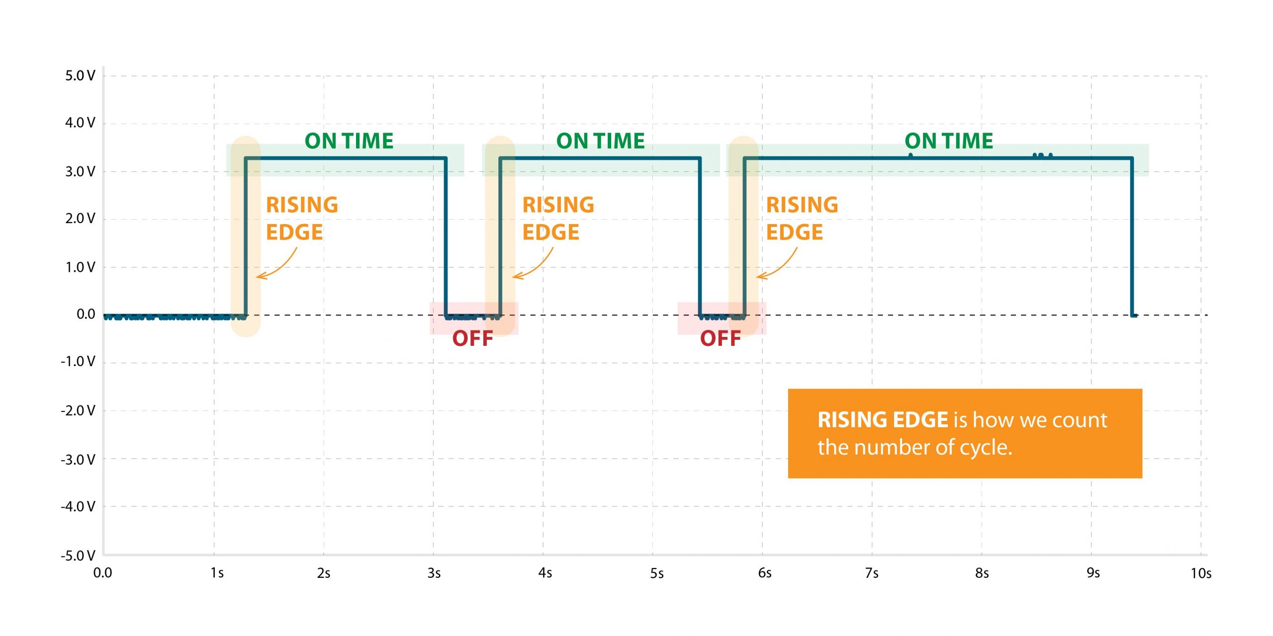
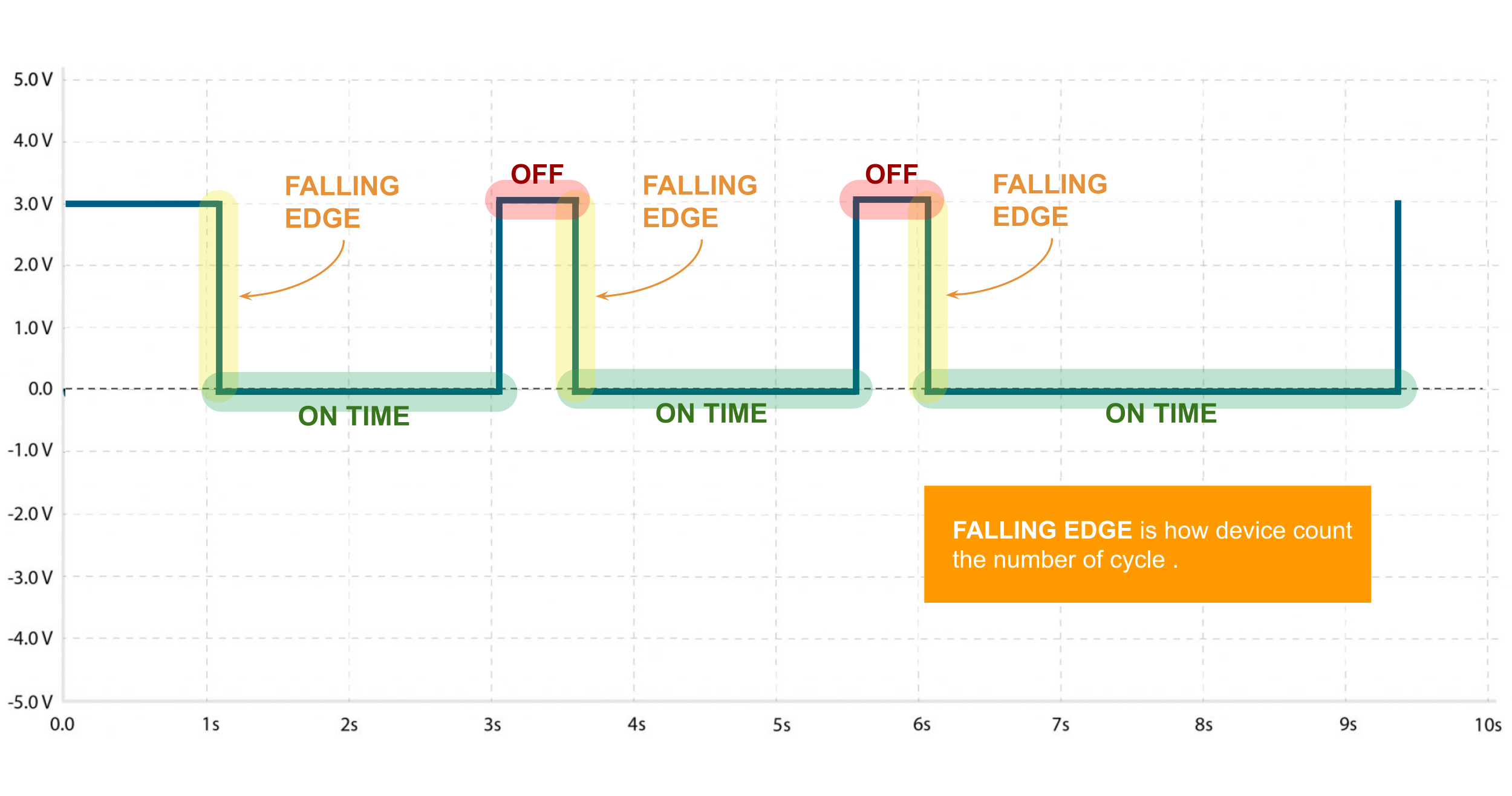
Note!When using a digital input sensor the Rising edge of the pulse is used for the cycle count by default, however you can configure it to be a falling edge instead (via software configuration of the sensor).
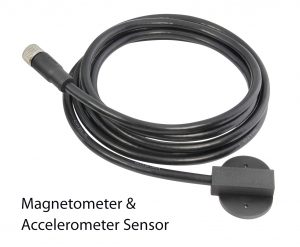
Accelerometer Sensor
The Cycle and Uptime Tracker is an innovative device engineered to monitor and record the number of cycles and total uptime of machinery or equipment in industrial environments. Leveraging advanced acceleration sensing technology, users can set customizable acceleration thresholds to precisely detect cycle initiations. This allows for accurate tracking of machine activity while minimizing false readings. The device captures and stores data, providing insights into equipment usage patterns and overall uptime. With its user-friendly interface and customizable settings, operators can easily configure acceleration thresholds to suit specific machinery requirements. Ideal for diverse industrial applications, the Cycle and Uptime Tracker enhances maintenance planning, optimizes production scheduling, and improves operational efficiency.
Magnetometer Sensor
Magnetic Field-Based Machine On/Off Detection System is meticulously engineered to precisely discern the operational status of machinery that emits magnetic fields during operation. Employing cutting-edge magnetic field sensors, this system offers unparalleled accuracy in identifying whether the machine is active or inactive. With its robust design and reliable performance, there’s no need for user adjustments, ensuring hassle-free operation. Real-time monitoring capabilities enable proactive maintenance planning and energy conservation, enhancing operational efficiency. Seamlessly integrating into various industrial setups, this system represents a pinnacle of reliability and professionalism in machine monitoring solutions.
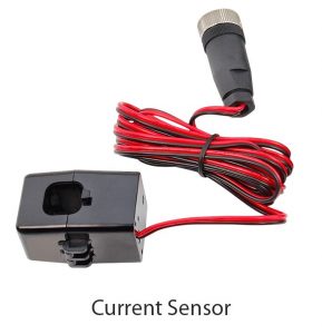
Current Sensor
Industrial Machine Uptime and Cycle Counter, a cutting-edge solution that accurately measures total machine uptime and cycle counts using advanced current sensor technology. With real-time monitoring and seamless integration, our device enables proactive maintenance planning, enhances operational efficiency, and provides valuable insights for informed decision-making. Upgrade your industrial operations with precise tracking and analysis capabilities for optimized performance and cost savings.
Note!There is a potentiometer on the PCB that you can adjust the current it takes to register an event. This allows you to properly configure the current sensor so it accurately counts cycles for your specific equipment.
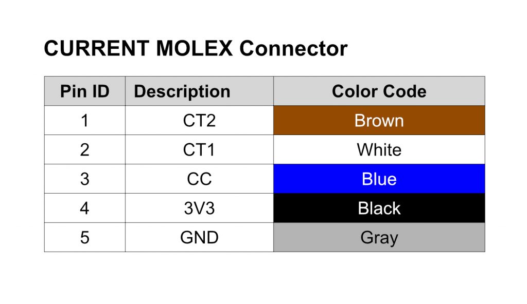
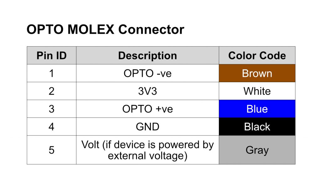
Probe Configuration and Wiring
Warning!Make sure you wire you probe correctly as per the instruction below, otherwise you risk damaging the probe and/or the sensor.
Pin Definition
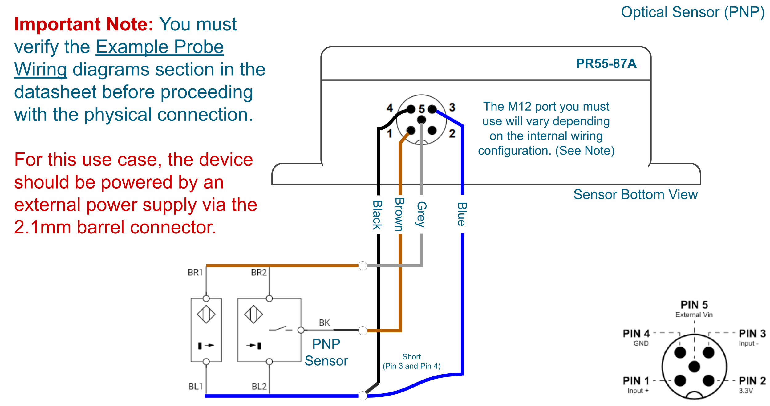
Diagram Examples
Optical Sensor (PNP)
Click to Expand
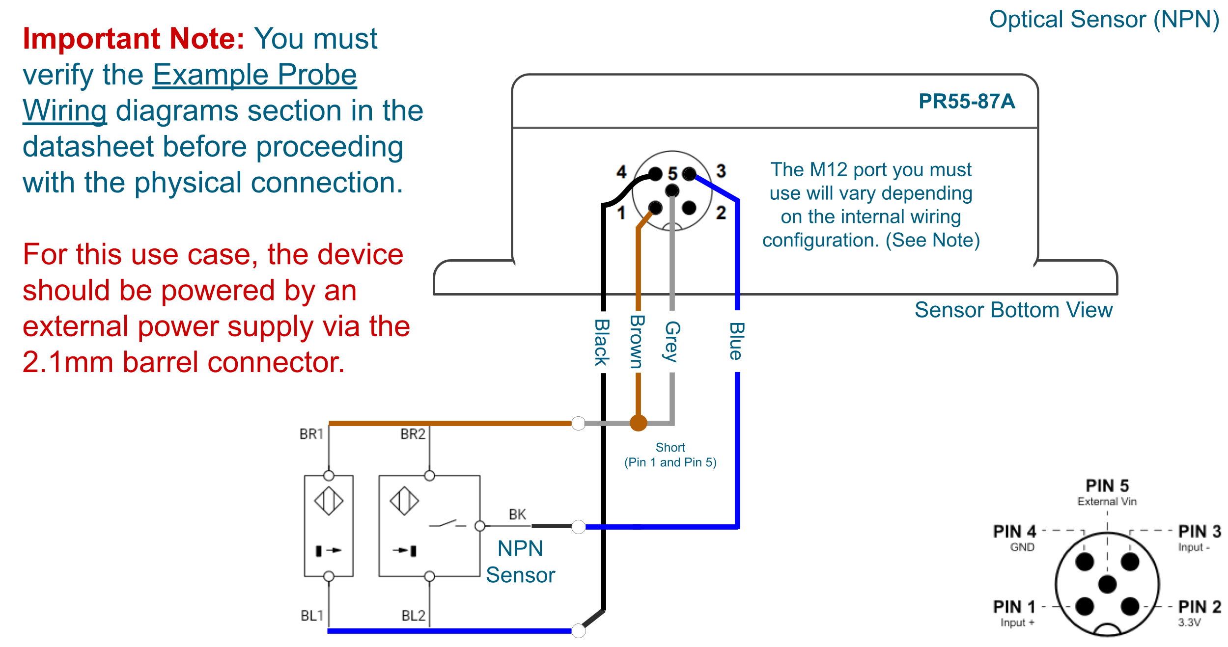
Optical Sensor (NPN)
Click to Expand
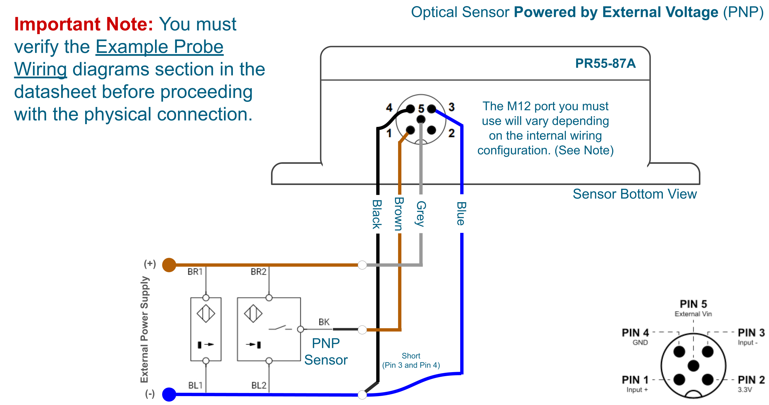
Optical Sensor Powered by External Voltage (PNP)
Click to Expand
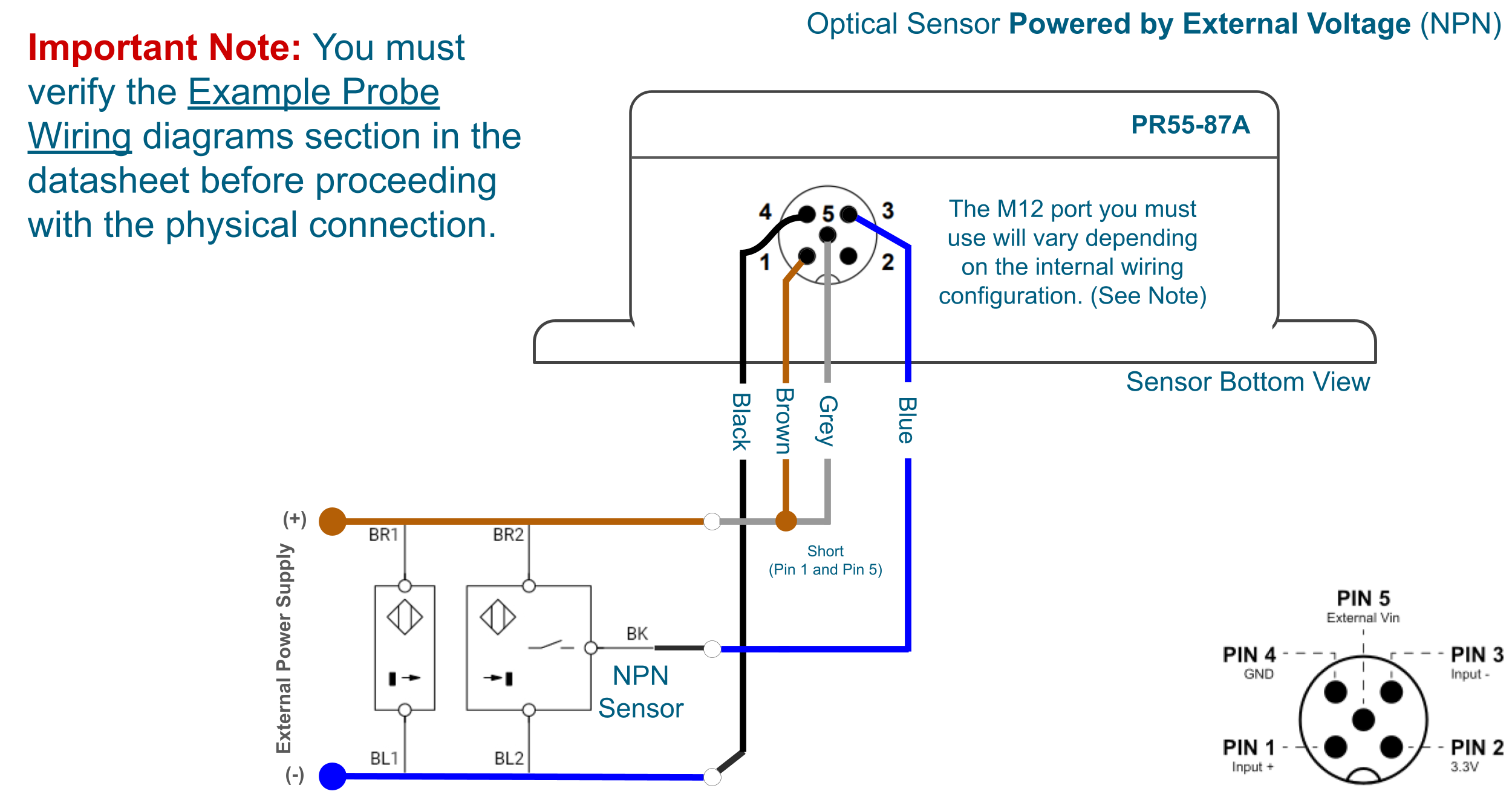
Optical Sensor Powered by External Voltage (NPN)
Click to Expand
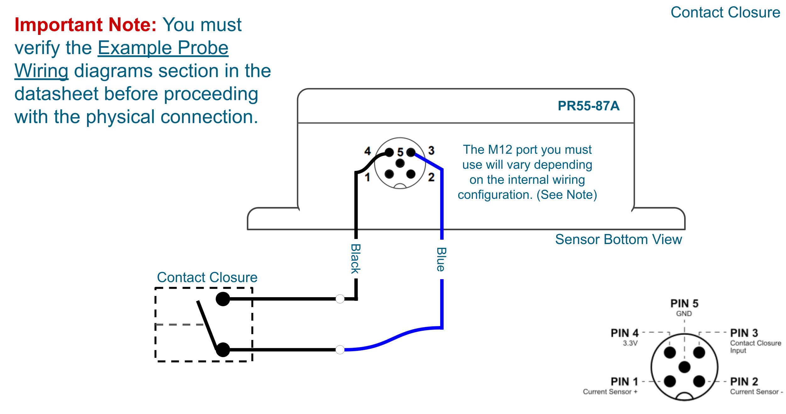
Contact Closure
Click to Expand
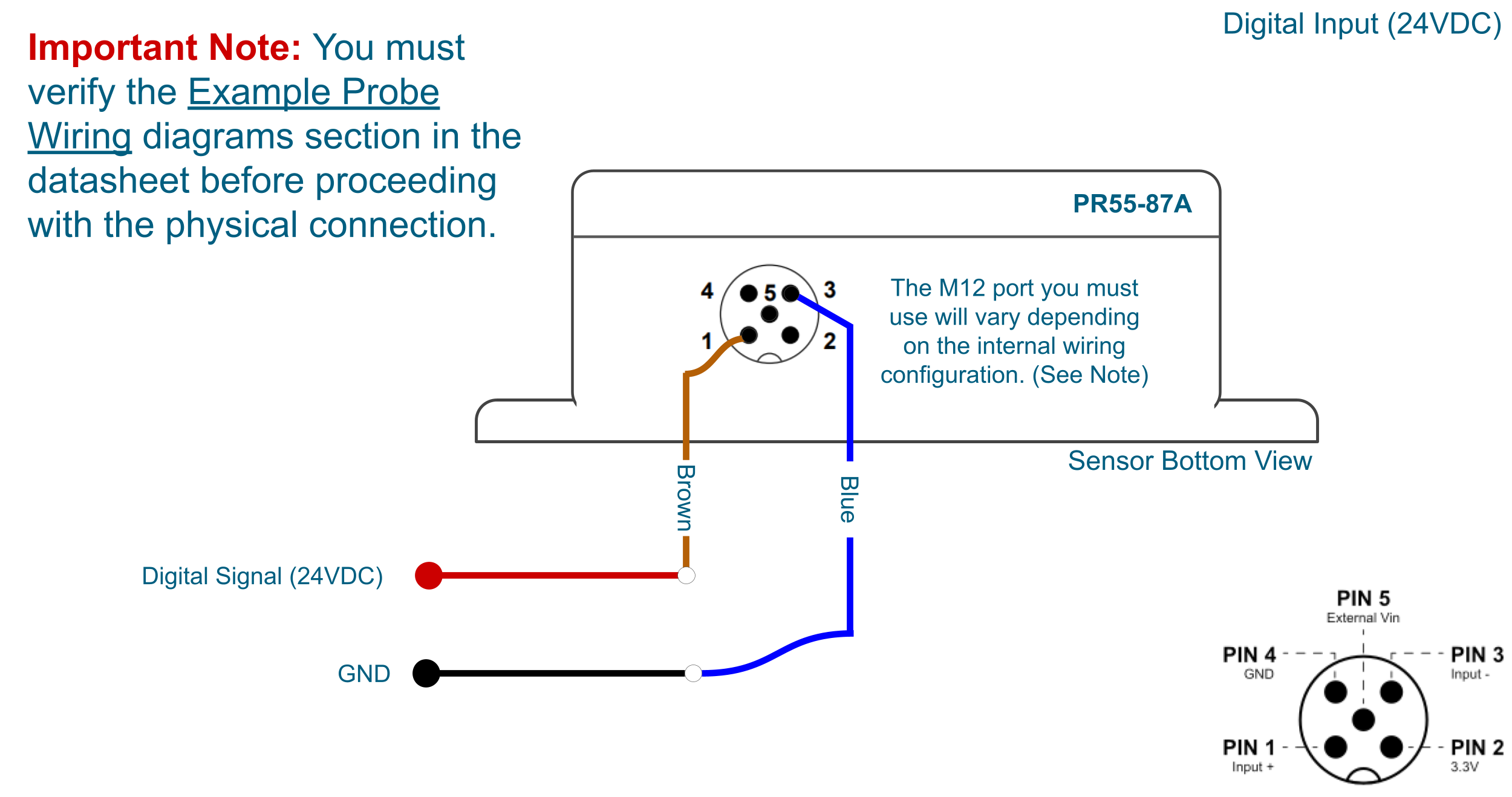
Digital Input (24VDC)
Click to Expand
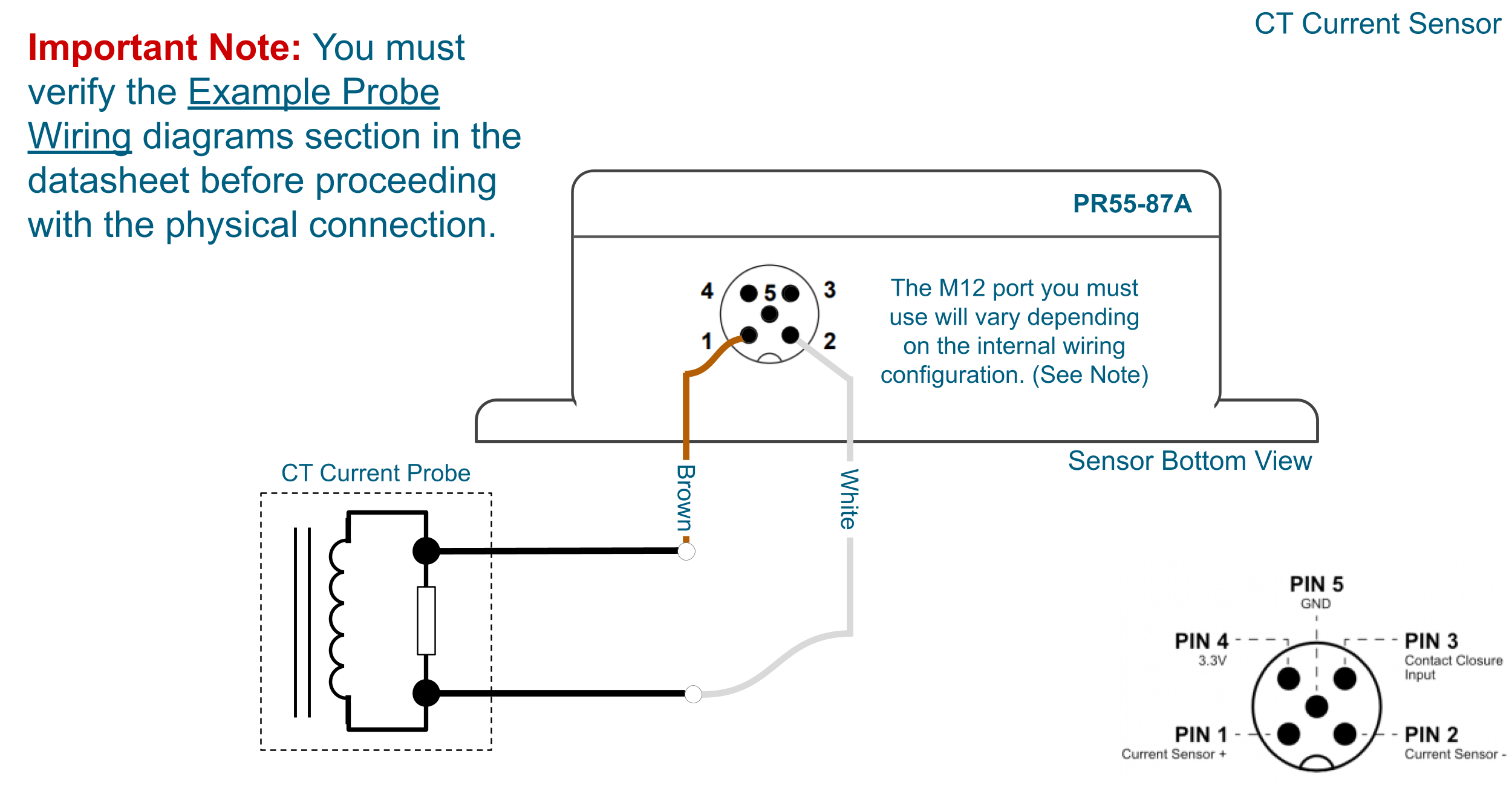
CT Current Sensor
Click to Expand
Example Probe Wiring
Depending on which probe configuration you chose you would gave to reroute the internal cabling between the M12 connector and the respective connector on the PCB. The images below show 4 example configurations.
Current Sensor + Contact Closure Input + Optical Sensor/Digital Input
Power Requirements and Expected Battery Life
Power Requirements
This Sensor has two power options:
Powered by AA batteries (NCD recommends Energizer L91 batteries)
External power supply (5-12 V DC) Current Requirement 250 mA
Note!The L91 Batteries are non-rechargeable Li-Ion batteries.
While changing the batteries:
Turn off the sensor
Only use new L91 batteries
Checkout the polarity marking on the battery holder and batteries
Replace all six batteries with new L91 batteries. Do not mix old and new batteries
Batteries should not be replaced in fire-risky areas
Do NOT install rechargeable batteries
Note!If these Devices are being used with photo eye or any other sensors needing power, use an external power supply.
Expected Battery Life
Specifications
Minimum
Nominal
Maximum
Notes
Batteries
2
6
6
May be Powered by 2 or 4 AA Batteries
Battery Life 1 TPD (Transmissions per Day)
10 Years
Estimation is based on a 30 minute interval
Battery Life 12 TPD (Transmissions per Day)
8 Years
Estimation is based on a 30 minute interval
Battery Life 24 TPD (Transmissions per Day)
5 Year
Estimation is based on a 30 minute interval
Battery Life 96 TPD (Transmissions per Day)
3 Year
Estimation is based on a 30 minute interval
Note!The Truth About Battery Life
Under the best of circumstances, the best non-rechargeable batteries commonly available today are limited to a 10 year non-working shelf life in a room temperature environment. Factors such as actual usage, temperature, and humidity will impact the working life. Be wary of any battery claims in excess of 10 years, as this would only apply to the most exotic and expensive batteries that are not commonly available. Also note that most battery chemistries are not rated for use in extreme temperatures. NCD only uses the best Non-Rechargeable Lithium batteries available today, which are also rated for use in extreme temperatures and have been tested by our customers in light radioactive environments. Lithium batteries offer a 10 year maximum expected shelf life due to limitations of battery technology. NCD will never rate sensor life beyond the rated shelf life of the best batteries available today, which is currently 10 years.