- Overview
- Main Features/Functionalities
- Applications
- Detailed Specifications
- Power Requirements and Expected Battery Life
- Getting Started
- Advanced Configuration
- Troubleshooting
- Appendix A - Command Structure and Cheat Sheets
- SET Command Cheat Sheet
- GET Command Cheat Sheet
- System Command Cheat Sheet
- Appendix B - Example SET commands
Appendix C - Example GET commands
Appendix D - Example System commands
- Industrial Grade LPWAN IoT Sensor
- Resolution of 0.01°C / 0.01%RH
- Accuracy of ±0.1°C / ±1.0%RH
- Sensor Probe Operating Temperature Range: -40 to +125ºC / -40°F to 185°F
- Sensor Probe Operating Humidity Rating up to 0 – 100%RH
- Wall-Mounted or Magnet Mounted IP65 Rated Enclosure
- Up to 2 Miles of range in Urban environment and 10+ Miles of range in an open environment (Line of Sight – LoS)
- Platform agnostic – Microsoft® Azure®, Losant, Loriot, AWS IoT Core, Helium, TTI/TTN
- Compliant with LoRaWAN® 1.0.4
- Power-Efficient Sleep Mode, Up to 10 Years Battery Life
- User Configurable Sleep duration
Overview
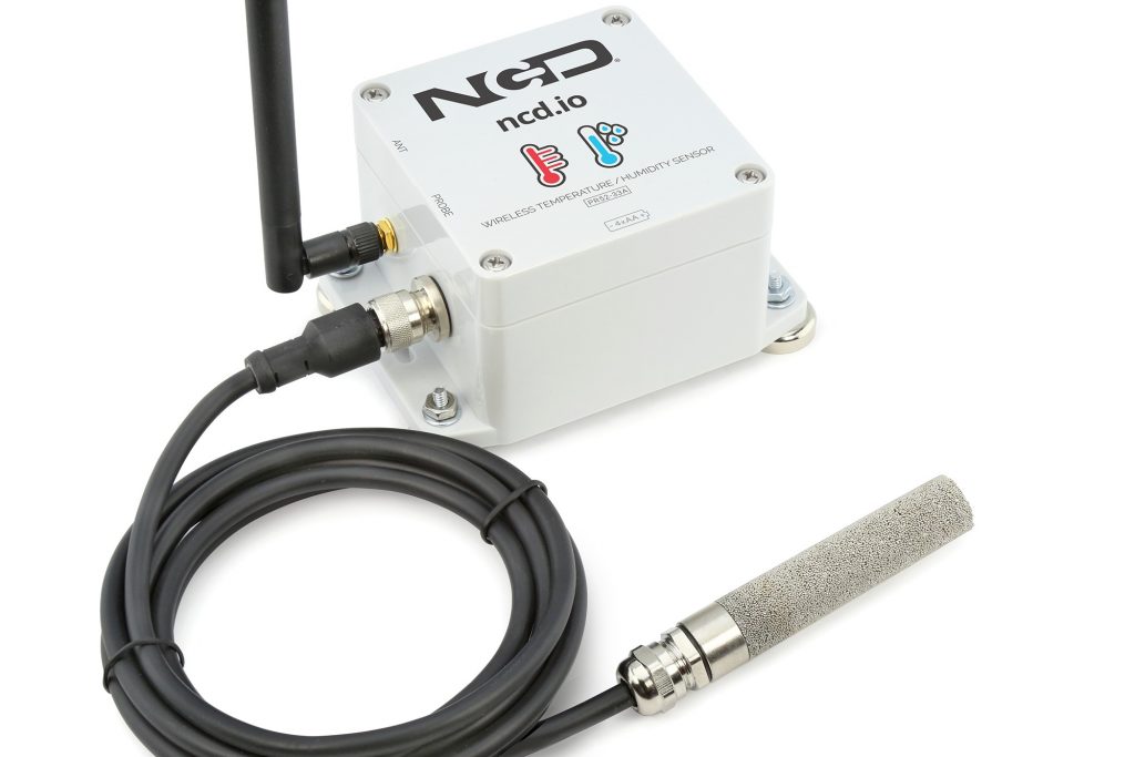
Introducing NCD’s first LPWAN node. This device features LoRaWAN 1.0.4 compatibility providing up to 2 miles range in dense urban environment and 10+ miles range in an open environment.
This sensor incorporates a precision Sensirion SHT45 Temperature and Humidity Sensor and a transceiver that sends data at user-defined intervals. This IoT Temperature Humidity Sensor goes into deep-sleep mode between transmissions to minimize power consumption and prolong battery life.
Incorporating a highly accurate (±0.1°C ±1.0%RH) temperature humidity sensor, the node send keep-alive packets of temperature and humidity data at user-defined intervals. The on-board IoT Temperature Humidity Sensor is rated for -40°C to 125°C or -40°F to 185°F.
The device is powered by just 4 AA batteries (included), you can expect to achieve up to 10 years of battery life depending on environmental conditions and the transmission interval you choose.
The NCD LoRaWAN Temperature and Humidity Sensor has one of the longest ranges, highest accuracies, longest battery lives, and best build quality on the market today and it comes at a very competitive price.
Main Features/Functionalities
0.01°C / 0.01%RH Resolution:
Resolution is a metric that describes how small of a change of the measured metric it can distinguish. This directly translate to how fine the granularity of the measurements it, in other words how sensitive the device is to changes in the environment (in this case changes in temperature and relative humidity). Industrial applications tend to be more demanding when it comes to resolution, compared to general ones. As a rule of thumb temperature resolution below 0.1°C and relative humidity of below 0.1%RH is considered a measure of a good sensor. With its 0.01°C / 0.01%RH resolution the NCD sensor satisfies even the most stringent requirements (Critical and specialty applications), going beyond what the general industrial application requires.
±0.1°C ±1.0%RH Accuracy
This is a measure of how close the provided measurement data is to the actual value of the temperature / humidity. A low accuracy means introducing a relative large measurement error, which might provide data that is not correct leading to wrong decisions, or critical failure. Industrial applications require temperature accuracy beyond ±2°C and humidity accuracy of at least 5%RH. The NCD sensor is capable of a lot more, making it suitable not only for general industrial applications, but also precision level scenarios.
-40 to 125ºC Temperature and up to 100% Humidity Operating range:
The wide range of operating temperature and the high upper limit for humidity make the sensor suitable to operate in diverse environments. Industrial settings tend to have operating conditions that are a lot more extreme than residential ones, thus a higher decree of reliability is required at a higher level of performance. This makes the device more practical as it can be utilized in opposing environments, for example the same sensor would work equally as good in a freezer or in an engine (excessive head from motor) or a or boiler room. This simplifies network deployments as you only need one device, which makes it quicker to deploy and easier to manage.
Low Power Wide Area Network support (LPWAN) utilizing LoRaWAN®:
When it comes to wireless sensors, the range is an essential parameter (together with battery life and accuracy/resolution). If you want to upgrade a facility with wireless environmental monitors, you job will be a lot easier if you choose a technology that can provide you with a stable, interference-resistant link over as large a distance as possible (this ensures you have sufficient link budget margin in case of heavy attenuation as in dense walls and metal structures). LoRaWAN® is one of the best out there in this regard. The default Frequency plan is FSB6.
Configuration mode:
Over-the-air (OTA) configuration via downlink messaging. You can configure all parameters relevant to the devices operation via a set of commands that are sent in real time. You can change network related settings such as Transmission interval, Node ID, Data Rate, Frequency band etc. This gives you full control over the sensor and eliminates the need of on-site configuration in order to save up time. A complete set of APIs is provided as reference to command structure (see Appendix A).
Platform agnostics, you own your data:
This sensor does not require the utilization of a specific platform. It utilizes an open communication protocol and can be used with any platform / vendor, provided one adheres to the LoRaWAN protocol data structure. You can interface it with a number of LoRaWAN Network Servers (LNS), like Microsoft® Azure®, Losant, Loriot, AWS IoT Core, Helium, TTI/TTN. As NCD provides a complete set of APIs that you can use for configuration and data parsing you can integrate your LNS with any post-processing platform. For example you can utilize it together with a generic MQTT broker to push the data to your server, send it to an HTTP endpoint, utilize open tools like Node-RED, Grafana, etc. for data post processing.
Confirmed / Unconfirmed mode.
This LoRaWAN device can send both unconfirmed and confirmed messages. Using confirmed mode you can increase reliability and make sure data integrity is preserved in case of applications where date delivery is critical. In case you want to optimize network capacity and emphasize on limiting network congestion you can use unconfirmed packets (suitable for applications that transmit often and packet loss is permissible).
Industrial quality enclosure (IP65 rated):
Suitable for harsh environments, where ingress protection is required. Most industrial applications which this sensor has been designed for work in harsh conditions, outdoors perhaps. The presence of dusty, rain, oil, etc. is command and the casing of the device needs to seal tight in order to no allow any damage/reduced functionality to befall the sensor due to these harsh operation environments. This makes the sensor suitable for use cases such as oil rigs, dig sites, factories, HVAC towers on top of high buildings, etc.
Power-efficient Built-in Deep-sleep mode:
This is essential for any good wireless, battery-powered IoT sensor. As the device performs readings over a regular time interval there is a significant time period where it is neither measuring, nor transmitting data. In most cases the bulk of the operational time of the device it is essential for it to consume as little power as possible. An efficient sleep mode guarantees that the sensor squeezes the best battery life possible, as it turns down the current consumption by switching off all of the clocks and sensors in order to preserve power, unless an interrupt is received. This is part of the firmware and one only need set the wake-up interval, the device takes care of the rest.
As a result the user can best balance between device battery longevity and the granularity of the sensor measurements that best suits their use case. A battery life of up to 10 years is possible with 4xAA batteries (see battery life reference table for details).
Applications
Storage Unit Environmental Monitoring System:
Battery powered sensor devices as the NCD LoRaWAN Temperature and Humidity Sensor are perfect for integrating into small storage units. For example one could monitor the environment into a medical supply cabinet to make sure medicine is stored at the appropriate condition in order to void them expiring ahead of time. By constantly monitoring Temperature and Humidity and setting up alarms you can make sure you are notified immediately if there is a critical need of adjusting the environmental conditions. As the device is small and there is no need for mains power, it is easy to integrate in small spaces and it requires no remodeling of the cabinet or storage unit to integrate it.
Detailed Specifications
Device Overview
Printed Circuit Board Specifications
| Parameter | Minimum | Nominal | Maximum | Notes |
|---|---|---|---|---|
| Trace Width | 0.007 inch | 0.012 inch | 0.25 inch | Trace Width depends on the Trace Type |
| Layer Count | 2L - Rigid | Top and Bottom Layer | ||
| Material Type | FR-4 TG170 | FR-4 TG170 | FR-4 TG180 | |
| Surface Finish | ENIG 2u" | |||
| IPC Standard | IPC CLASS 2 | |||
| Finished Copper Foil | 1.0/1.0 OZ | |||
| Finished Thickness | 0.062 inc | |||
| Fine line <4.0/4.0mil | No | |||
| Blind & Burried Vias | No | |||
| Non-Conductive Resin | No | |||
| Conductive Resin | No |
Sensor Specifications
| Parameter | Temperature | Humidity |
|---|---|---|
| Resolution | 0.01°C | 0.01%RH |
| Accuracy | ±0.1°C | ±1.0%RH |
| Operation Range | -40 to +125ºC | 0 to 100%RH |
| Storage Range | -40 to +150ºC | - |
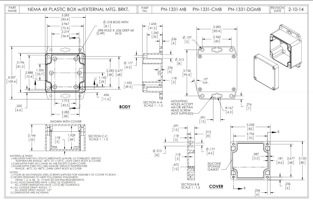
Mechanical Drawing
Power Requirements and Expected Battery Life
Power Requirements
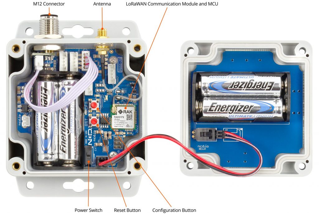
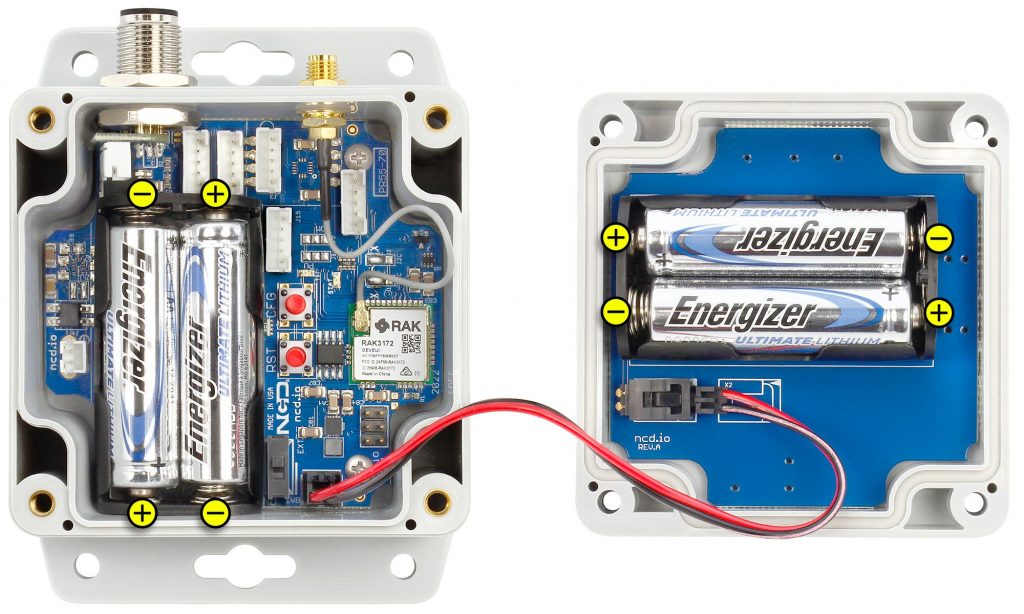
This Industrial IoT Wireless Transmitter uses four AA batteries, two are on the main circuit board and the other two are installed on the back of the top lid.
Please note, the L91 batteries are non-rechargeable Li-Ion batteries. During the battery replacement process, adhere to thefollowing guidelines:
1. Switch off the sensor before initiating the battery change.
2. Always use NEW Energizer L91 Lithium batteries.
3. Observe the polarity markings on both the battery holder and batteries to ensure correct installation (refer to the image below).
4. Replace all four batteries simultaneously; mixing old and new batteries is not recommended. To reduce the risk of explosion do not mix old and new batteries or batteries from different manufacturers.
5. Avoid changing batteries in areas where there’s a risk of fire.
6. Rechargeable batteries are not suitable for this device.
7. Batteries are installed in 2S2P Configuration.
Power Ratings:
Maximum power usage during data transmission is 300mW.
Power consumption during sleep or idle operation is minimal, at 0.165mW.
Note: If Batteries are installed backwards, batteries will discharge safely through built-in fuses and the user will experience a very short battery life. Care should be taken to install batteries correctly for maximum battery life.
Expected Battery Life
Most NCD IoT Sensors are rated for 300,000 to 500,000 transmissions until the batteries become so weak they are unreliable. You could spread these transmissions out over a 10 year period and send 50,000 transmissions per year. This would allow up to 136 transmissions per day, or about 5 transmissions per hour (for a 500K sensor, or 3 per hour for 300K sensor). If you only need the batteries to last 3 years, you could send 166,666 transmissions per year, or about 456 transmissions per day (about 19 transmissions per hour for a 500K sensor). As you can see, battery life is really up to you. By altering advanced settings in the NCD IoT sensor, you have control over longevity. Please note the 500,000 transmission rating is for premium alkaline batteries. NCD ships all sensors with premium Lithium batteries, which include a ultra-wide temperature range that typically lasts in excess of 600,000 transmissions for some sensor types. These batteries weigh less than half of alkalines, and they work in the freezer! A word of caution though, putting a sensor in configuration mode will drain the batteries very quickly. It’s important to configure your sensors and exit configuration mode as soon as possible or use a external power supply during configuration (if supported by the sensor). The table below indicates how many Transmissions Per Hour (TPH) your can expect from different sensors over a lifespan of up to 10 years.
| Battery Life | 3 Months | 6 Months | 1 Year | 2 Year | 3 Year | 5 Year | 10 Year |
|---|---|---|---|---|---|---|---|
| 300K Sensors | 136 TPH | 68 TPH | 34 TPH | 17 TPH | 11 TPH | 6 TPH | 3 TPH |
| 400K Sensors | 180 TPH | 90 TPH | 45 TPH | 22 TPH | 15 TPH | 9 TPH | 4 TPH |
| 500K Sensors | 228 TPH | 114 TPH | 57 TPH | 28 TPH | 19 TPH | 11 TPH | 5 TPH |
| 600K Sensors | 272 TPH | 136 TPH | 68 TPH | 34 TPH | 22 TPH | 13 TPH | 6 TPH |
The Truth About Battery Life
Under the best of circumstances, the best non-rechargeable batteries commonly available today are limited to a 10 year non-working shelf life in a room temperature environment. Factors such as actual usage, temperature, and humidity will impact the working life. Be wary of any battery claims in excess of 10 years, as this would only apply to the most exotic and expensive batteries that are not commonly available. Also note that most battery chemistries are not rated for use in extreme temperatures. NCD only uses the best Non-Rechargeable Lithium batteries available today, which are also rated for use in extreme temperatures and have been tested by our customers in light radioactive environments. Lithium batteries offer a 10 year maximum expected shelf life due to limitations of battery technology. NCD will never rate sensor life beyond the rated shelf life of the best batteries available today, which is currently 10 years.
Getting Started
Pre-requisites
This is a LoRaWAN® compatible device, thus it requires a LoRaWAN® gateway within range to receive and forward packets to the LoRaWAN Network Server (LNS). Furthermore, in order for the packets to be received and successfully decrypted it needs to be registered with the aforementioned LNS.
The example in this document utilizes The Things Industries (TTI) stack. You can alternatively use its public version The Things Network (TTN), the differences in the registration procedure are negligible. The document assumes you have created an account already.
You can find more about TTI/TTN and how to register here:
Default Configuration
The node comes pre-configured with a set of LoRaWAN® keys which you can use to onboard it via your preferred choice of LNS. This document will use TTI/TTN as example.
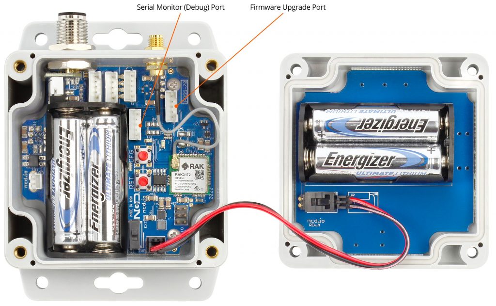
As an alternative you can obtain the pre-coded key by connecting via a Serial to USB converter to the port shown in the image below. Once connected press on the “Reset” button for the device to reboot and it will report its configuration settings and set of LoRaWAN keys.
Note: Powering the device before registering it with an LNS is not recommended as it will repeatedly try to join, to no avail (this drains battery, fast). Do this only after you have it registered (following section) or in case you need to obtain the keys via the Serial.
Below is an example Serial report for your reference (your keys will be different and the firmware version might defer depending on time of when you read this article):
The factory default settings are as follows:
Frequency region:
US915, where FSB6 is utilized for the sub band.
Join mode:
The device works in OTAA mode by default (if you require ABP functionality contact the NCD team)
ADR mode:
ADR is turned on by default, if your LNS supports it we recommend you use it with this feature, unless the node is mobile (should not be the case for this type of node in general).
Confirmed / Unconfirmed mode:
By default, it is sending confirmed uplinks. Depending on your requirements for data integrity and the transmission interval you might want to adjust this. As a general recommendation we advise to use unconfirmed mode in order to reduce dwell time, battery consumption and limit network congestion.
Note: You can reset the node to its default settings with the 0x50 command via a downlink or physically. After a reset or bootup there is a 3 seconds window where you can press the CFG key inside the device and hold it for 10 seconds to reset to the factory default settings.
Registration with the LNS
Assuming you have been provisioned with the keys separately (via a CSV file from NCD) and you need not connect to the Serial port to obtain them you can follow the steeps below in order to register your device. The method where you obtain or change the keys is going to be discussed in a separate document.
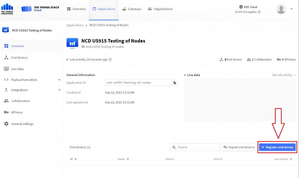
Go to your TTI/TTN account and create an application, pick a suitable name and proceed. You will see the following page where you need to press on the blue “Register end device button”.
					BOARD INIT OK
Release: Sep 12 2023
FW ver: 0x5
APP KEY
 0x2B 0x7E 0x15 0x16 0x28 0xAE 0xD2 0xA6 0xAB 0xF7 0x15 0x88 0x11 0x22 0x33 0x44
NWK S KEY
 0x2B 0x7E 0x15 0x16 0x28 0xAE 0xD2 0xA6 0xAB 0xF7 0x15 0x88 0x11 0x22 0x33 0x44
APP Session KEY
 0x2B 0x7E 0x15 0x16 0x28 0xAE 0xD2 0xA6 0xAB 0xF7 0x15 0x88 0x11 0x22 0x33 0x44
Dev Eui
 0x38 0x00 0x12 0x00 0x01 0x02 0x03 0x04
APP Initialized
SHT45 Temperature = 24.786
SHT45 Humidity = 38.478
Dev not joined
Requesting to join
Dev Joined Successfully
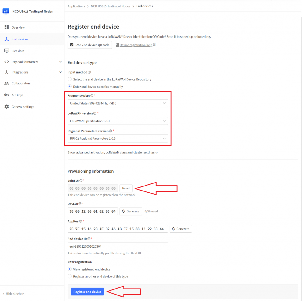
In order to properly onboard the device you have to set up the correct parameters and keys. Select the “Enter end device specifics manually” option via the Radio button. This will open up a set of drop-down menus. As you start up setting parameters more fields will open up. Eventually you should end up with a window similar to the one shown in the image below. The parameters are as follows:
Frequency Plan
United States 902-928 MHz, FSB6
LoRaWAN version
LoRaWAN Specification 1.0.4
Regional Parameters version
RPO002 Regional Parameters 1.0.3
JoinEUI
Once these are selected you will be presented with a text field to fill in the JoinEUI. Fill it out with 0s, this can be used as default for NCD test nodes. Note this parameter is not reported via the Serial as it applies to all NCD nodes at the time of writing of this document.
00 00 00 00 00 00 00 00
DevEUI
For the DevEUI enter the one provisioned by NCD (or Serial), in our example it would be:
38 00 12 00 01 02 03 04
AppKey
For the AppKey enter the one provisioned by NCD (or Serial), in our example it would be:
2B 7E 15 16 28 AE D2 A6 AB F7 15 88 11 22 33 44
Leave the reset as is and finalize the procedure by pressing the blue “Register end device” button.
At his point your device is registered with the TTI/TTN LNS and is awaiting activation (initiation of the join procedure).
Joining on Boot
The device initiates the sensors and immediately initiates the OTAA join procedure, sending a join request to the LNS (Join Server). This happens when it is powered on.
If you have the device properly registered with your LNS of choice (check the previous section). It should take less than 10 seconds for it to join.
Note: The join time of around 10 seconds applies for default FSB6 (you would also need a gateway in range that supports the sub band). If the device is working in Hybrid mode and goes over all 8 FSBs it could take significantly longer (on the order of several minutes up to an hour).
The join request packet is repeatedly sent on the uplink (with an interval of 50 seconds) until a join accept downlink is received by the device and the session is negotiated with the LNS (the keys are exchanged). It the device does not receive a valid join accept message for 10 consecutive join requests it doubles its transmission interval (100 seconds in this case). This process repeats over and over until the device joins.
If you are connected via Serial, you should see the following upon a successful power up and joining of the network.
					BOARD INIT OK
Release: Sep 12 2023
FW ver: 0x5
APP KEY
 0x2B 0x7E 0x15 0x16 0x28 0xAE 0xD2 0xA6 0xAB 0xF7 0x15 0x88 0x11 0x22 0x33 0x44
NWK S KEY
 0x2B 0x7E 0x15 0x16 0x28 0xAE 0xD2 0xA6 0xAB 0xF7 0x15 0x88 0x11 0x22 0x33 0x44
APP Session KEY
 0x2B 0x7E 0x15 0x16 0x28 0xAE 0xD2 0xA6 0xAB 0xF7 0x15 0x88 0x11 0x22 0x33 0x44
Dev Eui
 0x38 0x0 0x12 0x0 0x1 0x2 0x3 0x4
APP Initialized
SHT45 Temperature = 24.786
SHT45 Humidity = 38.478
Dev not joined
Requesting to join
Dev Joined Successfully
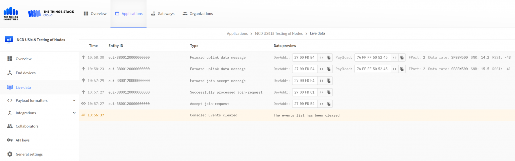
If the Device EUI and Keys in the node and LNS match upon receiving the join request the LNS will respond with a join accept. Once the node receives and processes it will establish a connection and start sending regular uplink frames over a certain pre-defined interval. At this point you should start seeing the uplinks in your LNS of choice. For the example we are using this is represented in the image below:
Advanced Configuration
Once the node has been powered on it initiates the Join Procedure. Depending on whether it is successful or not it will either back off and increase the Join Request interval, or go into Link Evaluation mode. Once the link quality has been deemed sufficient it will move to Normal Operation mode. The Link Evaluation mode is a perfect time to send downlink commands to adjust parameters before the node has started sending measurement data.
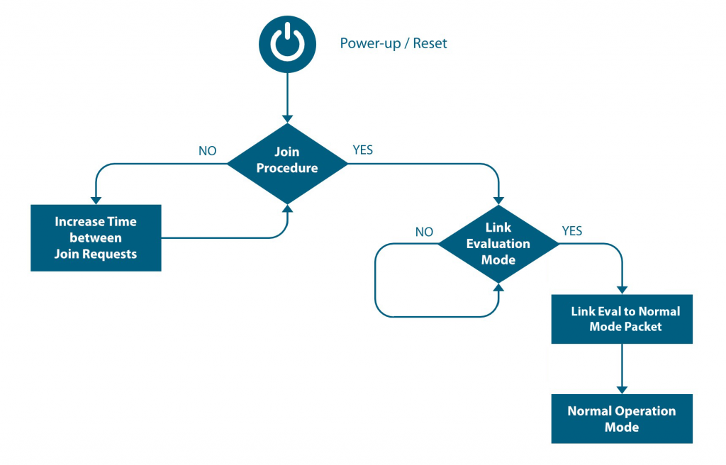
Link Evaluation Mode
This is a temporary mode and the device enters it after rejoining a network/LNS. It evaluates the wireless link based on the measured RSSI and SNR in order to ascertain that the connection is stable. Furthermore, it gives you time to send downlink commands to configure the node before it starts normal operation. The devices exits this mode once the link has been deemed stable (2 consecutive good uplink messages).
Normal Operation Mode
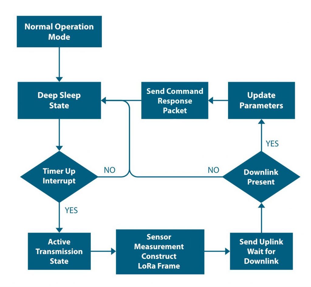
This is the default mode of operation. The device enters this mode after it successfully exits the Link Evaluation Mode. In this mode the device cycles between two states: Deep sleep and Active transmission.
Link Status Evaluation
After successfully joining, PRE Msg packets will be sent to the server to evaluate the network stability (RSSI and SNR). This will also give the LNS time to push any configuration downlinks before the sensor starts reporting measurement data. Upon receiving 2 successful acknowledgements for the Pre Msg packets the device will switch to normal operational mode.
There are the following cases to consider that are outside of normal operation:
- The node stays in this mode till 2 consecutive uplinks are acknowledge and the link quality is deemed sufficient. Until the aforementioned requirements are satisfied the node will keep sending PRE MSg pacts.
- If at any time device resets (due to button power loss for example), it’ll resume from where it stopped before resetting, configuration parameters are retained.
- As this device works in Class A by default, the server can send configuration downlinks after every uplink (this applies to any packet, whether a normal mode keep alive packet, or a Pre Msg packet, etc.).
Normal Operation Mode
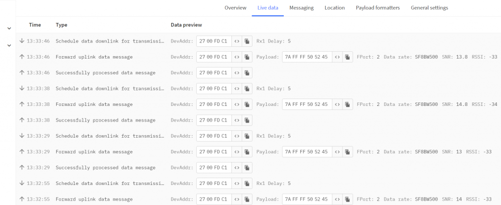
In this mode the device sends a regular keep alive uplink containing the measured parameter data. By default, this interval is 60 seconds and can be adjusted within the limitation of the LoRaWAN Duty cycle.
This is the most power efficient mode as the device goes into deep sleep when it is not sending/receiving (every 60 seconds by default). Thus, you want to stay in this mode as much as possible. The device wakes up in regular intervals, the sensors obtain measurement data, an Uplink LoRa Frame is constructed and is send via the LoRa Radio. Upon sending the packet the node awaits for a Downlink message from the LNS (if any it processes it and adjusts it parameters) and goes into deep sleep after (waking up at the next time slot).
Note: The very first packet sent in this mode, the one after switching from Link Eval mode has a specific structure that is different than regular Normal Operation mode packets. It is static in the sense that it always has the same header and payload and it carries no temperature and humidity data. The purpose of this packet is to let the application know that it has switched to Normal operation mode.
7A 01 52554E
7A – Link Eval header
01 – Device type
52554E – Normal Operation Mode payload
Automatic reboot/rejoin
Depending on how the node is configured it has a build in mechanic to rejoin the network in case connection is unstable. If the node works in confirmed mode (check Appendix B ->command 0x07) where it waits for an ACK after each uplink you can set it up to reboot and rejoin the network after a certain number of missed ACKs are registered (check Appendix B -> command 0x0D).
For example if we set the Maximum Tx Fail count to 3 via the following downlink frame F7 FFFF 01 0D 01 03, the node will send regular uplinks and if at some point for 3 consecutive uplinks the node does not receive the ACK downlink packets it will reboot and try to rejoin. It is advisable to not use too low a value for this parameter to avoid frequent rebooting.
Note!
- After passing maximum allowed failures, Node will reset and start new join session
- If node failed to transmit for more than 8 times, it’ll switch to hybrid mode “Hoping in all available channels” (Applies for US915 band only)
Large packets
It is possible in certain cases that a packet is scheduled to be sent via an uplink, however it has too large a payload to fit in a single LoRa Frame, because the Data Rate is not high enough (in case the node is using a higher SF as it is having range issues). An example would be a response to a very large set of downlink commands being queued from the server.
This event generates a special packet that replaces the normal application payload that contain in its payload the minimum Data Rate (DR) to be used in order to send the packet, for example:
7E 414C45 01
7E – Alert Packet header
414C45 – Alert payload
01 – Min data rate to be used to send requested payload
Normal Operation Mode packet structure
Once the device is in Normal Operation mode, it starts sending regular Uplink packets with measurement data in the payload. It has the following structure:
| Byte index | Bit index | Meaning |
|---|---|---|
| 1 | FW Version | |
| 2 | 7 | Reserved |
| 0:6 | Battery Voltage | |
| 3 | Reserved for Message Status | |
| 4 | Variable length |
Lets look at an example:
00 63 FF 7F 484559
00 – FW version 0
63 – Voltage
FF – Device type
7F – Reserved
484559 – Payload
Downlink command configuration
Once the node goes into Normal Operation mode, the connection is stable and it is regularly sending keep-alive packets. You can change any of the configuration settings that you want. The device is a Class A node, thus is only accepts Downlink configuration frames in a short time window after each Uplink (in this case the keep-alive), so keep this in mind, the change won’t be immediate.
You can schedule a Downlink with the appropriate payload (depending on the command you want to issue), it will be queued by the LNS and will be sent after the next Uplink frame received by the LNS.
Once the node receives the Downlink it evaluates the payload and if it corresponds to a command (if it is correct) it executes the command. This is immediately followed by an Special uplink corresponding to the exact command. The payload and header (7C) are specific and tell us whether the command was successfully implemented.
Example Downlink configuration
Let’s look at an example command (diagram below) in order to better understand how the configuration procedure works (for a full set of commands and the corresponding responses check Appendix A):
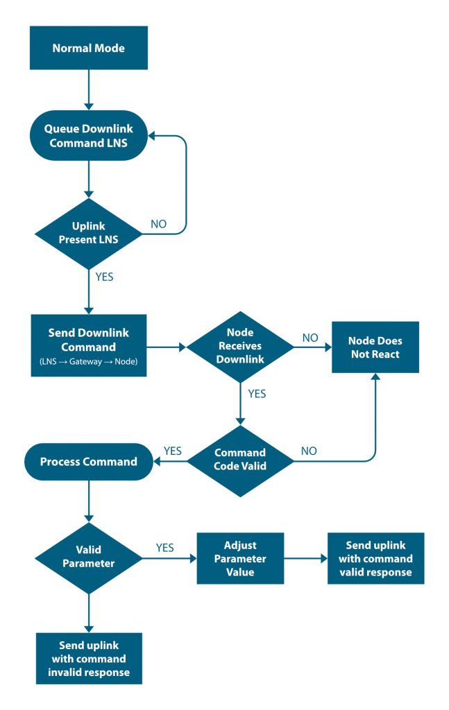
The procedure can be loosely define in 2 parts – LNS portion and Node portion.
Things start on the LNS side, where a command is queued to be sent as a Downlink packet. The server than awaits an Uplink message from the node in order to send the Downlink (as it is a class A device this is the only time it would receive it).
Once an uplink is received (any uplink would do), the server sends the downlink with the command payload (proper header, etc.) to the LoRaWAN gateway that forwards it to the node.
Assuming the node receives the packet (issues with range, power, interference could prevent it) it processes it and examines the packet payload. First it looks at the command header and determines if it is a valid one. If it is not it ignores the command, if it is it pulls the parameter value to be changed. There are two cases here.
1. The value for the parameter to be changes is outside of the allowed range for this particular parameter. In this case the node does not adjust its configuration, but sends a response to the LNS (via the gateway) with an uplink packet with an Invalid Command Payload (see Appendix A for structure). This lets you know that the command did not go through due to an error in the requested parameter change and the node did not change its configuration parameters.
2. The value for the parameter to be changes is within the allowed range for this particular parameter. In this case the node adjusts its configuration and sends a response to the LNS (via the gateway) with an uplink packet with a Valid Command Payload (see Appendix A for structure). This way the you are notified that the command has been received and the changes you requested too effect.
Command Grouping
We can group commands together and send them in one go and receive response in one go too BUT THEY MUST BE ALL OF SAME TYPE “SYSTEM COMMANDS OR APPLICATION COMMANDS” MIXING SYSTEM COMMANDS WITH APPLICATION COMMANDS ISN’T ALLOWED.
For example if we want to SET the report rate to 60s and GET the maximum allowed tx failures at the same time.
F7 02 02 04 0000003C 2C 00
F7 – System command header
02 – Number of commands
02 – SET report rate ID
04 – Parameter length
0000003C – Parameter Value (3C[HEX] = 60[DEC])
2C – GET maximum allowed tx failures ID
00 – Parameter length
Response: “If response on getter only allowed”
7C F7 2C 7F 01 10
7C – Command response header
F7 – System command header
2C – Maximum Tx fail ID
7F – Response status success
01 – Parameter length
10 – Tx Failure count
Response “ If response on all enabled”
7C F7 02 FF 00 2C 7F 01 10
7C – Command response header
F7 – System command header
02 – Set report rate ID
FF – Response status success
2C – Maximum Tx fail id
7F – Response status success
01 – Parameter length
10 – Tx Failure count
Troubleshooting
Here are some common issue one might encounter when first setting up the sensor or later on when advance configuration is performed:
1. No or low range/coverage. Data is not received by the Gateway. Make sure you have properly installed the antenna and have as little obstructions/metal surrounding the sensor. Check your LNS/Node ADR settings, if you are using a Low SF (SF7), you might want to change it to a higher one (this improves range). SF7 to SF9 are recommended in general, you can go up to SF12, but this will decrease network capacity.
2. Measurement data missing or values are inconsistent. This might be due to not installing/tightening the probe correctly. Make sure you screw it in all the way and that you position it appropriately where you want to perform the measurements,
3. In case data is not being received (was previously received) there might be a power issue. Check the batteries and or the status of the internal LEDs.
4. If there are connectivity issue where data is being received intermittently or packets are being lost, make sure that you are not in a RF heavy noise environment and/or the sensor is not positioned too far away from the nearest Gateway. You might need to install additional Gateway/s. Check if the Gateway is powered properly and operational and its antenna has been installed properly. Check whether the Gateway is properly connected to the LNS.
5. In case you still can’t solve your issue head to our Community forum to get real time help from the NCD community of experts: https://community.ncd.io/
Appendix A - Command Structure and Cheat Sheets
Depending on what mode the node is operating and what is the type of the command, there are several different payload headers. Each header has a size of 1 byte, you can find the HEX representation of each possible case below:
7A à Mode Msg Header
F7 à System Command Header
F4 à Special Command Header
7C à Command Response header (after a successful downlink has been received by the node)
7E à Alert Packet Header
Note: Some commands take effect immediately, others after you reset the node. The commands that take effect immediately are:
- Report rate setter
- Join rate setter
- Data rate setter
- Tx power setter
Below you can find cheat sheets for all commands to use as a quick reference for their command codes.
You can send a single command or 2 or more queued one after the other. You need to follow the structure for each command and also set the
Command Code -> 1byte
Parameter Length for Command 1 -> 1byte
Parameter Array for Command 1 -> variable
Command Code 2 -> 1byte
Parameter Length for Command 2 -> 1byte
Parameter Array for Command 2 -> variable
Let’s look at an example command where we Set the Report Rate and Get the Tx Power in order to understand the Command structure.
F7 FFFF 02 02 04 0000000A 28 00
F7 – System Command Header
FFFF – Device type
02 – Command count in this packet
02 – Command Code 1 for the First Command (in this case Set Report Rate)
04 – Command 1 Parameter Length (in this case the Set Report Rate command has a 4 byte length
0000000A – Command 1 Parameter Value (in this case 0x0A[HEX]=10[DEC] -> report every 10 seconds)
28 – Command Code 2 for the Second Command (in this case Get TX Power)
00 – Command 2 Parameter Length (in this case it is 0 as this is a Get Command and they have no parameters to set, thus no Parameter Value follows either).
SET Command Cheat Sheet
| Command Code [HEX] | Payload Length [Bytes] | Description |
|---|---|---|
| 0x02 | 4 | Set Report Rate (the time between 2 consecutive keep alive packets) |
| 0x03 | 1 | Set Frequency Group (Select the LoRaWAN FSB) |
| 0x04 | 1 | Set App Port (set the Fport for the uplink packets) |
| 0x05 | 1 | Set Cfg Port (set the Fport for the downlink packets) |
| 0x06 | 1 | Set Adaptive Data Rate mode (0 – off, 1 – on) |
| 0x07 | 1 | Set Confirmed Mode (0 – off, 1 – on) |
| 0x08 | 1 | Set Uplink Data Rate (DR) (available DR0 – DR4) |
| 0x09 | 1 | Set Tx power (20dBm max) |
| 0x0A | 4 | Set Join Retry rate (in seconds) |
| 0x0B | 1 | Set Stable connection maximum fail count (default is 2) |
| 0x0C | 4 | Set Stable connection msg rate (in seconds) |
| 0x0D | 1 | Set maximum Tx Fail count. Tx Fail count = 8(const) + 16(default) = 24. The user can only change the second value, with a minimum of 16, thus the lowest possible value is 24. If the user wants to have a count of 30 they need to set the parameter to 22. |
| 0x0E | 1 | Set maximum Join Fail count |
| 0x0F | 1 | Allow Setter response |
GET Command Cheat Sheet
| Command Code [HEX] | Payload Length [Bytes] | Description |
|---|---|---|
| 0x21 | 4 | Get Report Rate |
| 0x22 | 1 | Get Frequency group |
| 0x23 | 1 | Get App port |
| 0x24 | 1 | Get Cfg Port |
| 0x25 | 1 | Get ADR mode status |
| 0x26 | 1 | Get Confirmed mode status |
| 0x27 | 1 | Get Data rate (DR) |
| 0x28 | 1 | Get Tx power |
| 0x29 | 4 | Get Join Retry rate |
| 0x2A | 1 | Get Stable connection maximum fail count |
| 0x2B | 4 | Get Stable connection msg rate |
| 0x2C | 1 | Get maximum Tx Fail count |
| 0x2D | 1 | Get maximum Join Fail count |
| 0x2E | 1 | Get Setter response status |
System Command Cheat Sheet
| Command Code [HEX] | Payload Length [Bytes] | Description |
|---|---|---|
| 0x50 | - | Reboot node |
Appendix B - Example SET commands
| 02 - Set Report Rate command | |
|---|---|
| F7 01 02 04 00000028 | Example command |
| 0xF7 | Packet header for System command message |
| 0x01 | Command count 1 |
| 0x02 | Command code for Set Report Rate |
| 0x04 | Command parameter length is 4 bytes |
| 0x00000028 | Set Report Rate to 0x28[HEX] = 40[DEC] seconds |
| 7C F7 02 7F 00 | Example response |
| 0xFC | Packet header for System response |
| 0xF7 | Packet header for System command message |
| 0x02 | Command code for Set Report Rate |
| 0x7F | Command status success |
| 0x00 | Response parameter length is 1 byte |
| 03 - Set Frequency Group command | |
|---|---|
| F7 01 03 01 06 | Example command |
| 0xF7 | Packet header for System command message |
| 0x01 | Command count 1 |
| 0x03 | Command code for Set Frequency Group |
| 0x01 | Command parameter length is 1 byte |
| 0x06 | Set Frequency Group to FSB6 |
| F7 01 03 01 09 | Opens all 64 Channels |
| 7C F7 03 7F 00 | Example response |
| 0xFC | Packet header for System response |
| 0xF7 | Packet header for System command message |
| 0x03 | Command code for Set Frequency Group |
| 0x7F | Command status success |
| 0x00 | Response parameter length |
| 04 - App Port command | |
|---|---|
| F7 01 04 01 02 | Example command |
| 0xF7 | Packet header for System command message |
| 0x01 | Command count 1 |
| 0x04 | Command code for Set App Port |
| 0x01 | Command parameter length is 1 byte |
| 0x02 | Set App Port to 2 |
| 7C F7 04 7F 00 | Example response |
| 0xFC | Packet header for System response |
| 0xF7 | Packet header for System command message |
| 0x04 | Command code for Set App Port |
| 0x7F | Command status success |
| 0x00 | Response param length |
| 05 - Set Cfg Port command | |
|---|---|
| F7 01 05 01 01 | Example command |
| 0xF7 | Packet header for System command message |
| 0x01 | Command count 1 |
| 0x05 | Command code for Set Cfg Port |
| 0x01 | Command parameter length is 1 byte |
| 0x01 | Set Cfg Port to 1 |
| 7C F7 05 7F 00 | Example response |
| 0xFC | Packet header for System response |
| 0xF7 | Packet header for System command message |
| 0x05 | Command code for Set Cfg Port |
| 0x7F | Command status success |
| 0x00 | Response param length |
| 06 - Set Adaptive Data Rate mode command | |
|---|---|
| F7 01 06 01 01 | Example command |
| 0xF7 | Packet header for System command message |
| 0x01 | Command count 1 |
| 0x06 | Command code for Set Adaptive Data Rate mode |
| 0x01 | Command parameter length is 1 byte |
| 0x01 | Enable Adaptive Data Rate mode |
| 7C F7 06 7F 00 | Example response |
| 0xFC | Packet header for System response |
| 0xF7 | Packet header for System command message |
| 0x06 | Command code for Set Adaptive Data Rate mode |
| 0x7F | Command status success |
| 0x00 | Response param length |
| 07 - Set Confirmed mode command | |
|---|---|
| F7 01 07 01 01 | Example command |
| 0xF7 | Packet header for System command message |
| 0x01 | Command count 1 |
| 0x07 | Command code for Set Confirmed mode |
| 0x01 | Command parameter length is 1 byte |
| 0x01 | Enable Confirmed mode |
| 7C F7 07 FF 00 | Example response |
| 0xFC | Packet header for System response |
| 0xF7 | Packet header for System command message |
| 0x07 | Command code for Set Confirmed mode |
| 0x7F | Command status success |
| 0x00 | Response param length |
| 08 - Set Uplink Data Rate command | |
|---|---|
| F7 01 08 01 04 | Example command |
| 0xF7 | Packet header for System command message |
| 0x01 | Command count 1 |
| 0x08 | Command code for Set Uplink Data Rate |
| 0x01 | Command parameter length is 1 byte |
| 0x04 | Set the Data Rate to DR4 |
| 7C F7 08 7F 00 | Example response |
| 0xFC | Packet header for System response |
| 0xF7 | Packet header for System command message |
| 0x08 | Command code for Set Uplink Data Rate |
| 0xFF | Command status success |
| 0x00 | Response param length |
| 09 - Set Tx Power command | |
|---|---|
| F7 01 09 01 00 | Example command |
| 0xF7 | Packet header for System command message |
| 0x01 | Command count 1 |
| 0x09 | Command code for Set Tx Power |
| 0x01 | Command parameter length is 1 byte |
| 0x00 | Set the Tx Power to 0dBm |
| 7C F7 09 7F 00 | Example response |
| 0xFC | Packet header for System response |
| 0xF7 | Packet header for System command message |
| 0x09 | Command code for Set Tx Power |
| 0xFF | Command status success |
| 0x00 | Response param length |
| 0A - Set Join Retry Rate command | |
|---|---|
| F7 01 0A 04 0000003C | Example command |
| 0xF7 | Packet header for System command message |
| 0x01 | Command count 1 |
| 0x0A | Command code for Set Join Retry Rate |
| 0x04 | Command parameter length is 4 bytes |
| 0x0000003C | Set Join Retry Rate to 0x3C[HEX] = 60[DEC] seconds |
| 7C F7 0A 7F 00 | Example response |
| 0xFC | Packet header for System response |
| 0xF7 | Packet header for System command message |
| 0x0A | Command code for Set Join Retry Rate |
| 0x7F | Command status success |
| 0x00 | Response param length |
| 0B - Set Stable connection maximum count command | |
|---|---|
| F7 01 0B 01 03 | Example command |
| 0xF7 | Packet header for System command message |
| 0x01 | Command count 1 |
| 0x0B | Command code for Set Stable connection maximum count |
| 0x01 | Command parameter length is 4 bytes |
| 0x03 | Set Stable connection maximum count to 3 |
| 7C F7 0B 7F 00 | Example response |
| 0xFC | Packet header for System response |
| 0xF7 | Packet header for System command message |
| 0x0B | Command code for Set Stable connection maximum count |
| 0x7F | Command status success |
| 0x00 | Response param length |
| 0C - Set Stable connection msg rate command | |
|---|---|
| F7 01 0C 04 0000003C | Example command |
| 0xF7 | Packet header for System command message |
| 0x01 | Command count 1 |
| 0x0C | Command code for Set Stable connection msg rate |
| 0x04 | Command parameter length is 4 bytes |
| 0x0000003C | Set Stable connection msg rate to 0x3C[HEX] = 60[DEC] seconds |
| 7C F7 0C 7F 00 | Example response |
| 0xFC | Packet header for System response |
| 0xF7 | Packet header for System command message |
| 0x0C | Command code for Set Stable connection msg rate |
| 0x7F | Command status success |
| 0x00 | Response param length |
| 0D - Set maximum Tx Fail count command | |
|---|---|
| F7 01 0D 01 03 | Example command |
| 0xF7 | Packet header for System command message |
| 0x01 | Command count 1 |
| 0x0D | Command code for Set maximum Tx Fail count |
| 0x01 | Command parameter length is 1 byte |
| 0x03 | Set maximum Tx Fail count to 3 |
| 7C F7 0D 7F 00 | Example response |
| 0xFC | Packet header for System response |
| 0xF7 | Packet header for System command message |
| 0x0D | Command code for Set maximum Tx Fail count |
| 0x7F | Command status success |
| 0x00 | Response param length |
| 0E - Set maximum Join Fail count command | |
|---|---|
| F7 01 0E 01 03 | Example command |
| 0xF7 | Packet header for System command message |
| 0x01 | Command count 1 |
| 0x0E | Command code for Set maximum Join Fail count |
| 0x01 | Command parameter length is 1 byte |
| 0x03 | Set maximum Join Fail count to 3 |
| 7C F7 0E 7F 00 | Example response |
| 0xFC | Packet header for System response |
| 0xF7 | Packet header for System command message |
| 0x0E | Command code for Set maximum Join Fail count |
| 0x7F | Command status success |
| 0x00 | Response param length |
| 0F - Enable Response on all commands | |
|---|---|
| F7 01 0F 01 01 | Example command |
| 0xF7 | Packet header for System command message |
| 0x01 | Command count 1 |
| 0x0F | Command code for Set Setter response status command |
| 0x01 | Command parameter length is 1 byte |
| 0x01 | 0x01 - allow response for on all commands (0x00 - allow response only on valid get commands) |
| 7C F7 0F 7F 00 | Example response |
| 0xFC | Packet header for System response |
| 0xF7 | Packet header for System command message |
| 0x0F | Command code for Set Setter response status command |
| 0x7F | Command status success |
| 0x00 | Response param length |
Appendix C - Example GET commands
| 21 - Get Report Rate command | |
|---|---|
| F7 01 21 00 | Example command |
| 0xF7 | Packet header for System command message |
| 0x01 | Command count 1 |
| 0x21 | Command code for Get Report Rate |
| 0x00 | Command parameter length is 0 bytes (no parameters reported) |
| 7C F7 21 7F 04 0000000A | Example response |
| 0xFC | Packet header for System response |
| 0xF7 | Packet header for System command message |
| 0x21 | Command code for Get Report Rate |
| 0xFF | Command status success |
| 0x04 | Response param length |
| 0x0000000A | Response value 0x0A[HEX] = 10[DEC] seconds |
| 22 - Get Frequency Group command | |
|---|---|
| F7 01 22 00 | Example command |
| 0xF7 | Packet header for System command message |
| 0x01 | Command count 1 |
| 0x22 | Command code for Get Frequency Group |
| 0x00 | Command parameter length is 0 bytes (no parameters reported) |
| 7C F7 22 7F 01 02 | Example response |
| 0xFC | Packet header for System response |
| 0xF7 | Packet header for System command message |
| 0x22 | Command code for Get Frequency Group |
| 0x7F | Command status success |
| 0x01 | Response parameter length is 1 byte |
| 0x02 | Response value is 02[HEX] = 02[DEC] -> FSB3 |
| 23 - Get App Port command | |
|---|---|
| F7 F7 01 23 00 | Example command |
| 0xF7 | Packet header for System command message |
| 0x01 | Command count 1 |
| 0x03 | Command code for Get App Port |
| 0x01 | Command parameter length is 0 bytes (no parameters reported) |
| 7C F7 23 7F 01 01 | Example response |
| 0xFC | Packet header for System response |
| 0xF7 | Packet header for System command message |
| 0x23 | Command code for Get App Port |
| 0x7F | Command status success |
| 0x01 | Response parameter length is 1 byte |
| 0x01 | App Port is 1 |
| 24 - Get Cfg Port command | |
|---|---|
| F7 01 24 00 | Example command |
| 0xF7 | Packet header for System command message |
| 0x01 | Command count 1 |
| 0x24 | Command code for Get Cfg Port |
| 0x00 | Command parameter length is 0 bytes (no parameters reported) |
| 7C F7 24 7F 01 01 | Example response |
| 0x7C | Packet header for System response |
| 0xF7 | Packet header for System command message |
| 0x24 | Command code for Get Cfg Port |
| 0x7F | Command status success |
| 0x01 | Response param length |
| 0x01 | Response value is 01[HEX] = 01[DEC] -> Cfg Port is 1 |
| 25 - Get ADR mode status command | |
|---|---|
| F7 01 25 00 | Example command |
| 0xF7 | Packet header for System command message |
| 0x01 | Command count 1 |
| 0x25 | Command code for Get ADR mode status |
| 0x00 | Command parameter length is 0 bytes (no parameters reported) |
| 7C F7 25 FF 01 01 | Example response |
| 0x7C | Packet header for System response |
| 0xF7 | Packet header for System command message |
| 0x25 | Command code for Get ADR mode status |
| 0x7F | Command status success |
| 0x01 | Response param length |
| 0x01 | Response value is 01[HEX] = 01[DEC] -> ADR is enabled |
| 26 - Get Confirmed mode status command | |
|---|---|
| F7 01 26 00 | Example command |
| 0xF7 | Packet header for System command message |
| 0x01 | Command count 1 |
| 0x26 | Command code for Get Confirmed mode status |
| 0x00 | Command parameter length is 0 bytes (no parameters reported) |
| 7C F7 26 7F 01 01 | Example response |
| 0x7C | Packet header for System response |
| 0xF7 | Packet header for System command message |
| 0x26 | Command code for Get Confirmed mode status |
| 0x7F | Command status success |
| 0x01 | Response param length |
| 0x01 | Response value is 01[HEX] = 01[DEC] -> Confirmed mode is enabled |
| 27 - Get Data rate command | |
|---|---|
| F7 01 27 00 | Example command |
| 0xF7 | Packet header for System command message |
| 0x01 | Command count 1 |
| 0x27 | Command code for Get Data rate |
| 0x00 | Command parameter length is 0 bytes (no parameters reported) |
| 7C F7 27 7F 01 04 | Example response |
| 0x7C | Packet header for System response |
| 0xF7 | Packet header for System command message |
| 0x27 | Command code for Get Data rate |
| 0x7F | Command status success |
| 0x01 | Response param length |
| 0x04 | Response value is 04[HEX] = 04[DEC] -> Data rate is DR4 |
| 28 - Get Tx power command | |
|---|---|
| F7 01 28 00 | Example command |
| 0xF7 | Packet header for System command message |
| 0x01 | Command count 1 |
| 0x28 | Command code for Get Tx power |
| 0x00 | Command parameter length is 0 bytes (no parameters reported) |
| 7C F7 28 7F 01 00 | Example response |
| 0x7C | Packet header for System response |
| 0xF7 | Packet header for System command message |
| 0x28 | Command code for Get Tx power |
| 0x7F | Command status success |
| 0x01 | Response param length |
| 0x00 | Response value is 00[HEX] = 00[DEC] -> Tx power is 0dBm |
| 29 - Get Join Retry rate command | |
|---|---|
| F7 01 29 00 | Example command |
| 0xF7 | Packet header for System command message |
| 0x01 | Command count 1 |
| 0x29 | Command code for Get Join Retry rate |
| 0x00 | Command parameter length is 0 bytes (no parameters reported) |
| 7C F7 29 7F 04 0000000A | Example response |
| 0x7C | Packet header for System response |
| 0xF7 | Packet header for System command message |
| 0x29 | Command code for Get Join Retry rate |
| 0x7F | Command status success |
| 0x04 | Response param length |
| 0x0000000A | Response value is 0A[HEX] = 10[DEC] -> Join Retry rate is 10 seconds |
| 2A - Get Stable connection maximum fail count command | |
|---|---|
| F7 01 2A 00 | Example command |
| 0xF7 | Packet header for System command message |
| 0x01 | Command count 1 |
| 0x2A | Command code for Get Stable connection maximum fail count |
| 0x00 | Command parameter length is 0 bytes (no parameters reported) |
| 7C F7 2A 7F 01 05 | Example response |
| 0x7C | Packet header for System response |
| 0xF7 | Packet header for System command message |
| 0x2A | Command code for Get Stable connection maximum fail count |
| 0x7F | Command status success |
| 0x01 | Response param length |
| 0x05 | Response value is 05[HEX] = 05[DEC] ->Stable connection maximum fail count is 5 |
| 2B - Get Stable connection msg rate command | |
|---|---|
| F7 01 2B 00 | Example command |
| 0xF7 | Packet header for System command message |
| 0x01 | Command count 1 |
| 0x2B | Command code for Get Stable connection msg rate |
| 0x00 | Command parameter length is 0 bytes (no parameters reported) |
| 7C F7 2B 7F 04 05 | Example response |
| 0x7C | Packet header for System response |
| 0xF7 | Packet header for System command message |
| 0x2B | Command code for Get Stable connection msg rate |
| 0x7F | Command status success |
| 0x04 | Response param length |
| 0x0000000A | Response value is 0A[HEX] = 10[DEC] -> Stable connection msg rate is 10 |
| 2C - Get maximum Tx Fail count command | |
|---|---|
| F7 01 2C 00 | Example command |
| 0xF7 | Packet header for System command message |
| 0x01 | Command count 1 |
| 0x2C | Command code for Get maximum Tx Fail count |
| 0x00 | Command parameter length is 0 bytes (no parameters reported) |
| 7C F7 2C 7F 01 0A | Example response |
| 0x7C | Packet header for System response |
| 0xF7 | Packet header for System command message |
| 0x2C | Command code for Get maximum Tx Fail count |
| 0x7F | Command status success |
| 0x01 | Response param length |
| 0x0A | Response value is 0A[HEX] = 10[DEC] -> maximum Tx Fail count is 10 |
| 2D - Get maximum Join Fail count command | |
|---|---|
| F7 01 2D 00 | Example command |
| 0xF7 | Packet header for System command message |
| 0x01 | Command count 1 |
| 0x2D | Command code for Get maximum Join Fail count |
| 0x00 | Command parameter length is 0 bytes (no parameters reported) |
| 7C F7 2D 7F 01 0A | Example response |
| 0x7C | Packet header for System response |
| 0xF7 | Packet header for System command message |
| 0x2D | Command code for Get maximum Join Fail count |
| 0x7F | Command status success |
| 0x01 | Response param length |
| 0x0A | Response value is 0A[HEX] = 10[DEC] -> maximum Join Fail count is 10 |
| 2E - Get Response on All commands status | |
|---|---|
| F7 01 2E 00 | Example command |
| 0xF7 | Packet header for System command message |
| 0x01 | Command count 1 |
| 0x2E | Command code for Get Setter Response status command |
| 0x00 | Command parameter length is 0 bytes (no parameters reported) |
| 7C F7 2E 7F 01 01 | Example response |
| 0x7C | Packet header for System response |
| 0xF7 | Packet header for System command message |
| 0x2E | Command code for Get Setter Response status command |
| 0x7F | Command status success |
| 0x01 | Response param length |
| 0x01 | 0x01 Response on all commands (0x00 response only on valid Get commands) |
Appendix D - Example System commands
| 51 - Reboot node command | |
|---|---|
| F7 01 51 00 | Example command |
| 0xF7 | Packet header for System command message |
| 0x01 | Command count 1 |
| 0x51 | Command code for Reboot |
| 0x00 | Command parameter length is 0 bytes (no command parameter) |
| - | Command has no response |