Explore the Industrial Wireless RS485 Modbus Transmitter Capabilities
Device Overview
The NCD Industrial Wireless RS485 Modbus Transmitter (PR55-88F) transforms Modbus devices into seamless wireless nodes, enabling effortless integration into the NCD wireless network and eliminating the need for cumbersome wired connections. .
Instead of relying on a central gateway to constantly request data, the Industrial Wireless RS485 Modbus Transmitter operates as the “Master” of its own RS485 loop. It bridges the gap between legacy hardware and modern wireless networks by operating autonomously on a user-defined schedule.
Features:
- Industrial Grade IoT Modbus RS485 To Wireless Converter
- Works With VFD, PLC, SCADA systems
- Works With HVAC Control Systems
- Ideal For MODBUS-RTU Communication Over Wireless
- Convert any RS485 Sensor/Device into a Wireless Sensor/Device
- API communication over Wireless for Robust Reliability
- Operating Temperature Range -40 to +85 °C
- 5V-24VDC Input Voltage Range
Status LED
The Status LED is used to indicate errors or other sensor diagnostics.
LED blinks once – Message was sent successfully and no error in last sensor read as well in data transmission.
LED blinks twice and then one more time – Message was sent successfully but there was an error in last sensor read.
LED blinks thrice – MCU is having issue communicating with the radio module.
Sensor Specifications
| Specifications | Minimum | Nominal | Maximum | Notes |
|---|---|---|---|---|
| Width | 2.50" | |||
| Length | 2.50" | |||
| Height | 0.90" | |||
| Temperature Rating | -40° C | 23° C | 85° C | Component Rating |
| Tested Temperature | 0° C | 23° C | 40° C | As Tested by NCD Staff |
| Probe Temperature | -40° C | 23° C | 85° C | As Tested by NCD Staff |
| Input Voltage Range | 5VDC | 32VDC | Works with either DC or AC |
Printed Circuit Board Specifications
| Parameter | Minimum | Nominal | Maximum | Notes |
|---|---|---|---|---|
| Trace Width | 0.007 inch | 0.012 inch | 0.25 inch | Trace Width depends on the Trace Type |
| Layer Count | 2L - Rigid | Top and Bottom Layer | ||
| Material Type | FR-4 TG170 | FR-4 TG170 | FR-4 TG180 | |
| Surface Finish | ENIG 2u" | |||
| IPC Standard | IPC CLASS 2 | |||
| Finished Copper Foil | 1.0/1.0 OZ | |||
| Finished Thickness | 0.062 inc | |||
| Fine line <4.0/4.0mil | No | |||
| Blind & Burried Vias | No | |||
| Non-Conductive Resin | No | |||
| Conductive Resin | No |
Mechanical Drawing
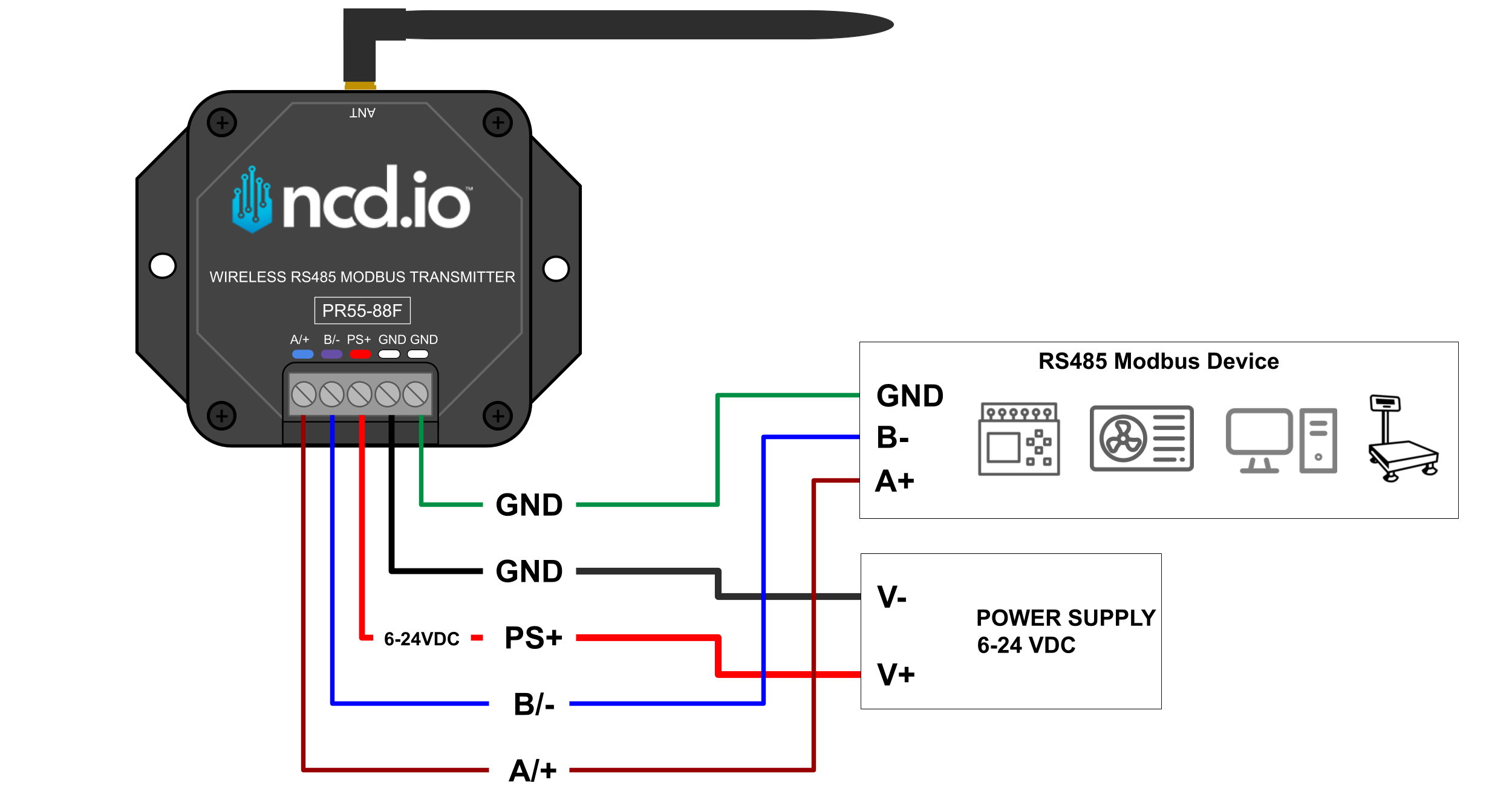
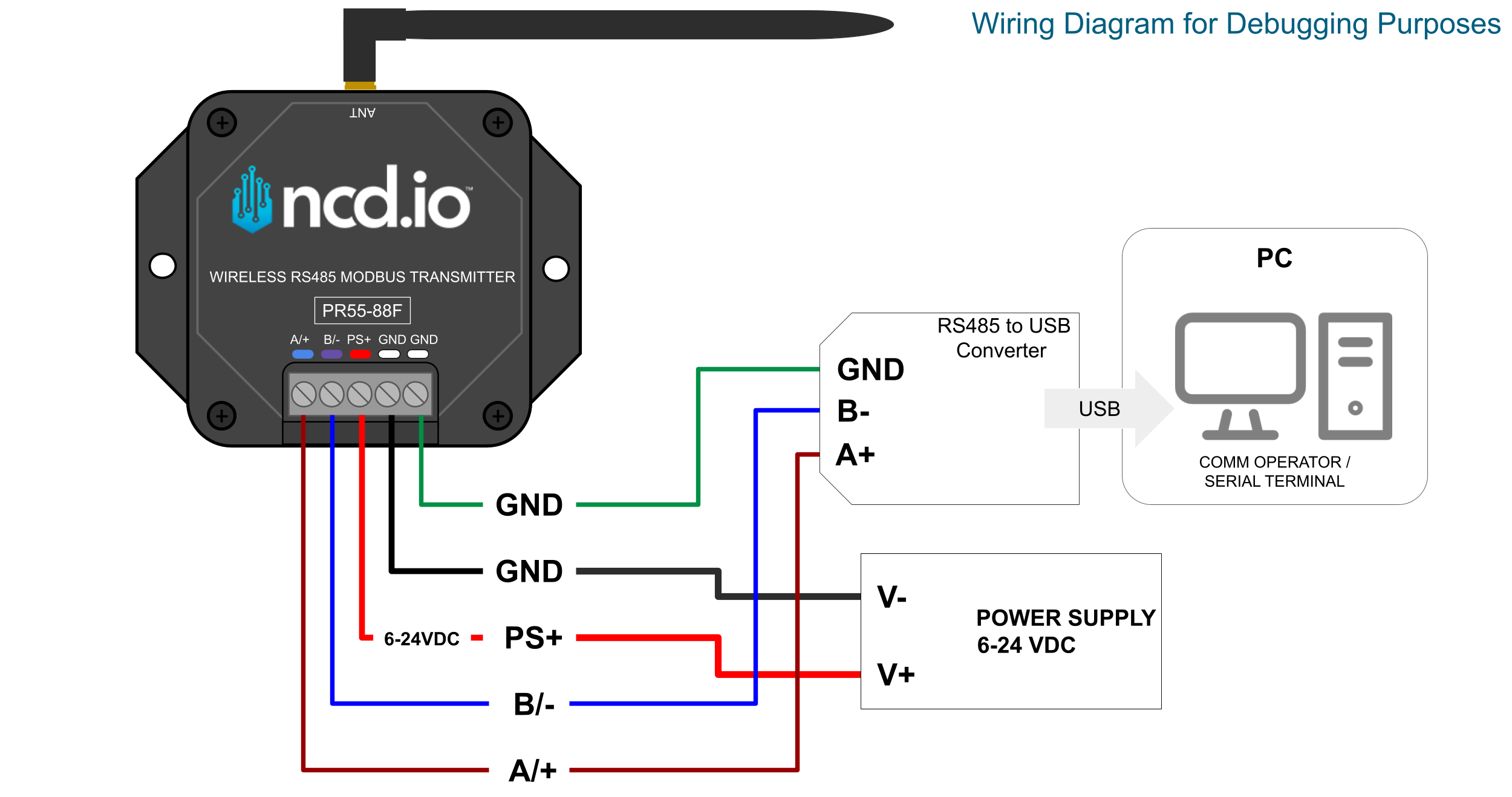
Wiring Connections
RF Module Specifications
| Parameter | 868MHz | 900MHz | 2.4GHz |
|---|---|---|---|
| Frequency Band | 863 MHz to 870 MHz | 902 to 928 MHz | ISM 2.4 GHz |
| Transmitter Power | Up to 13 dBm ERP | Up to 24 dBm | Up to 8 dBm |
| Receiver Sensitivity | -106 dBm at 80 Kbps | -101 dBm at 200 Kbps | -103 dBm at 250 Kbps |
| Range (dense urban) | ~1000ft | ~1000ft | ~300ft |
| Range (line of sight) | ~2 miles | ~2 miles | ~1 mile |
| Data Rate | 80 Kbps | 200 Kbps | 250 Kbps |
| Networking Protocol | Digi XBee® DigiMesh® | Digi XBee® DigiMesh® | Digi XBee® DigiMesh® |
| Encryption | 128-bit AES | 128-bit AES | 128-bit |
| Reliable Packet Delivery | Retries/acknowledgements | Retries/acknowledgements | Retries/acknowledgements |
| IDs | PAN ID and addresses, cluster IDs and endpoints (optional) | PAN ID and addresses, cluster IDs and endpoints (optional) | PAN ID and addresses, cluster IDs and endpoints (optional) |
| Certification | CE/RED, ROHS Compliant | FCC (America), IC (Canada), C-Tick (Australia), Anatel (Brazil), IDA (Singapore) | FCC (America), IC (Canada), RCM (Australia), Anatel (Brazil), Teleck MIC (Japan), KCC (South Korea) |
Power Requirements
This device is has not been designed to run on batteries and can only work with an External power supply (5-32V AC/DC Power Input).