Device Overview
Introducing NCD’s Long Range Industrial IoT wireless vibration and temperature sensor, boasting up to a 2 Mile range using a wireless mesh networking architecture. Incorporating a 16-bit Vibration and Temperature sensor, this sensor transmits highly accurate vibration data at user-defined intervals.
During Power-Up, this vibration sensor learns “normal” base-line vibration from the monitored device. This base-line vibration is subtracted from regular sampled vibration readings to improve relevant vibration data. Ideally, the monitored device should be off while the sensor is learning. Once the sensor stabilizes and starts sending data, the device/machinery being monitored can be powered on.
This Industrial IoT Wireless Vibration Sensor samples 3-axis of Vibration data and then calculates RMS, Maximum, and Minimum vibration readings. This sensor combines these data with temperature data in a data packet, and transmits the result to modems and gateways within wireless range. Once transmission is complete, the vibration sensor goes back to sleep, thus minimizing power consumption.
Features
- Industrial Grade 3-axis Vibration Sensor with ±16g Range
- Calculates RMS, MAX, and MIN g Vibration
- Noise Removal using Low-pass Filter
- Frequency Range (Bandwidth) up to 6400 Hz In Processed Mode
- Frequency Range (Bandwidth) up to 8,000 Hz In Time Domain Mode
- Sample Rate up to 25,600Hz
- Time Domain Data for FFT analysis
- Encrypted Communication with up to 2 Mile Wireless Range
- Operating Temperature Range -40 to +60 °C
- Humidity Range 0-90%
- Wall-Mounted or Magnet Mounted IP65 Rated Enclosure
- For Indoor and Outdoor Use
- Vibration Sensor with External Probe Option
- Up to 100,000 Transmissions from 6 AA Batteries
What is RAW mode data
The vibration sensor works in Processed mode, where it sends data that is obtained from processing its measurements. It effectively samples the acceleration over the x, y, and z axes multiple times per measurement. These are used to generate the processed values that most users are interested. These are the following (where we have a set for each axis):
- rms_ACC_G
- The RMS Acceleration in G
- max_ACC_G
- The MAX Acceleration in G
- velocity_mm_sec
- The Velocity over in mm/sec
- displacement_mm
- The Displacement in mm
- peak_one_Hz
- The frequency at which the First Highest Energy/ Amplitude Peak occurs in Hz
- peak_two_Hz
- The frequency at which the Second Highest Energy/ Amplitude Peak occurs in Hz
- peak_three_Hz
- The frequency at which the Third Highest Energy/ Amplitude Peak occurs in Hz
In addition every message reports the sampling rate in Hz (odr) and the temperature of the probe.
This is probably more than enough data, that is sufficient to identify there is an issue with the machinery. You can also deduce based on the frequency peaks what is the cause, is it misalignment, imbalance, perhaps the bearings have worn down, etc.
For some cases this info is not sufficient, or you simply want to have the raw measurement data to store and process separately. This is what is called RAW mode data. It is literally every measured value over the 3 axis over all the samples, we are talking about thousands of sample points.
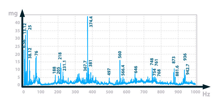
You can use those to perform your detailed analysis, for example via FFT and have the full spectrum of the vibrational signature at the time of the measurement. An example spectrum is presented in the image below.
We have detailed articles on the subject of vibrational analysis you can find at the links:
How to get RAW Mode data
We recommend using Processed + RAW mode if you want to get the raw time domain data. It is not practical to have the sensor transmitting the full set of measurement points all the time as this creates a very large data set (a lot of traffic on the network).
What you can do is observe the processed measurements and if certain thresholds are crossed request RAW data to better evaluate.
We have made it easy for you and incorporated the required API requests into a Node-RED flow. Utilizing it you can easily configure the sensor to response with a RAW data message after it sends is processed data packet. You can copy and import the flow from the code box below:
[{"id":"7a21ba35b8eaf964","type":"ncd-gateway-node","z":"8c51d1a367a55d26","name":"","connection":"","unknown_devices":false,"outputs":1,"x":810,"y":920,"wires":[["fc636a7bda3a9f9b","5ce4d607655f8d89"]]},{"id":"2d3898993f217a4e","type":"inject","z":"8c51d1a367a55d26","name":"","props":[{"p":"payload"},{"p":"topic","vt":"str"}],"repeat":"","crontab":"","once":false,"onceDelay":0.1,"topic":"","payload":"{\"devices\":[\"00:13:a2:00:41:df:2a:76\"]}","payloadType":"json","x":410,"y":780,"wires":[["e79f9a565f911996"]]},{"id":"e79f9a565f911996","type":"function","z":"8c51d1a367a55d26","name":"Add incomming device to context","func":"var newDevices = msg.payload.devices;\nvar existingDevices = flow.get('devices');\n\nif(typeof existingDevices == 'undefined'){\n flow.set('devices',newDevices);\n msg.payload.devices = newDevices;\n return msg;\n}else{\n for(let newDevice of newDevices){\n var exists = false;\n for(let existingDevice of existingDevices){\n if(newDevice == existingDevice){\n exists = true;\n break;\n }\n }\n if(!exists){\n existingDevices.push(newDevice);\n } \n }\n}\nflow.set('devices',existingDevices);\nmsg.payload.devices = existingDevices;\nreturn msg;","outputs":1,"timeout":"","noerr":0,"initialize":"","finalize":"","libs":[],"x":640,"y":780,"wires":[[]]},{"id":"162d7bf7604a5c20","type":"function","z":"8c51d1a367a55d26","name":"Check Devices","func":"var devices = flow.get('devices');\nvar ramdevices = flow.get('ramdevices');\nvar deviceID = msg.payload.addr;\nif(typeof devices == 'undefined')return;\nif(typeof ramdevices == 'undefined'){\n ramdevices = [];\n flow.set('ramdevices',ramdevices);\n}\nfor(var i = 0; i < devices.length; i++){\n // console.log('device: '+devices[i]+' deviceID: '+deviceID);\n if(deviceID == devices[i] && msg.payload.sensor_data.hasOwnProperty(\"x_rms_ACC_G\")){ //for type 80 or 84\n //if (deviceID == devices[i] && msg.payload.sensor_data.hasOwnProperty(\"x1_rms_ACC_G\")) { //for type 81\n if(ramdevices.includes(deviceID)){\n msg.payload.address = deviceID; \n }\n else{\n msg.payload.address = \"00:00:00:00:00:00:ff:ff\" ;\n ramdevices.push(deviceID);\n }\n // msg.payload.address = deviceID;\n // msg.payload.address = \"00:00:00:00:00:00:ff:ff\"\n msg.payload.data = [0xF4,0x4F,0x00,0x00,0x50,0x13]; // type 80 or 84\n // msg.payload.data = [0xF4,0x4F,0x00,0x00,0x50,0x13,0x01]; // type 81 probe one\n // msg.payload.data = [0xF4,0x4F,0x00,0x00,0x50,0x13,0x02]; // type 81 probe two\n // msg.payload.data = [0xF4,0x4F,0x00,0x00,0x50,0x13,0x03]; // type 81 probe one and two\n // msg.payload.data = [0xF7,0x40,0x00,0x00,0x00]; // reboot sensor\n // devices.splice(i,1);\n flow.set(\"ramdevices\",ramdevices);\n return msg;\n \n }\n}","outputs":1,"timeout":"","noerr":0,"initialize":"","finalize":"","libs":[],"x":420,"y":920,"wires":[["6b46842df41c3f3d","f8564028998378b8"]]},{"id":"fc636a7bda3a9f9b","type":"switch","z":"8c51d1a367a55d26","name":"Vibration Check Valve","property":"payload.sensor_type","propertyType":"msg","rules":[{"t":"eq","v":"80","vt":"num"}],"checkall":"true","repair":false,"outputs":1,"x":1020,"y":920,"wires":[["90141c2a23d25330","162d7bf7604a5c20"]]},{"id":"6b46842df41c3f3d","type":"delay","z":"8c51d1a367a55d26","name":"","pauseType":"delay","timeout":"100","timeoutUnits":"milliseconds","rate":"1","nbRateUnits":"1","rateUnits":"second","randomFirst":"1","randomLast":"5","randomUnits":"seconds","drop":false,"outputs":1,"x":610,"y":920,"wires":[["7a21ba35b8eaf964"]]},{"id":"90141c2a23d25330","type":"debug","z":"8c51d1a367a55d26","name":"check vib","active":false,"tosidebar":true,"console":false,"tostatus":false,"complete":"payload","targetType":"msg","statusVal":"","statusType":"auto","x":1220,"y":900,"wires":[]},{"id":"f8564028998378b8","type":"debug","z":"8c51d1a367a55d26","name":"check device","active":false,"tosidebar":true,"console":false,"tostatus":false,"complete":"payload","targetType":"msg","statusVal":"","statusType":"auto","x":610,"y":880,"wires":[]},{"id":"5ce4d607655f8d89","type":"debug","z":"8c51d1a367a55d26","name":"Wireless Gateway out","active":false,"tosidebar":true,"console":false,"tostatus":false,"complete":"payload","targetType":"msg","statusVal":"","statusType":"auto","x":1020,"y":880,"wires":[]}]
You can also find the flow in our Git repo:
https://github.com/ncdcommunity/node-red-request-raw-t80-t81-t84/tree/main
Lets get to configuring/explaining how it works and what you need to edit to make it work with your setup.
Setting up the sensor
If you are in the Processed + RAW mode the sensor sends the standard Processed packet, however it does not immediately go back to sleep, but stays awake for a time period (the Set on Request Timeout in seconds is the parameter that determines how long it does so – see below). If at this point it receives a request to send RAW data, it assembles a RAW data packet and send it.
Requesting the RAW data
Wireless Device node
First of all configure the sensor node with the right address, it should be printed on the casing of your device. Alternately you can get it from the first Processed mode packet.
You also need to enable the “Auto config’ and “OTN Config” settings in order to be able to send configuration info to the sensor.
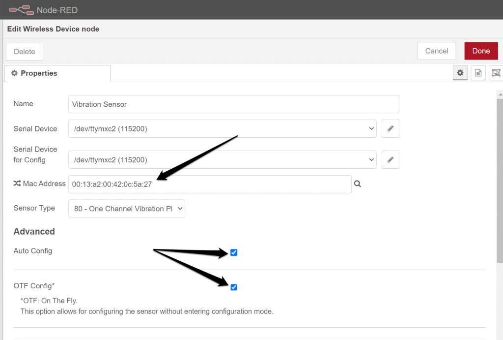
Make sure you change the mode to “Processed + Raw on demand”.

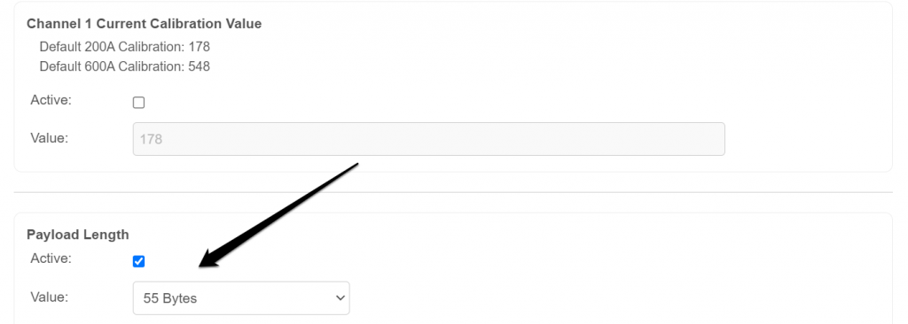
The last step is optional and you only need to execute it if you are using a 2.4GHz device.
Scroll to the very last parameter and set the “Payload Length” to 55Bytes.
Inject node
This node is used to send a downlink command to the sensor requesting the RAW data packet, thus you need to set it up to talk to the right sensor. Open it up and enter the address of the sensor (the same one you used for the Wireless Device node.
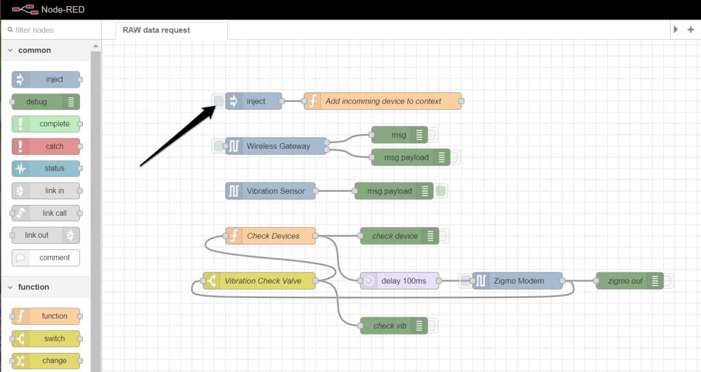
Make sure to only replace the content in the “[]” that is marked in blue in the image below.

Check Devices node
This functional block should be edited in accordance to which sensor you are utilizing. NCD offers a number of Vibration sensors, and depending on which one you are using the code in this block is different. Our example is for the Type 80 (Single Channel Vibration Plus V3).
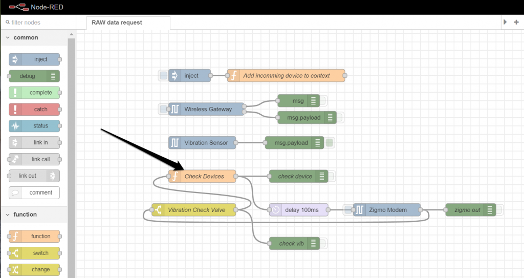
After you open up the node, you need to make sure the lines that refer to the Type 80 are not commented and the rest are (see image below for reference).
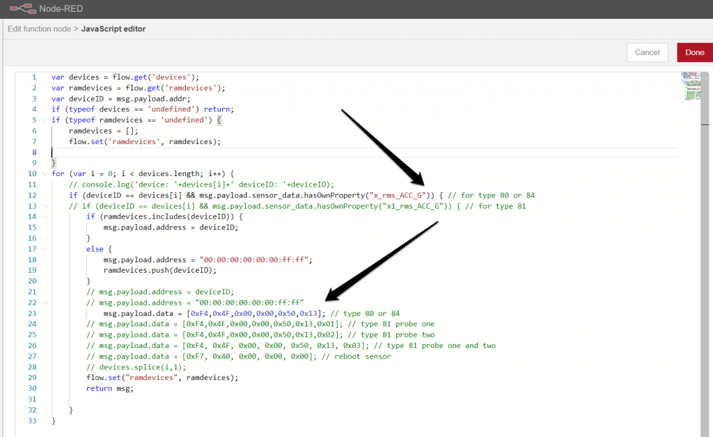
At this point your flow should be configured, you can deploy it and turn on/reset your sensor. If you click the “inject” node at this point it will insert a downlink message to be sent to the sensor after its next uplink message. The sensor will respond to this message with the RAW data packet.
Example RAW mode data
As the RAW data packet request requires the sensor to send a regular data message before hand, essentially you will get two packets:
- Processed data
- RAW data
Let’s look at an example and compare/examine both.
This is your Processed data, as we previously discussed you are given all the metrics the sensor measured in a condensed form over the 3 axes. This is what a regular packet looks like that the sensor reports over time, and its size is significantly smaller than the RAW data packet.
					{
  "mode": 2,
  "odr": "400Hz",
  "temperature": 22.87,
  "x_rms_ACC_G": 0.001,
  "x_max_ACC_G": 0,
  "x_velocity_mm_sec": 0.06,
  "x_displacement_mm": 0,
  "x_peak_one_Hz": 48,
  "x_peak_two_Hz": 51,
  "x_peak_three_Hz": 64,
  "y_rms_ACC_G": 0.001,
  "y_max_ACC_G": 0,
  "y_velocity_mm_sec": 0.08,
  "y_displacement_mm": 0,
  "y_peak_one_Hz": 30,
  "y_peak_two_Hz": 71,
  "y_peak_three_Hz": 7,
  "z_rms_ACC_G": 0.001,
  "z_max_ACC_G": 0,
  "z_velocity_mm_sec": 0.11,
  "z_displacement_mm": 0,
  "z_peak_one_Hz": 69,
  "z_peak_two_Hz": 49,
  "z_peak_three_Hz": 21
}
The RAW data packet that follows the Processed data packet contains only time domain data over the 3 axes. It contains all samples measured by the sensor, in this particular case 800 data points. As you might expect, this is significantly more data than the Processed mode packet and it takes more time and power to be transmitted (which also creates more interference in your network.
Despite these disadvantages, this data is valuable and has its place in Vibration monitoring. For example you could set the sensor up to measured processed data and if the acceleration over one of the axis crosses a certain threshold you request a RAW data packet. This allows you to perform a full Frequency analysis and see the entire spectrum of the Vibrational signal which can give you detailed insights in what the cause of the increased vibration might be.
					{
  "time_id": "0:3",
  "mac_address": "00:13:a2:00:42:0c:5a:27",
  "en_axis": 7,
  "fsr": "4g",
  "odr": 400,
  "device_temp": 22.87,
  "data": {
    "1": {
      "x": 0,
      "y": 0,
      "z": 0
    },
    "2": {
      "x": 0,
      "y": 0,
      "z": 0
    },
    "3": {
      "x": 0,
      "y": 0,
      "z": 0
    ...
    ...
    ...
    "800": {
      "x": 0,
      "y": 0,
      "z": 0
    }
  }
}


