Ethernet Mirror Configuration with NCD5500 Gen 3 Ethernet Module

Introduction

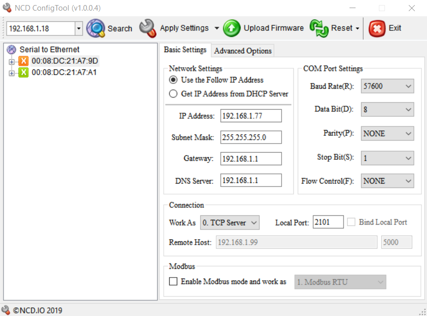
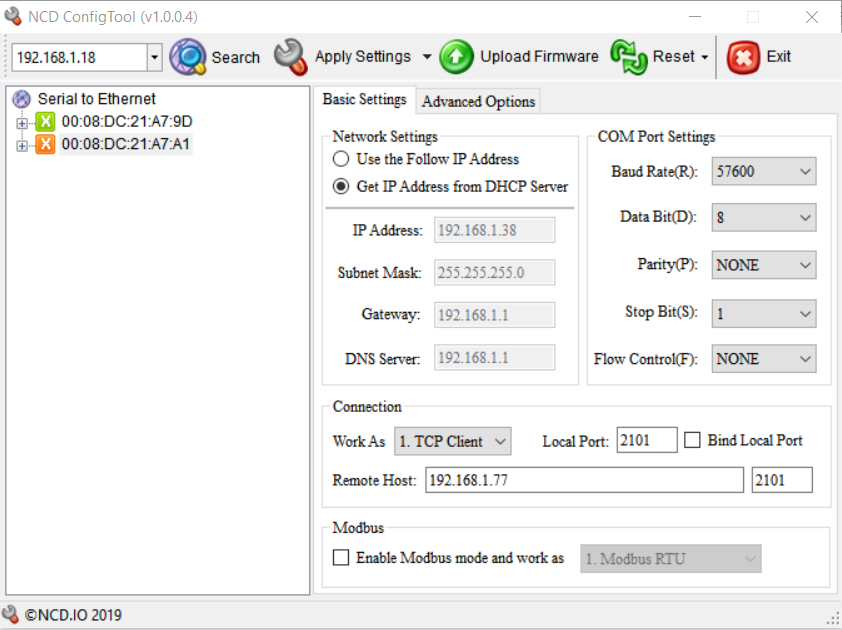
This configuration guide applies to MirC/MirX Ethernet products which utilize the NCD5500 Gen 3 Ethernet module pictured below. In this guide we will cover configuring these Ethernet modules for the MirC/MirX products.  MirC and MirX series products were designed to communicate with each other over a Ethernet network connection.  The contact closure inputs in one location control the relays in the remote location.


Before you Start (Requirements)

It should be noted that these products do not work over an internet connection.  Both boards must be on the same LAN.  Also both boards will require an assigned static IP address.  We recommend that you assign the boards with IP addresses outside the DHCP range of your network router.  If you are connecting these devices to an IT managed network it is recommended that you review this guide with the Network Administrator prior to proceeding.

Each board will utilize a static IP address.  One board will act as the server while the second board will act as the client.  The connection between the two boards is via a TCP socket.  The port number used by this TCP socket is arbitrary and can be configured to any port you wish.  In our setup we used port 2101.  This may be important information if the boards are on separate subnets.  NCD is not capable of providing technical support for complex networks, this should be handled by the Network Admin.

We will be using configuration software which requires Windows so a Windows computer connected to the same network as the boards will be required.  

Initially both boards will be in DHCP mode so a managed network is required, at least for initial configuration.  It is not possible to configure these devices on an unmanaged switch, however after configuration is complete it is absolutely possible to install the boards on an unmanaged network.

Configuration

Initial setup

  1. Download and install the NCD5500 configuration software available here: NCD5500 Configuration Software for Windows
  2. Connect standard Ethernet cables to the boards and plug them into the network.  Then power the boards up using a regulated 12VDC power supply source.
  3. Open the NCD5500 Configuration software.
  4. Click the Search Button in the Configuration software until you have discovered both boards.  You will see them listed by their MAC address.  This Mac address is also printed on top of the Ethernet module installed in the board.  This information can be used to differentiate between the two boards.

First board Configuration (Server)

  1. Click on one of the boards to open it’s settings.  All settings we will be covering will be under Basic Settings.  We do not need to do anything under Advanced Settings.
  2. Set the baud rate to 57600.  
  3. Change the Network Settings Radio button to Use the Follow IP address.  
  4. Enter a Static IP address for the board into the IP address field, and enter information into Subnet Mask, Gateway, and DNS Server as per the requirements of your network.
  5. If you would like this board to act as the Server(does not matter which board you choose to act as the server) then Under Connection set Work As to TCP Server.  Set the Local Port field to any port you wish other than 80.  This will be the port the module listens for incoming TCP Socket connections on.  This information is applicable if there are any firewalls.  For our setup we are using port 2101.
  6. Click Apply Settings.

You can review a screen shot of our Server configuration below:

Second Board Configuration (Client)

  1. Click on the other board in the list to open it’s settings.  
  2. Set the baud rate to 57600.  
  3. Change the Network Settings Radio button to Use the Follow IP address.
  4. Enter a Static IP address for the board into the IP address field, and enter information into Subnet Mask, Gateway, and DNS Server as per the requirements of your network.
  5. This board will act as the Client and will connect to the previous board we configured.  Click the Work As Drop down menu and change it to TCP Client.  Do not worry about the Local Port Setting as it does not apply.
  6. Enter the Static IP address entered for the first board acting as the server into the Remote Host field.
  7. Enter the Port number entered as the Local Port on the first board acting as the Server into the Port field to the right of the Remote Host Field.
  8. Click Apply Settings.

You can review a screen shot of our Client configuration below:

Final Testing

Both boards should now be configured and should work.  You can validate that the boards have a valid TCP socket connected by checking the Red LED on the Ethernet module adjacent to the metal Ethernet Jack.  If it is on solid then the connection is established between the boards.  You may also monitor the Busy/Ready LEDs on the boards which should flash on/off periodically indicating the boards are communicating.  You may now close the inputs on the boards and should see the relays on the remote unit turning on/off.