Introduction
In this article, we will walk through the step-by-step process of controlling the digital outputs and reading the digital inputs of the Enterprise IIoT Gateway using Node-RED. While the Enterprise IIoT Gateway runs a Linux-based operating system, some initial configurations are required before accessing the peripherals from Node-RED. This tutorial will guide you through the necessary setup to accomplish this.
This article is based on the work of Chase Grant.
Overview
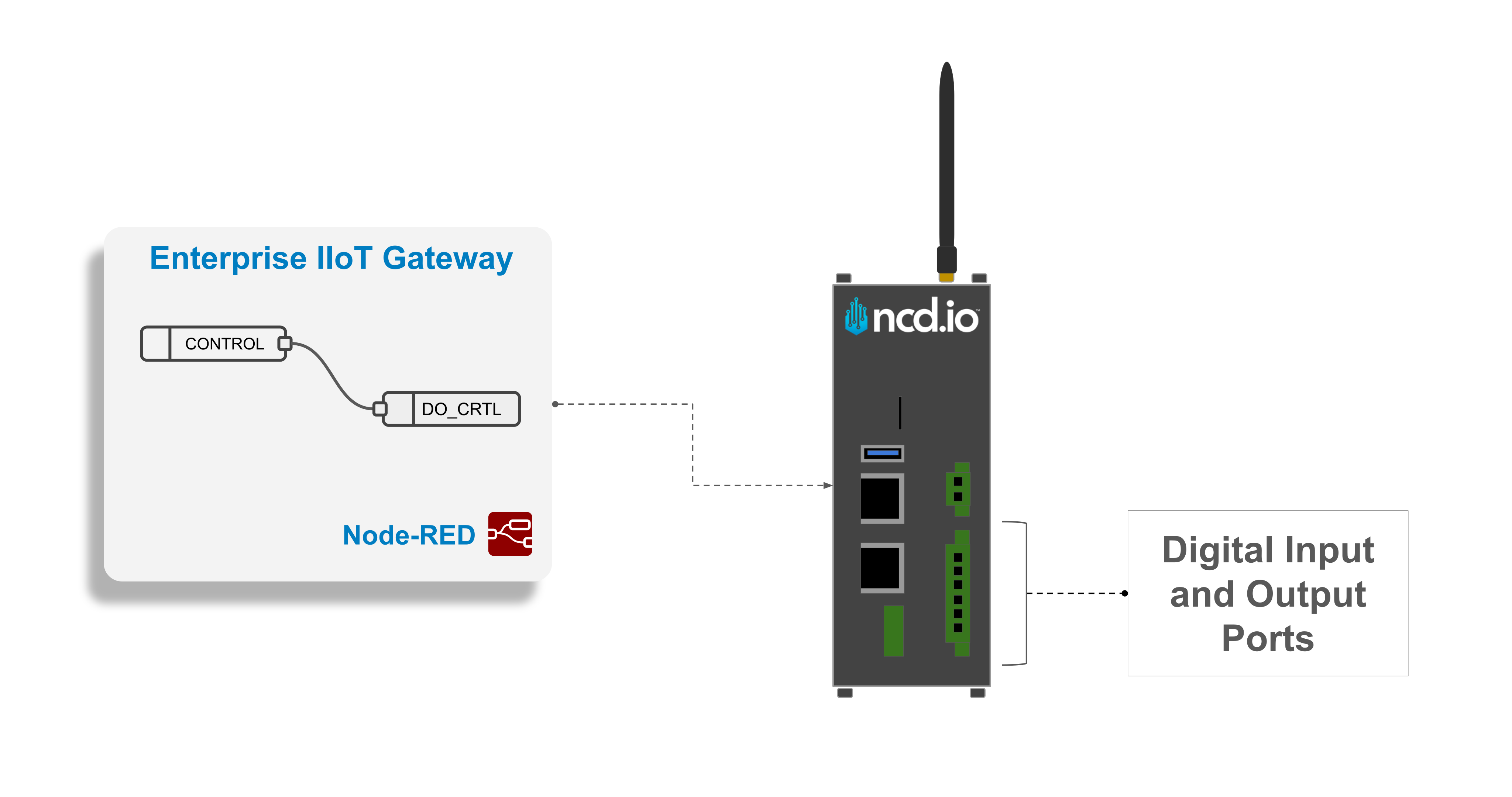
Using Node-RED, we created a flow example to control the digital outputs and read the digital inputs of the Enterprise IIoT Gateway. This flow will serve as a foundation, allowing you to later integrate logic to automate the process—for example, enabling or disabling a digital output based on the value of an NCD sensor variable or reading the status of a digital input and using it to control a digital output.

Requirements
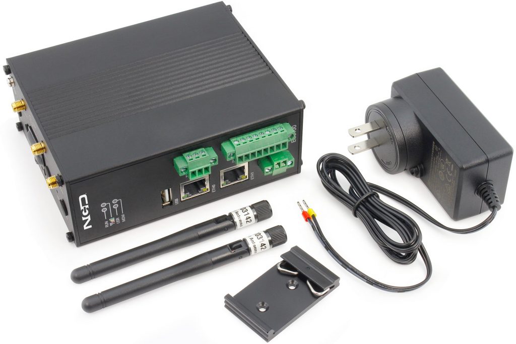
Enterprise IIoT Gateway
In order to follow along with this guide you will need these components:
The Enterprise IIoT Gateway is designed to simplify, streamline, and customize your NCD IIoT installation. It features built-in Node-RED capabilities for no-code integration into new or existing cloud/SCADA systems, web-based security and access management, SSH access to the Debian OS for full customization, as well as VPN and remote management options. This edge computer ensures a seamless deployment experience.
We offer two versions of the Enterprise IIoT Gateway: a standard version with all features, including integrated Wi-Fi, Ethernet, and cellular connectivity, and a Lite version with reduced CPU and RAM capabilities, and no cellular connectivity.
Node-RED
Node-RED is a visual programming tool that provides a browser-based editor for creating applications by connecting predefined functions (nodes). Despite its technical nature, Node-RED offers a user-friendly interface. As an open-source project under the OpenJS Foundation, it is free to use with no subscription fees. You can install and run Node-RED locally on your PC, or, in the case of our Enterprise IIoT Gateway, it comes pre-installed and operates as a service. Node-RED, in conjunction with our Enterprise NCD library, forms a powerful tool for acquiring, managing, configuring, and uploading firmware through an intuitive interface. This combination offers a streamlined approach to optimizing the setup, configuration, and management of NCD sensor data.
Here you can find a complete getting started guide for accessing Node-RED from the Enterprise IIoT Gateway:
Interface Overview
The Enterprise IIoT Gateway, available in Standard and Lite versions, offers a versatile set of interfaces for industrial IoT applications. This section provides a detailed overview of the gateway’s available ports and pins, including Micro SD, USB, Ethernet, power input, RS232/485, and digital input/output channels. We’ll also explore the differences between the Standard and Lite versions and present an example internal/external diagram illustrating the use of a digital signal to control an output.
The image on the right details the DI/DO interface of the Enterprise IIoT Gateway, highlighting the number of available ports, types of connections, and supported electrical ranges for the digital input and output interface.
Additionally, it includes a basic example diagram for a digital output (e.g., controlling a relay) and a digital input (e.g., reading a PNP sensor state), which you can use as a reference for proper setup.
Procedure
Before you can manipulate the digital inputs and outputs on the Enterprise IIoT Gateway, you need to properly configure the device to ensure seamless operation. This section provides a step-by-step guide to prepare the gateway, divided into two key subsections. First, in the Rules Configuration subsection, you’ll learn how to SSH into the Enterprise IIoT Gateway, navigate to the specified directory, download the .rules file from GitHub, add a user, and reboot the gateway to apply the changes. Next, in the Node-RED Flow Configuration subsection, we’ll guide you through downloading a Node-RED flow from GitHub, importing it into your Node-RED project, and understanding each component of the flow through a detailed explanation. By following these steps, you’ll have the gateway fully prepared to control and monitor its digital I/O interfaces effectively.
Interface Configuration
The first step is to enable the digital inputs on the Enterprise IIoT Gateway through its web configuration dashboard. To access the web configuration dashboard, follow this guide, go to Access the Web Configuration Interface section:
Step 4. repeat steps 2 & 3 for each DI or DO they want to utilize
Step 5. After enabling the digital input, the settings window will close. Then, click the Submit button.

Step 6. Finally, click the Save and Apply button in the top right corner of the interface page. This action will save and apply all configuration changes made on the Enterprise IIoT Gateway, ensuring the digital inputs are fully enabled. After this step, you can safely log out from the UI dashboard interface.

Rules Configuration
Step 1. SSH into your Enterprise IIoT Gateway: We have an article that explains how to SSH into the Enterprise IIoT Gateway — you can review it before continuing. Once you’ve successfully connected via SSH, you can come back here to follow the next steps.
Step 2. This command changes the working directory:
cd /etc/udev/rules.d
Step 3. The command downloads the .rules file from GitHub into the /etc/udev/rules.d directory. Here, sudo grants elevated permissions, curl fetches the file, and -O saves it with its original name.
The 98-led-permissions.rules file contains udev rules that configure permissions for the Enterprise IIoT Gateway’s digital output ports, specifically do1 and do2, which are often used to control devices like relays. Each line in the file tells the system how to manage these outputs when they are detected.
					 SUBSYSTEM=="leds", KERNEL=="do2", RUN+="/bin/chmod 666 /sys/class/leds/do2/trigger"
 SUBSYSTEM=="leds", KERNEL=="do2", RUN+="/bin/chmod 666 /sys/class/leds/do2/brightness"

 SUBSYSTEM=="leds", KERNEL=="do1", RUN+="/bin/chmod 666 /sys/class/leds/do1/trigger"
 SUBSYSTEM=="leds", KERNEL=="do1", RUN+="/bin/chmod 666 /sys/class/leds/do1/brightness"
Step 5. Finally, execute the follow command to restart the Enterprise IIoT Gateway.
sudo reboot
Node-RED Flow
Now that the Enterprise IIoT Gateway is configured, it’s time to implement a Node-RED flow to manage its digital inputs and outputs. This section will walk you through downloading a ready-made Node-RED flow from GitHub and importing it into your Node-RED workspace, enabling you to interact with the gateway’s digital I/O ports.
Importing Flow
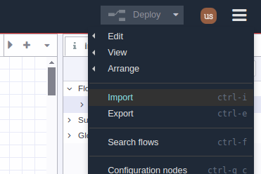
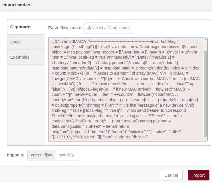
Step 1. The first step is to go to the github repository where the flow is located and click on the ‘Copy Raw’ button as shown in the image, this allows you to copy the flow and then import it into Node-RED.
Checking DI Flow
In the Checking DI Node-RED flow, an Exec node is configured with the command cat /dev/input/event2 to read data from a digital input on the Enterprise IIoT Gateway. Here, cat is a Linux command that outputs the contents of a file, and /dev/input/event2 is a special file in the Linux system representing an input device, such as a digital input port (e.g., a switch or sensor connected to the gateway).
When a digital input changes state (e.g., a switch is pressed), this file captures the event, and the cat command streams the raw event data. The Exec node in Node-RED executes this command and passes the output to the flow, allowing you to monitor the digital input’s state in real time and trigger actions based on the input events.
Digital Output Flow
In the Digital Output Node-RED flow, two sets of commands are used in an Exec node to control the do1 digital output on the Enterprise IIoT Gateway, such as turning on or off a connected device like an LED or relay:
echo none > /sys/class/leds/do1/trigger; echo 1 > /sys/class/leds/do1/brightness
- Turning do1 On: The first command, echo none > /sys/class/leds/do1/trigger, sets the trigger file to “none,” disabling any automatic behavior (e.g., blinking) and allowing manual control of the output. The second command, echo 1 > /sys/class/leds/do1/brightness, writes 1 to the brightness file, turning the do1 output on (e.g., activating the connected LED or relay).
echo none > /sys/class/leds/do1/trigger; echo 0 > /sys/class/leds/do1/brightness
- Turning do1 Off: Similarly, echo none > /sys/class/leds/do1/trigger ensures manual control by setting the trigger to “none.” Then, echo 0 > /sys/class/leds/do1/brightness writes 0 to the brightness file, turning the do1 output off (e.g., deactivating the connected LED or relay).
Summary
This guide demonstrated how to control and monitor the digital inputs and outputs of the Enterprise IIoT Gateway (Standard and Lite versions) using Node-RED. We explored the gateway’s pinout, detailing its ports and pins, and provided an example of controlling a digital output, such as toggling a relay or LED, based on a digital signal. This setup serves as a foundation for creating advanced automations by integrating sensor data or digital inputs, enabling you to enhance your industrial IoT applications with scalable logic and real-time control.
Thank you, NCD Team
Share this on


