Device Overview
Linear displacement sensors are typically used for structural monitoring applications, allowing movement and shift detection between two points. Install this linear displacement sensor between footings and walls, or between walls and steel support structures. Any movement (due to temperature, earthquakes, or structural failure) will be reported by this sensor. Use this linear displacement sensor for measurement of distances between two points, such as positional control systems, lifting and spreader beam testing, hydraulic movement detection, and structural crack monitoring. With pivot bearings included at each end, this sensor is capable of monitoring shifts in position that may not always be perfectly linear without damage to the sensor. With a IP65 rating, this device is ideally suited for indoor or outdoor use.
This long range IoT wireless Linear Displacement Sensor incorporates a 1 channel 10-bit ADC that samples Linear Displacement at user defined intervals and sends a wireless transmission to remote gateways and modems. After sampling, this device goes to sleep to minimize power consumption and prolong battery life. This IoT Wireless Linear Displacement Sensor has an additional feature of detecting change in position every 7 seconds (user configurable) and sending out Displacement value if the change in Displacement is greater than 10% (user configurable). To minimize power consumption, it sleeps during the time it is not checking for change in Displacement level. Both of these features work together, supporting multiple application areas in one package. This Wireless IoT Linear Displacement Sensor outputs a analog value. The value range is between 0 and 1023. An output value 1023 indicates that the displacement probe is fully extended while a value of 0 indicates the sensor is fully contracted.
- Wireless Linear Displacement Sensor for Structural Monitoring
- Industrial Grade IoT Displacement Sensor with Max Speed 5m/Sec
- 10-bit Resolution & Linear Precision 2% FS
- Auto ADC Sample Transmission on Level Change
- Configurable 10% Analog Voltage Change Detection
- 2 Mile Line-of-Sight Range with On-Board Antenna
- NCD provides a compete set of Node-RED libraries
- Wireless Mesh Networking using DigiMesh®
- Open Communication Protocol for Easy Software Integration
- Includes Battery Level with Every Transmission
- Validates and Retries Lost Communication Packets
Status LED
The Status LED is used to indicate errors or other sensor diagnostics.
LED blinks once – Message was sent successfully and no error in last sensor read as well in data transmission.
LED blinks twice and then one more time – Message was sent successfully but there was an error in last sensor read.
LED blinks thrice – MCU is having issue communicating with the radio module.
Sensor Specifications
| Specifications | Minimum | Nominal | Maximum | Notes |
|---|---|---|---|---|
| Width | 3.54" | |||
| Length | 4.52" | |||
| Height | 2.16" | |||
| Enclosure Rating | IP65, NEMA 1,2,4,4X,12,13, UL-508 | |||
| Mounting | 1/4 NPT 1/4-28 UNF Magnet Mount | |||
| Temperature Rating | -40° C | 23° C | 85° C | Component Rating |
| Tested Temperature | 0° C | 23° C | 40° C | As Tested by NCD Staff |
Printed Circuit Board Specifications
| Parameter | Minimum | Nominal | Maximum | Notes |
|---|---|---|---|---|
| Trace Width | 0.007 inch | 0.012 inch | 0.25 inch | Trace Width depends on the Trace Type |
| Layer Count | 2L - Rigid | Top and Bottom Layer | ||
| Material Type | FR-4 TG170 | FR-4 TG170 | FR-4 TG180 | |
| Surface Finish | ENIG 2u" | |||
| IPC Standard | IPC CLASS 2 | |||
| Finished Copper Foil | 1.0/1.0 OZ | |||
| Finished Thickness | 0.062 inc | |||
| Fine line <4.0/4.0mil | No | |||
| Blind & Burried Vias | No | |||
| Non-Conductive Resin | No | |||
| Conductive Resin | No |
Mechanical Drawing

RF Module Specifications
| Parameter | 868MHz | 900MHz | 2.4GHz |
|---|---|---|---|
| Frequency Band | 863 MHz to 870 MHz | 902 to 928 MHz | ISM 2.4 GHz |
| Transmitter Power | Up to 13 dBm ERP | Up to 24 dBm | Up to 8 dBm |
| Receiver Sensitivity | -106 dBm at 80 Kbps | -101 dBm at 200 Kbps | -103 dBm at 250 Kbps |
| Range (dense urban) | ~1000ft | ~1000ft | ~300ft |
| Range (line of sight) | ~2 miles | ~2 miles | ~1 mile |
| Data Rate | 80 Kbps | 200 Kbps | 250 Kbps |
| Networking Protocol | Digi XBee® DigiMesh® | Digi XBee® DigiMesh® | Digi XBee® DigiMesh® |
| Encryption | 128-bit AES | 128-bit AES | 128-bit |
| Reliable Packet Delivery | Retries/acknowledgements | Retries/acknowledgements | Retries/acknowledgements |
| IDs | PAN ID and addresses, cluster IDs and endpoints (optional) | PAN ID and addresses, cluster IDs and endpoints (optional) | PAN ID and addresses, cluster IDs and endpoints (optional) |
| Certification | CE/RED, ROHS Compliant | FCC (America), IC (Canada), C-Tick (Australia), Anatel (Brazil), IDA (Singapore) | FCC (America), IC (Canada), RCM (Australia), Anatel (Brazil), Teleck MIC (Japan), KCC (South Korea) |
Power Requirements and Expected Battery Life
Power Requirements
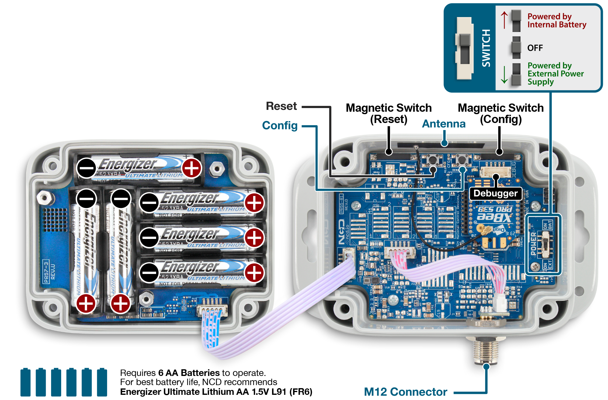
This Sensor has two power options:
- Powered by AA batteries (NCD recommends Energizer L91 batteries)
- External power supply (5-12 V DC) Current Requirement 250 mA (optional)
While changing the batteries:
- Turn off the sensor
- Only use new L91 batteries
- Checkout the polarity marking on the battery holder and batteries
- Replace all six batteries with new L91 batteries. Do not mix old and new batteries
- Batteries should not be replaced in fire-risky areas
- Do NOT install rechargeable batteries
Expected Battery Life
| Specifications | Minimum | Nominal | Maximum | Notes |
|---|---|---|---|---|
| Batteries | 2 | 6 | 6 | May be Powered by 2 or 6 AA Batteries |
| Battery Life 1 TPD (TPD Transmissions per Day) | 10 Years | Battery estimation is based on a 30 min interval | ||
| Battery Life 12 TPD (TPD Transmissions per Day) | 8 Years | Battery estimation is based on a 30 min interval | ||
| Battery Life 24 TPD (TPD Transmissions per Day) | 5 Year | Battery estimation is based on a 30 min interval | ||
| Battery Life 96 TPD (TPD Transmissions per Day) | 3 Year | Battery estimation is based on a 30 min interval |
Head to the NCD store if you want to purchase the C1D2 Industrial IoT Wireless Linear Displacement Sensor.
If you already have the device and would like more information into its basic and advanced operations check out the Quick Start Guide and User Manual.