Device Overview
The Industrial IoT Ultrasound Vibration Sensor from NCD – a high-performance solution engineered explicitly for industry-leading predictive maintenance applications. Integrated with a wireless mesh networking architecture, it delivers an impressive range of up to 2 miles. The sensor employs a high-precision, dual-channel 15-bit ADC, capturing vibration data at user-specified intervals and wirelessly transmitting the recorded data to remote modems and gateways.
Designed with a focus on energy efficiency, the sensor seamlessly transitions into an ultra-low power sleep mode between data sampling periods. Its integrated 16V buck-boost power supply negates the requirement for an external power source, enhancing its versatility.
Powering the sensor are six AA batteries that, coupled with an operational capacity of up to 100,000 wireless transmissions, afford an estimated battery lifespan of 10 years. This lifespan depends on environmental conditions and the frequency of data transmissions. The sensor also supports optional external power from a 6-18VDC supply for added flexibility.
Its superior range, high precision, extended battery life, cost-effectiveness, and fortified security features position this sensor as an exceptional tool for predictive maintenance tasks in various industrial contexts, exceeding the standards set by traditional devices.
- Industrial Grade 1-Channel Ultrasound Vibration Sensor
- Resonant frequency Fres = 37 [kHz] +/- 1 [kHz]
- Measuring range 20 to 100 [dBµVRMS]
- Resolution 0.5 [dB𝜇𝑉RMS]
- Ideal For Motors, Pumps, and Gear Box Predictive Maintenance
- 2 Mile Line-of-Sight Range with On-Board Antenna
- Superior LOS Range of up to 28 Miles with High-Gain Antennas
- Wireless Mesh Networking using DigiMesh®
- Open Communication Protocol for Easy Software Integration
- Validates and Retries Lost Communication Packets
Frame Structure
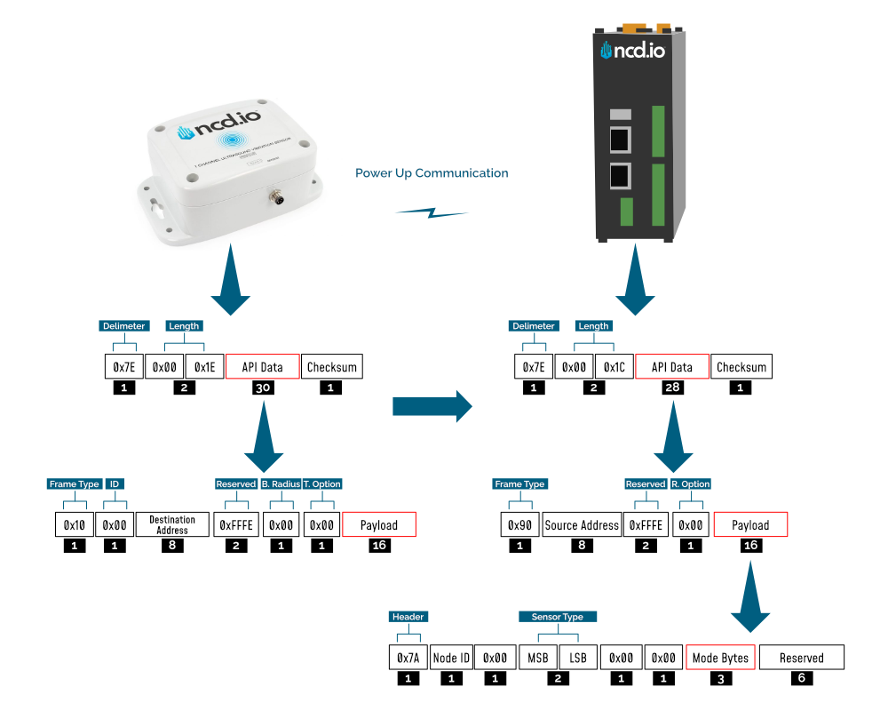
Frame Communication at Power Up
When the device powers up, depending on the mode it is going to work in, it will have a different Power Up Frame
Figure 3 provides an outline of the frame structure at Power Up, where the bytes highlighted in Red denote which mode the device has started in (Run, Configuration or Factory Default). You can look up the corresponding codes in Table 2.
If we further examine the Payload, we can use the Node ID and Sensor Type fields to determine the exact sensor that is sending the data.
A shown in the second column in Table 2, the sensor configures its PAN ID automatically depending upon the mode it is working in. During factory reset it sets the PAN ID to the value given in table therefore the factory reset frame will only be received if your Modem/Gateway PAN ID matches this ID. All 3 types of frames are shown in Figure 3, Figure 4 and Figure 5.
| Mode Type | PAN ID set by Sensor (ASCII) | Frame field | Offset (Payload section) | Value |
|---|---|---|---|---|
| Run | ID save by user / Default | Mode bytes | 7 | 0x52 |
| 8 | 0x55 | |||
| 9 | 0x4E | |||
| Configuration | 7BCD | Mode bytes | 7 | 0x50 |
| 8 | 0x47 | |||
| 9 | 0x4D | |||
| Factory Reset | 7FFF | Mode bytes | 7 | 0x50 |
| 8 | 0x55 | |||
| 9 | 0x4D |
Let us look at the 3 possible power up frames to give an example:
Run Mode Power Up Frame
| Field | Number of bytes | Description |
|---|---|---|
| 7E 00 1C 90 00 13 A1 00 41 58 1C CB FF FE 00 7A 01 00 00 01 00 00 52 55 4E 00 00 00 00 00 00 0B | Example frame | |
| 0x7E | 1 | Delimiter |
| 0x001C | 2 | Length |
| 0x90 | 1 | Frame Type (Power Up) |
| 0x0013A1004158C1CB | 8 | Source Address |
| 0xFFFE | 2 | Reserved |
| 0x00 | 1 | R. Option |
| 0x7A | 1 | Header with Power Up value |
| 0x01 | 1 | Node ID |
| 0x00 | 1 | Separator |
| 0x0001 | 2 | Sensor Type |
| 0x0000 | 2 | Separator |
| 0x52554E | 3 | Mode Byte for Run Mode |
| 0x000000000000 | 6 | Reserved |
| 0x0B | 1 | Checksum |
Configuration Mode Power Up Frames
| Field | Number of bytes | Description |
|---|---|---|
| 7E 00 1C 90 00 13 A1 00 41 58 1C CB FF FE 00 7A 01 00 00 01 00 00 50 47 4D 00 00 00 00 00 00 1C | Example frame | |
| 0x7E | 1 | Delimiter |
| 0x001C | 2 | Length |
| 0x90 | 1 | Frame Type (Power Up) |
| 0x0013A1004158C1CB | 8 | Source Address |
| 0xFFFE | 2 | Reserved |
| 0x00 | 1 | R. Option |
| 0x7A | 1 | Header with Power Up value |
| 0x01 | 1 | Node ID |
| 0x00 | 1 | Separator |
| 0x0001 | 2 | Sensor Type |
| 0x0000 | 2 | Separator |
| 0x50474D | 3 | Mode Byte for Configuration Mode |
| 0x000000000000 | 6 | Reserved |
| 0x0E | 1 | Checksum |
Factory Reset Mode Power Up Frames
| Field | Number of bytes | Description |
|---|---|---|
| 7E 00 1C 90 00 13 A1 00 41 58 1C CB FF FE 00 7A 01 00 00 01 00 00 50 47 4D 00 00 00 00 00 00 1C | Example frame | |
| 0x7E | 1 | Delimiter |
| 0x001C | 2 | Length |
| 0x90 | 1 | Frame Type (Power Up) |
| 0x0013A1004158C1CB | 8 | Source Address |
| 0xFFFE | 2 | Reserved |
| 0x00 | 1 | R. Option |
| 0x7A | 1 | Header with Power Up value |
| 0x01 | 1 | Node ID |
| 0x00 | 1 | Separator |
| 0x0001 | 2 | Sensor Type |
| 0x0000 | 2 | Separator |
| 0x50474D | 3 | Mode Byte for Configuration Mode |
| 0x000000000000 | 6 | Reserved |
| 0x0E | 1 | Checksum |
Sensor Data Frame
Run mode is the default mode of operation of this sensor. In this mode, the device sends periodic packets with the sensor measurement data. During the time it is not sending it enters deep-sleep to conserve power. The sensor’s X-bee module operates in API mode and sends packets to the saved destination address on the network specified by the saved PAN ID. Figure 4 illustrates the API transmission/reception procedure.
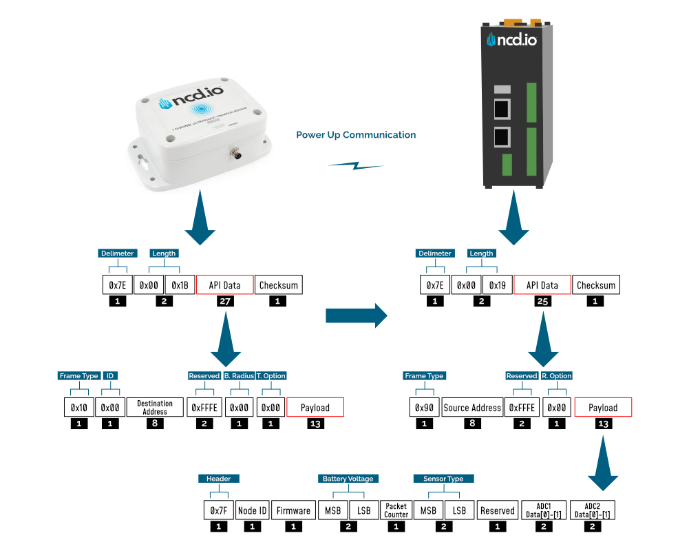
The detail of Payload section of packet is shown in table below:
| Frame Field | Offset (Payload section) | Fixed Value (if any) | Description |
|---|---|---|---|
| Header | 0 | 0x7F | Header to differentiate various types of packets |
| Node ID | 1 | 0x00 (Factory Default) | Node ID to differentiate up to 256 nodes in a network. User configurable values |
| Firmware | 2 | - | Used to determine firmware version programmed in the device |
| Battery Voltage | MSB 3 | - | Battery Voltage = ((Battery Voltage MSV x 256) + Battery Voltage LSB) x 0.00322 V |
| LSB 4 | - | ||
| Packet Counter | 5 | - | It is an 8-bit counter that increments with each packet transmission. It can be used to detect missing packets |
| Sensor Type | MSB 6 | 0x00 | Two bytes to determine sensor type. It can be used in conjunction with Node ID to create sensor networks of up to 256 nodes for a single type of sensor and multiple such networks can coexist and can be differentiated in processing software on PC end. |
| LSB 7 | 0x58 | Sensor type 88 | |
| Error/Reserved byte | 8 | 0x00 | For future use |
| Sensor Data | 9 / Data[0] | - | ADC 1 Counts |
| 10 / Data[1] | - | Counts = (Data[0] x 256) + Data[1] | |
| 11 / Data[2] | - | mA Value | |
| 12 / Data[3] | - | mA Value = ((Data[2] x 256) + Data[3])/100 | |
| 13 / Data[4] | - | Vibration dB Value | |
| 14 / Data[5] | - | dB Value = ((Data[4] x 256) + Data[5])/100 |
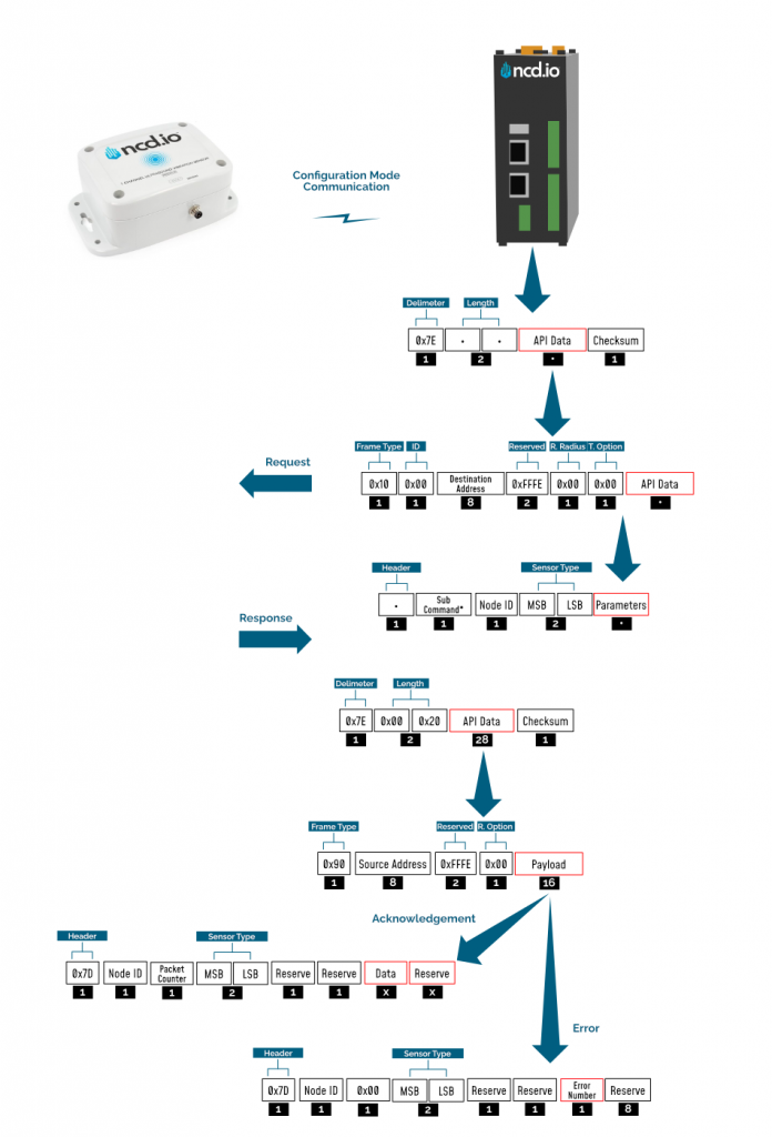
Configuration Mode Frame
Configuration Mode (enter via CFG key press for 7 seconds at power up) is intended to setup the device over the wireless link, you can change parameter values that are subject to change via downlink commands.
When in Configuration Mode a FLY message is sent that if responded to with an OTN message extends the configuration window to 60 seconds so you can push multiple configuration changes.
In configuration mode, the device sets its X-bee pan id to 7BCD. Also, the destination address used by the sensor is extracted from the incoming packet (source address). This ensures that once you put a device in configuration mode you just need to change the PAN ID you are sending to in your Modem/Gateway to match with the sensor and start configuring your device.
A standard configuration packet and its fields are explained in Figure 5. Its possible responses are also shown. The complete set of commands supported by this sensor are shown in тхе Appendix, these can be used in the Parameters field of the Payload section. The sensor responds to these commands with an acknowledgement if the process completed successfully or with an error if it failed to setup a parameter. The respective Data and Reserve section length and values are shown in Table 6 for the case of acknowledgement. In the case of error, the reserved section will be fixed and not used, while the Error number byte will determine the type of error returned. These errors are in a separate section in the Appendix.
Example Configuration Commands
The following set of commands are an example on how to change some of the parameters that affect the operation of sensor (these are parameters that are general in nature, more on a network protocol/device level than device specific). The relate to settings that are independent of the type of probe used. You can find them in Appendix together wit the Device/Application Specific commands.
Set Sensor Node ID and Sleep Duration
This Command may be used to set the sensor node and sleep duration, note that both values are stored together using the same command. The Node ID is a user-defined value from 00 to FF that may be used to help easily identify a sensor. The Sleep Duration indicates the amount of time (in seconds) the sensor will sleep before waking up, taking a sample, sending a transmission, and going back to sleep.
Set Node ID and Sleep Duration Command Example:
7E 00 17 10 01 00 00 00 00 00 00 FF FF FF FE 00 00 F7 02 00 00 00 01 00 00 0A
In the above command, the remote device address is set to broadcast mode. The broadcast address is 00 00 00 00 00 00 FF FF, which will target all sensors in configuration mode. Change the broadcast address to the MAC address of a individual sensor to target a particular sensor with this command (this is usually not required). The Command Contains a Sensor payload which contains a Sensor Node ID and Delay value.
Payload
F7 02 00 00 00 01 00 00 0A
Note that F7 is the command header byte and 02 is the sub command for storing the Node ID and Sleep Duration.
A. Node ID
0x01 (Byte 23)
B. New Delay Value
00 00 0A (data bytes 24, 25, and 26)
Delay in seconds = (0x00 x 65536) + (0x00 x 256) + 0x0A = 10 Seconds = 10 Seconds
In the Above command we set the new node to 1 and sleep duration value to 300 seconds (5 Minutes).
Once the sensor receives this command, it will send a response back. This response will indicate success or failure of the command.
In his case, the response will look something like this:
7E 00 1C 90 00 13 A2 00 41 91 1B 83 FF FE C1 7C 01 05 00 0E 00 00 FF 00 00 00 00 00 00 00 00 FD
Read Sleep Duration
This command may be used to read the sensor sleep duration. The sleep duration determines how frequently the sensor wakes up and send sensor data. The interval is set in seconds. Short intervals will drain the battery faster while longer intervals will provide a very long battery life.
Read Sleep Duration Command
7E 00 13 10 00 00 00 00 00 00 00 FF FF FF FE 00 00 F7 15 00 00 00 E8
In the above command the remote device address is set as broadcast. The address is:
00 00 00 00 00 00 FF FF
When sending this command to a particular sensor, replace the MAC address of the sensor. Again, the sensor MUST be in configuration mode.
The Wireless Sensor will respond with the stored delay value:
7E 00 1C 90 00 13 A2 00 41 91 1B 83 FF FE C1 7C 00 02 00 0E 00 00 00 02 58 00 00 00 00 00 00 A6
From the above command, the following data may be extracted:
A. Sensor MAC address
00 13 A2 00 41 91 1B 83
B. Sensor Over-all Payload
7C 00 02 00 0E 00 00 00 02 58 00 00 00 00 00 00
C. Delay Value
0x00 0x02 0x58 (data bytes 23, 24, and 25)
Delay in Seconds = (0x00 x 65536) + (0x02 x 256) + 0x58 = 600 Seconds = 10 Minutes
This Command may be used to set the sensor destination address to broadcast mode, which is the default operation of NCD long range wireless sensors. After setting to broadcast mode, all modems and gateways with the same PAN ID and Encryption key will receive the same sensor data. This is the preferred configuration for all NCD sensors. Segmenting sensors into groups requires a unique PAN ID (also known as Network ID) for each group. All sensors, modems, and gateways must share the same PAN ID for each group.
Set Sensor Destination address to broadcast:
7E 00 13 10 00 00 00 00 00 00 00 FF FF FF FE 00 00 F7 01 00 00 00 FC
Complete Payload
F7 01 00 00 00
F7 is the command header byte and 01 is the sub-command for setting the Destination Address to Broadcast Mode.
Troubleshooting
Here are some common issue one might encounter when first setting up the sensor or later on when advance configuration is performed:
1. No or low range/coverage. Data is not received by the Modem/Gateway. Make sure you have properly installed the antenna and have as little obstructions/metal surrounding the sensor.
2. Measurement data missing or values are inconsistent. This might be due to not installing/tightening the probe correctly. Make sure you screw it in all the way and that you position it appropriately where you want to perform the measurements,
3. In case data is not being received (was previously received) there might be a power issue. Check the batteries and or the status of the internal LEDs. You can also observe the battery voltage value in the Run Mode packets you last received to know if the batteries have diminished too much for the sensor to operate.
4. If there are connectivity issue where data is being received intermittently or packets are being lost/need retransmission, make sure that you are in a RF heavy noise environment and/or the sensor is not separated too far away from the nearest node. You might need to install more nodes to bust coverage. Check if the Modem/Gateway is powered properly and operation and its antenna has been installed properly.
5. In case you still can’t solve your issue head to our Community forum to get real time help from the NCD community of experts: https://community.ncd.io/
Appendix
Configuration Commands
Node-RED can be used to configure the device (check the Quick Start section), however you can use any tool as long as you adhere to the proper command structure described in this chapter.
Refer to the table below for a list of commands, their codes and an explanation of what parameter they affect.
| No. | Command | Header | Sub Command | Parameter Field | Default Value | Description |
|---|---|---|---|---|---|---|
| 1 | Set ID and Sleep Interval | 0XF7 | 0x02 | NODE ID, D0 MSB,D1, D2 LSB | 0x00,0x00,0x02,0x58 | Sets the Device node ID and Data Transmission Interval. The node id value can go from 0-255 and The Data transmission value can go from 3-0xFFFFFF Seconds |
| 2 | Set Destination Address | 0XF7 | 0x03 | A0 MSB, A1, A2, A3 | 00,00,FF,FF | Sets the Destination Address of the sensor. The sensor will send Run mode Data packets to this Address |
| 3 | Set Power | 0XF7 | 0x04 | Power ( range 1-4) | 0x04 | Sets the RF power of the Sensor Radio |
| 4 | Set PAN ID aka Network ID | 0XF7 | 0x05 | ID0 MSB, ID1 LSB | 0x7FFF | Sets the PAN ID aka Network ID in the sensor. Only sensors, Gateway, and Modes with Same ID can communicate with each other |
| 5 | Set Retries | 0XF7 | 0x06 | Retries | 0x0A | Sets the number of Retries after unsuccessful transmission for the Sensor Radio |
| 6 | Read Sleep Interval | 0XF7 | 0x15 | - | 0x00,0x02,0x58 | Reads the stored Sleep Interval value from the sensor |
| 7 | Read Power | 0XF7 | 0x16 | - | 0x04 | Reads the stored RF Power value from the sensor |
| 8 | Read Retries | 0XF7 | 0x17 | - | 0x0A | Reads the stored Retries value from the sensor |
| 9 | Read Destination Address | 0XF7 | 0x18 | - | 00,00,FF,FF | Reads the stored Destination value from the sensor |
| 10 | Read PAN ID aka Network ID | 0XF7 | 0x19 | - | 0x7FFF | Reads the PAN ID aka Network ID |
| 11 | Read On The Fly (OTN) Control | 0XF7 | 0x31 | - | - | - |
| 12 | Reboot | 0XF7 | 0x40 | - | - | Reboot the sensor |
Command Acknowledgement Data
Each command has its corresponding Acknowledgement with a specific format, size, sections, etc. Use the table below as reference for the parameter values.
| No. | Command | Data bytes | Reserved bytes | Data | Calculation (if any) |
|---|---|---|---|---|---|
| 1 | Set ID and Sleep Interval | 1 | 8 | 0xFF (OK) | |
| 2 | Set Destination Address | 1 | 8 | 0xFF (OK) | |
| 3 | Set Power | 1 | 8 | 0xFF (OK) | |
| 4 | Set PAN ID aka Network ID | 1 | 8 | 0xFF (OK) | |
| 5 | Set Retries | 1 | 8 | 0xFF (OK) | |
| 6 | Read Sleep Interval | 3 | 6 | D0 MSB, D1, D2 LSB | Delay = (D0 x 65536) + (D1 x 256) + D2 |
| 7 | Read Power | 1 | 8 | Power | DEC value |
| 8 | Read Retries | 1 | 8 | Retries | DEC value |
| 9 | Read Destination Address | 4 | 5 | A0 MSB, A1, A2, A3 | |
| 10 | Read PAN ID aka Network ID | 2 | 7 | ID0 MSB, ID1 | |
| 11 | Read On The Fly (OTN) Control | 1 | 8 | OTN Control | |
| 12 | Reboot | 1 | 8 | 0xFF (OK) |
Application Specific Commands
| COMMAND | COMMAND | SUB COMMAND | Reserve Byte | COMMAND CODE | ARGUMENT |
|---|---|---|---|---|---|
| Enable HPF | 0xF4 | 0x0B | 0x00,0x00,0x17 | 0x00 | Enable HPF |
| Disable HPF | 0xF4 | 0x0B | 0x00,0x00,0x17 | 0x01 | Disable HPF |
| Get HPF | 0xF4 | 0x0C | 0x00,0x00,0x17 | - | Get HPF |
| Set FSR to 0.256 | 0xF4 | 0x40 | 0x00,0x00,0x2D | 0x05 | Set FSR to 0.256 |
| Set FSR to 0.512 | 0xF4 | 0x40 | 0x00,0x00,0x2D | 0x04 | Set FSR to 0.512 |
| Set FSR to 1.024 | 0xF4 | 0x40 | 0x00,0x00,0x2D | 0x03 | Set FSR to 1.024 |
| Set FSR to 2.048 | 0xF4 | 0x40 | 0x00,0x00,0x2D | 0x02 | Set FSR to 2.048 |
| Set FSR to 4.096 | 0xF4 | 0x40 | 0x00,0x00,0x2D | 0x01 | Set FSR to 4.096 |
| Set FSR to 6.114 | 0xF4 | 0x40 | 0x00,0x00,0x2D | 0x00 | Set FSR to 6.114 |
| Get FSR Value | 0xF4 | 0x41 | 0x00,0x00,0x2D | - | Get FSR Value |
| Set ADC Calibration Point 1 | 0xF4 | 0x42 | 0x00,0x00,0x2D | 0x01000109CB | Set ADC Calibration Point 1 to 68043 |
| Set ADC Calibration Point 2 | 0xF4 | 0x42 | 0x00,0x00,0x2D | 0x02000105E3 | Set ADC Calibration Point 2 to 67043 |
| Set ADC Calibration Point 3 | 0xF4 | 0x42 | 0x00,0x00,0x2D | 0x03000107E4 | Set ADC Calibration Point 3 to 67556 |
| Get ADC Calibration Point 1 | 0xF4 | 0x43 | 0x00,0x00,0x2D | 0x01 | Get ADC Calibration Point 1 |
| Get ADC Calibration Point 2 | 0xF4 | 0x43 | 0x00,0x00,0x2D | 0x02 | Get ADC Calibration Point 2 |
| Get ADC Calibration Point 3 | 0xF4 | 0x43 | 0x00,0x00,0x2D | 0x03 | Get ADC Calibration Point 3 |
| Set Boot Time to 10 Seconds | 0xF4 | 0x44 | 0x00,0x00,0x2D | 0x0A | Set Boot Time to 10 Seconds |
| Get Boot Time | 0xF4 | 0x45 | 0x00,0x00,0x2D | - | Get Boot Time |
| Set Multiplication Factor to 73.8 | 0xF4 | 0x46 | 0x00,0x00,0x4B | 0x00001CD4 | Set Multiplication Factor to 73.8 |
| Get Multiplication Factor | 0xF4 | 0x47 | 0x00,0x00,0x4B | - | Get Multiplication Factor |
| Set Constant Value to -53.7 | 0xF4 | 0x48 | 0x00,0x00,0x4B | 0xFFFFEB06 | Set Constant Value to -53.7 |
| Get Constant Value | 0xF4 | 0x49 | 0x00,0x00,0x4B | - | Get Constant Value |
| Generate 2 Pulses | 0xF4 | 0x4A | 0x00,0x00,0x2D | 0x02 | Generate 2 Pulses |
| Generate 3 Pulses | 0xF4 | 0x4A | 0x00,0x00,0x2D | 0x03 | Generate 3 Pulses |
| Set Cycle Duration to 15 Seconds | 0xF4 | 0x4B | 0x00,0x00,0x2D | 0x0F | Set Cycle Duration to 15 Seconds |
| Set Cycle Duration to 32 Seconds | 0xF4 | 0x4B | 0x00,0x00,0x2D | 0x20 | Set Cycle Duration to 32 Seconds |
| Get Pulse Counter | 0xF4 | 0x4C | 0x00,0x00,0x4B | - | Get Pulse Counter |
| Clear Pulse Counter | 0xF4 | 0x4D | 0x00,0x00,0x4B | - | Clear Pulse Counter |
| Start Lube 1 with Timeout 255 Seconds | 0xF4 | 0x4E | 0x00,0x00,0x2D | 0x01FF | Start Lube 1 with Timeout 255 Seconds |
| Start Lube 2 with Timeout 255 Seconds | 0xF4 | 0x4E | 0x00,0x00,0x2D | 0x02FF | Start Lube 2 with Timeout 255 Seconds |
| Extent On The Fly (OTN) Timeout | 0xF4 | 0x50 | 0x00,0x00,0x2D | - | Extent On The Fly (OTN) Timeout |
Error Code Descriptions
Here a summary is provided of what the different error codes mean (in case a valid Ack has not been received).
| Error Number | Description |
|---|---|
| 0x01 | Invalid command |
| 0x02 | Sensor Type mismatch |
| 0x03 | Node ID mismatch |
| 0x04 | Apply change command failed during X-bee parameter update |
| 0x05 | Invalid API packet command response received after Apply change command |
| 0x06 | Write command failed during X-bee parameter update |
| 0x07 | Invalid API packet command response received after Write command |
| 0x08 | Parameter change command failed during X-bee parameter update |
| 0x09 | Invalid Parameter change command response packet received after Write command |
| 0x0A | Invalid/Incomplete packet received |
| 0x0F | Invalid parameter for setup/saving |
Frame Checksum Calculation
In order to successfully communicate over the API protocol, the checksum is of vital importance. The X-bee at either end of the link will reject packets if the checksum does not match.
Calculation for transmission
For sending packets, the checksum calculation works as follows:
1. Not including the frame delimiter and length, add all the bytes and keep the lower 8 bits of result
2. Subtract this value from 0xFF (hex)
3. The resultant value is the checksum
4. Append this byte to the original packet for sending
Consider the example for the command Set Broadcast shown in APPENDIX A and see that the calculated checksum matches with the checksum sent by the terminal/LabVIEW. Let us break the example command below:
7E00 1310 0000 0000 0000 00FF FFFF FE00 00F7 0100 0001 FB
If we extract the relevant bytes from the command we get:
10 0000 0000 0000 00FF FFFF FE00 00F7 0100 0001
Adding the bytes and taking the last 8 bits yields:
0x04
Substract the value obtained (0x04) from 0xFF
0xFF-0x04=0xFB
We get a value matching the one in the packet checksum field.
Calculation for reception
Although checksum is matched by the X-bee itself, but for understanding follow these steps to match checksum at reception
1. Not including the frame delimiter and length, add all the bytes including the received checksum
2. Keep only the last 8 bits
3. If the result is 0xFF, the checksum is correct and the packet can be processed.
Consider the example for the command Set Broadcast shown in APPENDIX A and see that the received packet checksum verifies since the result is 0xFF.
7E00 1C90 1310 A200 4158 1CCB FFFE C17C 000D 0001 0000 FF00 0000 0000 0000 00F3
If we extract the relevant bytes from the command we get:
90 1310 A200 4158 1CCB FFFE C17C 000D 0001 0000 FF00 0000 0000 0000 00F3
Adding the bytes and taking the last 8 bits yields:
0xFF