Scope of functionality
This product is intended to replicate the functionality of our MirC 4 channel product where by dry contact closure inputs are wirelessly replicated from point A to point B. The product consists of two boards: a dry contact closure input transmitter board and a relay output receiver board. The hardware used in this particular design is a vast improvement over the previous MirC product in that the contact closure inputs on the transmitter board are now optically isolated which will improve reliability of the hardware, the relay outputs on the receiver are optically isolated to improve reliability, and wireless communicate is significantly faster between the two boards.
Relays on the receiver will energize when corresponding inputs on the transmitter close. For example if Input 1 on the transmitter is closed relay 1 on the receiver will energize, at that time continuity occurs between Relay 1 COM and Relay 1 NO terminals. When Input 1 on the transmitter is opened relay 1 on the receiver will de-energize, at that time continuity occurs between Relay 1 COM and Relay 1 NC terminals.
These products have an outdoor/clear line of site range of 2 miles and an indoor/urban range of approximately 1000 ft.
Instructions for use
This product is ready to use out of the box. No initial configuration is required. NCD staff programs, configures, and tests the product prior to shipment to the user. Simply supply a regulated power source to both boards, install them within range of each other(never closer than 3 ft), wait for the connection status LED on both boards to flash Green, then apply dry contact closures to the inputs on the transmitter board. Relays on the receiver will turn on when corresponding inputs on the transmitter are closed.
Getting to know the hardware
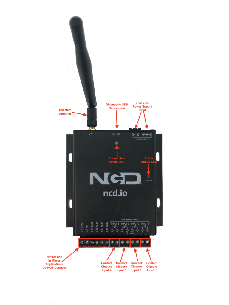
The Contact Closure input board is known as the Transmitter in this product. It has 4 dry contact closure inputs depicted in the photo to the right. There are additional screw terminals on the same connection block but those should not be used on this particular product.
The Power Status LED will illuminate when the board is connected to a sufficient power supply source
The Connection Status LED indicates the transmitter’s connection status with it’s mating receiver. If it is able to communicate with the receiver then this LED will flash Green, however if it is not able to communicate with the receiver this LED will flash red.
This board requires a power source greater than 9VDC and less than 32VDC. 12VDC is optimal but other voltages such as 9VDC or 24VDC may be used as well. The board will draw approximately 70 mA at 12VDC under normal operation.
A diagnostic USB port is available on the transmitter. This port can indicate some information in trouble shooting. The board will mount as a Virtual Serial/COM port on the connected computer OS. This is really only necessary for trouble shooting purposes.
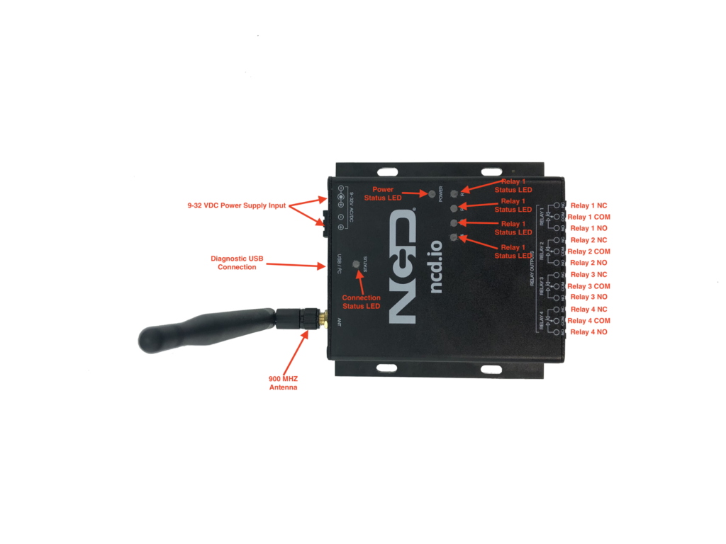
The relay output board is known as the Receiver in this product. It has 4 relay outputs depicted in the photo to the left. These relays are rated for 10 amps. Full specifications for these relays can be found in this Data Sheet.
The Power Status LED will illuminate when the board is connected to a sufficient power supply source
The Connection Status LED indicates the receiver’s connection status with it’s mating transmitter. If it is able to communicate with the transmitter then this LED will flash Green, however if it is not able to communicate with the transmitter this LED will flash red.
In the event communication is lost with the transmitter all relays on the receiver will de-energize after 1 second. This timeout duration can be altered by NCD staff at the request of the user, however it is not(at this time) user configurable.
This board requires a power source greater than 9VDC and less than 32VDC. 12VDC is optimal but other voltages such as 9VDC or 24VDC may be used as well. The board will draw approximately 70 mA at 12VDC under normal operation when all relays are off. Each energized relay will consume an additional 30mA at 12VDC.
A diagnostic USB port is available on the receiver. This port can indicate some information in trouble shooting. The board will mount as a Virtual Serial/COM port on the connected computer OS. This is really only necessary for trouble shooting purposes.