- Device Overview
- Frame Structure
- Configuration Mode
- Example Configuration Commands
- Error Code Descriptions
- Frame Checksum Calculation
Explore The Wireless Vibration, Ultrasound and Temperature Sensor Capabilities
Device Overview
Introducing NCD’s Wireless Vibration, Ultrasound and Temperature Sensor. Engineered for industrial predictive maintenance. They track 3-axis acceleration, vibration severity (RMS/Peak), temperature, and RPM. By capturing data up to 25.6kHz, they help detect mechanical faults (e.g., bearing wear, imbalance) before unexpected machine failures occur it also integrated ultrasound capabilities to capture high-frequency acoustic emissions.
This addition is critical because ultrasound detects the earliest stages of friction, lubrication starvation, and potential leaks long before detectable vibrations or temperature spikes occur. By combining both technologies, the sensor provides comprehensive visibility across the entire equipment degradation curve, allowing your team to identify and resolve anomalies weeks or months earlier than relying on vibration analysis alone.
Features:
- It Helps to Detect: Misalignment, Looseness, Imbalance, Bearing wear, Gearbox wear, Lubrication.
- Senses Vibration, Ultrasound and Temperature.
- Analyzes On-Device: FFT, Time-Domain Data, Overall, RPM, Uptime.
- Always-Listening Mode: Stays on to capture machines that cycle on and off.
- Small & lightweight for ease of installation.
- IP67 rated sealed enclosure for dust &
moisture protection. - D-cell battery for long-lasting operation.
- A versatile user-configurable sample rate for slow or fast-running machines.
- In-Built Machine Learning optimizes power consumption.
- Asset On-Time Calculator automatically tracks operational status.
- Hardware Accelerator enhances vibration sampling accuracy.
- Configurable Sample Rate – 100Hz to 25.6KHz
- Available Wireless Transmission Frequencies – 900Mhz, 868Mhz, and 2.4Ghz
- Supports MESH networking via DigiMesh
- Fully open Node-RED library for configuration and data ingestion
- No Monthly Cost.
- Total Data Owner Ship.
Frame Structure
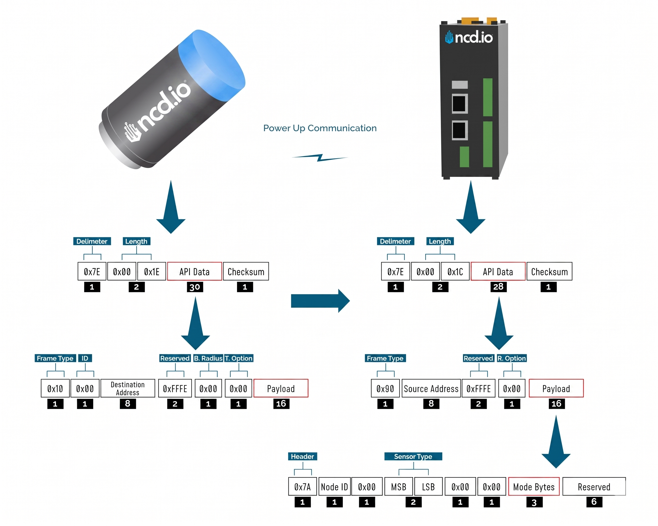
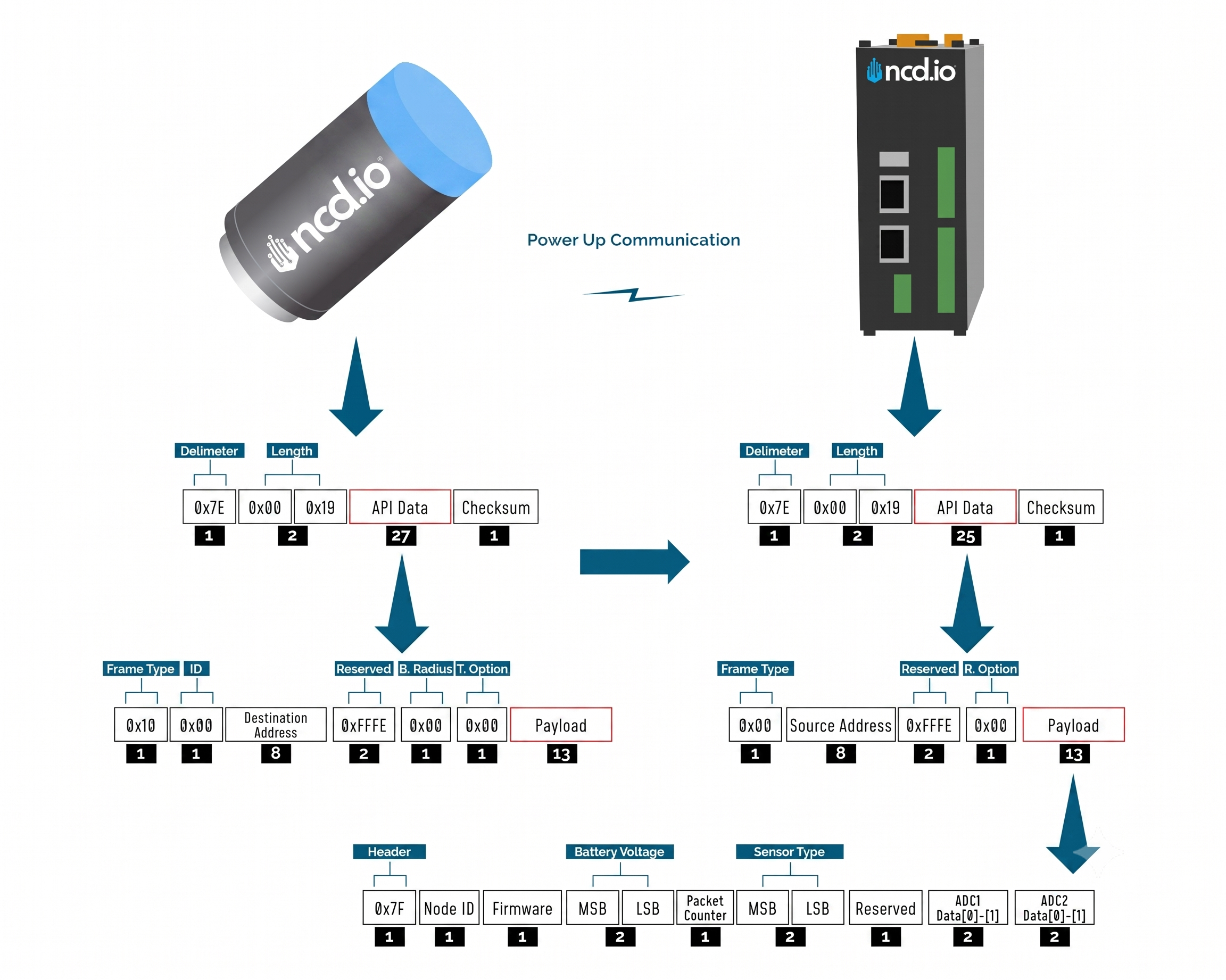
Frame Communication at Power Up
When the device powers up, depending on the mode it is going to work in, it will have a different Power Up Frame
Figure 3 provides an outline of the frame structure at Power Up, where the bytes highlighted in Red denote which mode the device has started in (Run, Configuration or Factory Default). You can look up the corresponding codes in Table 2.
If we further examine the Payload, we can use the Node ID and Sensor Type fields to determine the exact sensor that is sending the data.
A shown in the second column in Table 2, the sensor configures its PAN ID automatically depending upon the mode it is working in. During factory reset it sets the PAN ID to the value given in table therefore the factory reset frame will only be received if your Modem/Gateway PAN ID matches this ID. All 3 types of frames are shown in Figure 3, Figure 4 and Figure 5.
| Mode Type | PAN ID set by Sensor (ASCII) | Frame field | Offset (Payload section) | Value |
|---|---|---|---|---|
| Run | ID save by user / Default | Mode bytes | 7 | 0x52 |
| 8 | 0x55 | |||
| 9 | 0x4E | |||
| Configuration | 7BCD | Mode bytes | 7 | 0x50 |
| 8 | 0x47 | |||
| 9 | 0x4D | |||
| Factory Reset | 7FFF | Mode bytes | 7 | 0x50 |
| 8 | 0x55 | |||
| 9 | 0x4D |
Run Mode Frame
| Field | Number of bytes | Description |
|---|---|---|
| 7E 00 1C 90 00 13 A2 00 42 35 89 86 FF FE C2 7A 01 00 00 72 03 17 52 55 4E 00 00 00 00 00 00 79 | Example frame | |
| 0x7E | 1 | Delimiter |
| 0x001C | 2 | Length |
| 0x90 | 1 | Frame Type (Power Up) |
| 0x0013A20042536453 | 8 | Source Address |
| 0xFFFE | 2 | Reserved |
| 0xC2 | 1 | R. Option |
| 0x7A | 1 | Header with Power Up value |
| 0x00 | 1 | Node ID |
| 0x00 | 1 | Separator |
| 0x007F | 2 | Sensor Type |
| 0x0000 | 2 | Separator |
| 0x52554E | 3 | Mode Byte for Run Mode |
| 0x000000000000 | 6 | Reserved |
| 0x79 | 1 | Checksum |
Configuration Mode Frame
| Field | Number of bytes | Description |
|---|---|---|
| 7E 00 44 90 00 13 A2 00 42 35 89 86 FF FE C2 4F 00 00 17 0B 00 72 00 00 00 01 63 3D 00 7F FF 00 00 FF FF 01 0E 14 00 09 02 07 00 01 00 00 01 14 0A 0A 05 0C 00 03 00 00 00 FF FF 03 00 3C 01 00 00 64 01 00 00 00 00 5F | Example frame | |
| 0x7E | 1 | Delimiter |
| 0x0044 | 2 | Length |
| 0x90 | 1 | Frame Type |
| 0x0013A20042536453 | 8 | Source Address |
| 0xFFFE | 2 | Reserved |
| 0xC2 | 1 | R. Option |
| 4F | 1 | Header |
| 0000 | 2 | Reserved |
| 17 | 1 | Core Engine Version |
| 0B | 1 | Firmware Version |
| 007F | 2 | Sensor Type |
| 00000001 | 4 | Tx Life Counter |
| 633D00 | 3 | Hardware ID |
| 7FFF | 2 | Network ID |
| 0000FFFF | 4 | Destination Address |
| 00 | 1 | Node ID |
| 0E | 1 | Output Data Rate |
| 14 | 1 | Sampling Duration |
| 00 | 1 | Low Frequency Sampling Ratio |
| 09 | 1 | High Frequency Sampling Ratio |
| 02 | 1 | Full Scale Range |
| 00 | 1 | Axis Enabled |
| 04 | 1 | Sampling Interval |
| 01 | 1 | Filter Status |
| 03 | 1 | Operation Mode |
| 00 | 1 | Measurement Mode |
| 01 | 1 | Data On Request Timeout |
| 14 | 1 | Accelerometer Dead Band |
| 0A | 1 | Motion Detect Threshold |
| 0A | 1 | Acceleration Alert Threshold (LED) |
| 05 | 1 | Velocity Alert Threshold (LED) |
| 0C | 1 | Smart Accelerometer Threshold |
| 00 | 1 | LED Alert Mode |
| 03 | 1 | Time Domain Length (Accelerometer) |
| 00 | 1 | Auto Time Domain Interval |
| 0000FFFF | 4 | Auto Time Domain Destination Address |
| 03 | 1 | Smart Skip Mode |
| 003C | 2 | SYNC Rate |
| 01 | 1 | RPM Status |
| 1000 | 2 | Max Time Domain Transmission Samples (Accelerometer) |
| 64 | 1 | Motion to Sampling Delay |
| 01 | 1 | Max Number of Motion Transmissions per Interval |
| 00000000 | 4 | Probe Uptime |
| 1000 | 1 | Max Time Domain Transmission Samples (Ultrasound) |
| 5F | 1 | Checksum |
Factory Reset Mode Frame
| Field | Number of bytes | Description |
|---|---|---|
| 7E 00 1C 90 00 13 A2 00 42 53 64 53 FF FE C2 7A 00 00 00 72 00 00 50 55 4D 00 00 00 00 00 00 D1 | Example frame | |
| 0x7E | 1 | Delimiter |
| 0x001C | 2 | Length |
| 0x90 | 1 | Frame Type |
| 0x0013A20042536453 | 8 | Source Address |
| 0xFFFE | 2 | Reserved |
| 0xC2 | 1 | R. Option |
| 0x7A | 1 | Header |
| 0x00 | 1 | Node ID |
| 0x00 | 1 | Separator |
| 0x007F | 2 | Sensor Type |
| 0x0000 | 2 | Separator |
| 0x50554D | 3 | Mode Byte for Factory Reset Mode |
| 0x000000000000 | 6 | Reserved |
| 0xD1 | 1 | Checksum |
Sync Check In Frame
| Field | Number of bytes | Description |
|---|---|---|
| 7E 00 44 90 00 13 A2 00 42 35 89 86 FF FE C2 6F 00 00 17 0B 00 72 00 00 00 02 63 3D 00 7F FF 00 00 FF FF 01 0E 14 00 09 02 07 00 01 00 00 01 14 0A 0A 05 0C 00 03 00 00 00 FF FF 03 00 3C 01 00 00 64 01 00 00 00 00 3E | Example frame | |
| 0x7E | 1 | Delimiter |
| 0x001C | 2 | Length |
| 0x90 | 1 | Frame Type |
| 0x0013A20042536453 | 8 | Source Address |
| 0xFFFE | 2 | Reserved |
| 0x00 | 1 | R. Option |
| 6F | 1 | Header |
| 0000 | 2 | Reserved |
| 17 | 1 | Core Engine Version |
| 0B | 1 | Firmware Version |
| 007F | 2 | Sensor Type |
| 00000001 | 4 | Tx Life Counter |
| 633D00 | 3 | Hardware ID |
| 7FFF | 2 | Network ID |
| 0000FFFF | 4 | Destination Address |
| 00 | 1 | Node ID |
| 0E | 1 | Output Data Rate |
| 14 | 1 | Sampling Duration |
| 00 | 1 | Low Frequency Sampling Ratio |
| 09 | 1 | High Frequency Sampling Ratio |
| 02 | 1 | Full Scale Range |
| 00 | 1 | Axis Enabled |
| 04 | 1 | Sampling Interval |
| 01 | 1 | Filter Status |
| 03 | 1 | Operation Mode |
| 00 | 1 | Measurement Mode |
| 01 | 1 | Data On Request Timeout |
| 14 | 1 | Accelerometer Dead Band |
| 0A | 1 | Motion Detect Threshold |
| 0A | 1 | Acceleration Alert Threshold (LED) |
| 05 | 1 | Velocity Alert Threshold (LED) |
| 0C | 1 | Smart Accelerometer Threshold |
| 00 | 1 | LED Alert Mode |
| 03 | 1 | Time Domain Length (Accelerometer) |
| 00 | 1 | Auto Time Domain Interval |
| 0000FFFF | 4 | Auto Time Domain Destination Address |
| 03 | 1 | Smart Skip Mode |
| 003C | 2 | SYNC Rate |
| 01 | 1 | RPM Status |
| 1000 | 2 | Max Time Domain Transmission Samples (Accelerometer) |
| 64 | 1 | Motion to Sampling Delay |
| 01 | 1 | Max Number of Motion Transmissions per Interval |
| 00000000 | 4 | Probe Uptime |
| 1000 | 1 | Max Time Domain Transmission Samples (Ultrasound) |
| 3E | 1 | Checksum |
Sync Acknowledgment Frame
| Field | Number of bytes | Description |
|---|---|---|
| 7E 00 44 90 00 13 A2 00 42 35 89 86 FF FE C2 5F 00 F4 17 0B 00 7F 00 00 00 73 63 3D 00 7F FF 00 00 FF FF 01 0E 14 00 09 02 07 00 01 03 00 01 14 0A 0A 05 0C 00 03 00 00 00 FF FF 03 00 3C 01 10 00 64 01 00 00 00 00 D6 | Example frame | |
| 0x7E | 1 | Delimiter |
| 0x001C | 2 | Length |
| 0x90 | 1 | Frame Type |
| 0x0013A20042536453 | 8 | Source Address |
| 0xFFFE | 2 | Reserved |
| 0x00 | 1 | R. Option |
| 5F | 1 | Header |
| 0000 | 2 | Reserved |
| 17 | 1 | Core Engine Version |
| 0B | 1 | Firmware Version |
| 007F | 2 | Sensor Type |
| 00000001 | 4 | Tx Life Counter |
| 633D00 | 3 | Hardware ID |
| 7FFF | 2 | Network ID |
| 0000FFFF | 4 | Destination Address |
| 00 | 1 | Node ID |
| 0E | 1 | Output Data Rate |
| 14 | 1 | Sampling Duration |
| 00 | 1 | Low Frequency Sampling Ratio |
| 09 | 1 | High Frequency Sampling Ratio |
| 02 | 1 | Full Scale Range |
| 00 | 1 | Axis Enabled |
| 04 | 1 | Sampling Interval |
| 01 | 1 | Filter Status |
| 03 | 1 | Operation Mode |
| 00 | 1 | Measurement Mode |
| 01 | 1 | Data On Request Timeout |
| 14 | 1 | Accelerometer Dead Band |
| 0A | 1 | Motion Detect Threshold |
| 0A | 1 | Acceleration Alert Threshold (LED) |
| 05 | 1 | Velocity Alert Threshold (LED) |
| 0C | 1 | Smart Accelerometer Threshold |
| 00 | 1 | LED Alert Mode |
| 03 | 1 | Time Domain Length (Accelerometer) |
| 00 | 1 | Auto Time Domain Interval |
| 0000FFFF | 4 | Auto Time Domain Destination Address |
| 03 | 1 | Smart Skip Mode |
| 003C | 2 | SYNC Rate |
| 01 | 1 | RPM Status |
| 1000 | 2 | Max Time Domain Transmission Samples (Accelerometer) |
| 64 | 1 | Motion to Sampling Delay |
| 01 | 1 | Max Number of Motion Transmissions per Interval |
| 00000000 | 4 | Probe Uptime |
| 1000 | 1 | Max Time Domain Transmission Samples (Ultrasound) |
| 5F | 1 | Checksum |
UPTHWRN Mode Frame
| Field | Number of bytes | Description |
|---|---|---|
| 7E 00 1C 90 00 13 A2 00 42 53 64 53 FF FE C2 7F 00 0E 03 E9 12 00 72 00 55 50 54 48 57 52 4E 7A | Example frame | |
| 0x7E | 1 | Delimiter |
| 0x001C | 2 | Length |
| 0x90 | 1 | Frame Type |
| 0x0013A1004158C1CB | 8 | Source Address |
| 0xFFFE | 2 | Reserved |
| 0x00 | 1 | R. Option |
| 0x7F | 1 | Header |
| 0x00 | 1 | Node ID |
| 0x0E | 1 | Firmware Version |
| 0x03E9 | 2 | Battery Voltage |
| 0x12 | 1 | Packet Counter |
| 0x007F | 2 | Sensor Type |
| 0x00 | 1 | Reserved |
| 0x5550544857524E | 7 | Mode Byte for UPTHWRN Mode |
| 0x7A | 1 | Checksum |
MOFF Mode Frame
| Field | Number of bytes | Description |
|---|---|---|
| 7E 00 18 90 00 13 A1 00 41 58 C1 CB FF FE C1 7C 01 6F 00 72 08 FF 4D 4F 46 46 00 E9 | Example frame | |
| 0x7E | 1 | Delimiter |
| 0x0018 | 2 | Length |
| 0x90 | 1 | Frame Type |
| 0x0013A1004158C1CB | 8 | Source Address |
| 0xFFFE | 2 | Reserved |
| 0xC1 | 1 | R. Option |
| 0x7C | 1 | Header |
| 0x00 | 1 | Node ID |
| 0x6F | 1 | Separator |
| 0x03E9 | 2 | Battery Voltage |
| 0x12 | 1 | Packet Counter |
| 0x007F | 2 | Sensor Type |
| 0x08FF4D | 3 | Reserved |
| 0x4F464600 | 7 | Mode Byte for MOFF Mode |
| 0xE9 | 1 | Checksum |
Assertion Reason Frame
| Field | Number of bytes | Description |
|---|---|---|
| 77 00 00 00 6E 00 00 00 08 C3 61 70 70 5F 73 74 61 72 74 5F 66 6C 79 5F 74 69 6D 65 72 00 00 00 00 00 00 00 00 00 | Example frame | |
| 0x77 | 1 | Delimiter |
| 0x00 | 2 | Node ID |
| 0x0000 | 2 | Reserved |
| 0x007F | 2 | Sensor Type |
| 0x000008C3 | 4 | Line Number |
| 0x00 | Function Name |
Sensor Data Frame
Run mode is the default mode of operation of this sensor. In this mode, the sensor sends periodic packets with the sensor measurement data. During the time it is not sending it enters deep-sleep to conserve power. The sensor’s X-bee Radio module operates in API mode and sends packets to the saved destination address on the network specified by the saved PAN ID. Figure 4 illustrates the API transmission/reception procedure.
As this sensor has three possible frame structures for the Processed, Time-Domain (Accelerometer) and Time-Domain (Ultrasound) mode, we are detailing each one below:
Processed Data Frame
| Frame Field | Offset (Payload section) | Fixed Value (if any) | Length | Description |
|---|---|---|---|---|
| Header | 0 | 0x7F | 1 | Header to differentiate various types of packets |
| Node ID | 1 | 0x00 | 1 | Node ID to differentiate up to 256 nodes in a network. User configurable values |
| Firmware | 2 | 0x01 | 1 | Used to determine firmware version programmed in the device |
| Battery Voltage | MSB 3 | 0x03 | 2 | Battery Voltage = 0.00322*(03*FF+FE) |
| LSB 4 | 0xFE | Battery Voltage = ((Battery Voltage MSB x 256) + Battery Voltage LSB) x 0.00322 V | ||
| Packet Counter | 5 | - | 1 | It is an 8-bit counter that increments with each packet transmission. It can be used to detect missing packets |
| Sensor Type | MSB 6 | 0x00 | 2 | Two bytes to determine sensor type. It can be used in conjunction with Node ID to create sensor networks of up to 256 nodes for a single type of sensor and multiple such networks can coexist and can be differentiated in processing software on PC end. |
| LSB 7 | 0x7F | Sensor Type 127 | ||
| Error/Reserved byte | 8 | 0x00 | 1 | Bit 7: Reserved Bit 6: Reserved Bit 5: Reserved Bit 4: 1 - Motion Report, 0 - Regular report Bit 3: Reserved Bit 2: Reserved Bit 1: Probe 1 Data invalid Bit 0: Reserved |
| In Processed Packet. Bit 4: Message Type: - 1: Motion Report - 0: Regular Report |
||||
| Sensor Data | 9/ Data[0] | 0x00 | 1 | Mode of Operation: 0x00 - Processed 0x01 - Raw 0x02 - Processed + On Demand 0x03 - Smart |
| Output Data Rate | 10/ Data[0] | - | 1 | Vibration Sample Rate: 0x07 - 100Hz 0x08 - 200Hz 0x09 - 400Hz 0x0A - 800Hz 0x0B - 1600Hz 0x0C - 3200Hz 0x0D - 6400Hz 0x0E - 12800Hz 0x0F - 25600Hz |
| Temperature | 11/ Data[0] | - | 2 | |
| 12/ Data[1] | - | Temperature in Celsius = (Data[0] * FF + Data[1]) / 100 | ||
| RMS ACC in X Axis in mg | 13/ Data[0] | - | 2 | rms_acc_x_mg value |
| 14/ Data[1] | - | rms_acc_x_mg = (Data[0] * FF + Data[1]) / 1000 | ||
| MAX ACC in X Axis in mg | 15/ Data[0] | - | 2 | max_acc_x_mg value |
| 16/ Data[1] | - | max_acc_x_mg = (Data[0] * FF + Data[1]) / 1000 | ||
| RMS Velocity in X Axis in mm/sec | 17/ Data[0] | - | 2 | rms_vel_x_mm_sec value |
| 18/ Data[1] | - | rms_vel_x_mm_sec = (Data[0] * FF + Data[1]) / 100 | ||
| RMS Displacement in X Axis in mm | 19/ Data[0] | - | 2 | rms_disp_x_mm value |
| 20/ Data[1] | - | rms_disp_x_mm = (Data[0] * FF + Data[1]) / 100 | ||
| Frequency of Highest Peak in X direction | 21/ Data[0] | - | 2 | X1 Hz Value |
| 22/ Data[1] | - | X1_Hz = (Data[0] * FF + Data[1]) | ||
| Frequency of Second Highest Peak in X direction | 23/ Data[0] | - | 2 | X2_Hz Value |
| 24/ Data[1] | - | X2_Hz = (Data[0] * FF + Data[1]) | ||
| Frequency of Third Highest Peak in X direction | 25/ Data[0] | - | 2 | X3_Hz Value |
| 26/ Data[1] | - | X3_Hz = (Data[0] * FF + Data[1]) | ||
| RMS ACC in Y Axis in mg | 27/ Data[0] | - | 2 | rms_acc_y_mg value |
| 28/ Data[1] | - | rms_acc_y_mg = (Data[0] * FF + Data[1]) / 1000 | ||
| MAX ACC in Y Axis in mg | 29/ Data[0] | - | 2 | max_acc_y_mg value |
| 30/ Data[1] | - | max_acc_y_mg = (Data[0] * FF + Data[1]) / 1000 | ||
| RMS Velocity in Y Axis in mm/sec | 31/ Data[0] | - | 2 | rms_vel_y_mm_sec value |
| 32/ Data[1] | - | rms_vel_y_mm_sec = (Data[0] * FF + Data[1]) / 100 | ||
| RMS Displacement in Y Axis in mm | 33/ Data[0] | - | 2 | rms_disp_y_mm value |
| 34/ Data[1] | - | rms_disp_y_mm = (Data[0] * FF + Data[1]) / 100 | ||
| Frequency of Highest Peak in Y direction | 35/ Data[0] | - | 2 | Y1 Hz Value |
| 36/ Data[1] | - | Y1_Hz = (Data[0] * FF + Data[1]) | ||
| Frequency of Second Highest Peak in Y direction | 37/ Data[0] | - | 2 | Y2_Hz Value |
| 38/ Data[1] | - | Y2_Hz = (Data[0] * FF + Data[1]) | ||
| Frequency of Third Highest Peak in Y direction | 39/ Data[0] | - | 2 | Y3_Hz Value |
| 40/ Data[1] | - | Y3_Hz = (Data[0] * FF + Data[1]) | ||
| RMS ACC in Z Axis in mg | 41/ Data[0] | - | 2 | rms_acc_z_mg value |
| 42/ Data[1] | - | rms_acc_z_mg = (Data[0] * FF + Data[1]) / 1000 | ||
| MAX ACC in Z Axis in mg | 43/ Data[0] | - | 2 | max_acc_z_mg value |
| 44/ Data[1] | - | max_acc_z_mg = (Data[0] * FF + Data[1]) / 1000 | ||
| RMS Velocity in Z Axis in mm/sec | 45/ Data[0] | - | 2 | rms_vel_z_mm_sec value |
| 46/ Data[1] | - | rms_vel_z_mm_sec = (Data[0] * FF + Data[1]) / 100 | ||
| RMS Displacement in Z Axis in mm | 47/ Data[0] | - | 2 | rms_disp_z_mm value |
| 48/ Data[1] | - | rms_disp_z_mm = (Data[0] * FF + Data[1]) / 100 | ||
| Frequency of Highest Peak in Z direction | 49/ Data[0] | - | 2 | Z1 Hz Value |
| 50/ Data[1] | - | Z1_Hz = (Data[0] * FF + Data[1]) | ||
| Frequency of Second Highest Peak in Z direction | 51/ Data[0] | - | 2 | Z2_Hz Value |
| 52/ Data[1] | - | Z2_Hz = (Data[0] * FF + Data[1]) | ||
| Frequency of Third Highest Peak in Z direction | 53/ Data[0] | - | 2 | Z3_Hz Value |
| 54/ Data[1] | - | Z3_Hz = (Data[0] * FF + Data[1]) | ||
| Revolutions Per Minute (RPM) | 55/ Data[0] | - | 2 | Revolutions Per Minute Value |
| 56/ Data[1] | - | RPM = (Data[0] * FF + Data[1]) | ||
| Ultrasonic RMS dBuV | 57/ Data[0] | - | ||
| 58/ Data[1] | 2 | Ultrasonic RMS = (Data[0] * FF + Data[1]) | ||
| Ultrasonic Peak to Peak dBuV | 59/ Data[0] | - | ||
| 60/ Data[1] | - | 2 | Ultrasonic Peak to Peak = (Data[0] * FF + Data[1]) | |
| Crest Factor | 61/ Data[0] | - | ||
| 602/ Data[1] | - | 2 | Crest Factor = (Data[0] * FF + Data[1]) / 100 |
Time Domain (Accelerometer) Data Frame
| Frame Field | Offset (Payload section) | Fixed Value (if any) | Length | Description |
|---|---|---|---|---|
| Header | 0 | 0x7F | 1 | Header to differentiate various types of packets |
| Node ID | 1 | 0x00 (Factory Default) | 1 | Node ID to differentiate up to 256 nodes in a network. User configurable values |
| Firmware | 2 | 0x01 | 1 | Used to determine firmware version programmed in the device |
| Battery Voltage | MSB 3 | 0x03 | 2 | Battery Voltage = 0.00322*(03*FF+FE) |
| LSB 4 | 0xFE | Battery Voltage = ((Battery Voltage MSB x 256) + Battery Voltage LSB) x 0.00322 V | ||
| Packet Counter | 5 | - | 1 | It is an 8-bit counter that increments with each packet transmission. It can be used to detect missing packets |
| Sensor Type | MSB 6 | 0x00 | 2 | Two bytes to determine sensor type. It can be used in conjunction with Node ID to create sensor networks of up to 256 nodes for a single type of sensor and multiple such networks can coexist and can be differentiated in processing software on PC end. |
| LSB 7 | 0x7F | Sensor Type 127 | ||
| Error/Reserved byte | 8 | 0x00 | 1 | Bit 1: Validity of Data for sensor: - 0: Data is valid. - 1: Error in accessing sensor |
| In Time Domain Data (RAW) Packet. Bit 4: Message Type: - 1: Motion Report - 0: Regular Report |
||||
| Bit 5: Source Type - 0: Accelerometer Sensor - 1: Ultrasound Sensor |
||||
| Sensor Data | 9/ Data[0] | 0x01 | 1 | Mode of Operation: 00 - Processed 01 - Raw 02 - Processed + On Demand 03 - Smart |
| Output Data Rate | 10/ Data[0] | - | Output Data Rate Value | |
| 11/Data[1] | - | 2 | ODR = (Data[0] * FF + Data[1]) | |
| Full Scale Range and Eabled Axis | 12/Data[0] | - | 1 | Three MSB bit of the Axis byte to indicate FSR And 3 LSB bits indicates Axis |
| Hour | 13/Data[0] | - | 1 | Hour = Data[0] |
| Minute | 14/Data[0] | - | 1 | Minute = Data[0] |
| Device Temperature | 15/Data[0] | - | Device Temperature Value | |
| 16/Data[1] | - | 2 | Temperature = (Data[0] * FF + Data[1]) / 100 | |
| Total Number of RF Packets | 17/Data[0] | - | Total Number of RF Packets Value | |
| 18/Data[1] | - | 2 | Total Number of RF Packets = ((Data[0] << 8) + Data[1]) | |
| Current Packet Count value | 19/Data[0] | - | Current Packet Count value | |
| 20/Data[1] | - | 2 | Current Packet Count = ((Data[0] << 8) + Data[1]) | |
| Time Domain Data Packets | - | - | - | - |
| X1-Axis RAW ACC Data | - | - | - | X1= (01*0xFF+ 0xDE)*FSR coefficient |
| Y1-Axis RAW ACC Data | - | - | - | Y1= (01*0xFF+ 0x7A)*FSR coefficient |
| Z1-Axis RAW ACC Data | - | - | - | Z1= (3F*0xFF+ 0x8B)*FSR coefficient |
Time Domain (Ultrasound) Data Frame
| Frame Field | Offset (Payload section) | Fixed Value (if any) | Length | Description |
|---|---|---|---|---|
| Header | 0 | 0x7F | 1 | Header to differentiate various types of packets |
| Node ID | 1 | 0x00 (Factory Default) | 1 | Node ID to differentiate up to 256 nodes in a network. User configurable values |
| Firmware | 2 | 0x01 | 1 | Used to determine firmware version programmed in the device |
| Battery Voltage | MSB 3 | 0x03 | 2 | Battery Voltage = 0.00322*(03*FF+FE) |
| LSB 4 | 0xFE | Battery Voltage = ((Battery Voltage MSB x 256) + Battery Voltage LSB) x 0.00322 V | ||
| Packet Counter | 5 | - | 1 | It is an 8-bit counter that increments with each packet transmission. It can be used to detect missing packets |
| Sensor Type | MSB 6 | 0x00 | 2 | Two bytes to determine sensor type. It can be used in conjunction with Node ID to create sensor networks of up to 256 nodes for a single type of sensor and multiple such networks can coexist and can be differentiated in processing software on PC end. |
| LSB 7 | 0x7F | Sensor Type 127 | ||
| Error/Reserved byte | 8 | 0x00 | 1 | Bit 1: Validity of Data for sensor: - 0: Data is valid. - 1: Error in accessing sensor |
| In Time Domain Data (RAW) Packet. Bit 4: Message Type: - 1: Motion Report - 0: Regular Report |
||||
| Bit 5: Source Type - 0: Accelerometer Sensor - 1: Ultrasound Sensor |
||||
| Sensor Data | 9/ Data[0] | 0x01 | 1 | Mode of Operation: 00 - Processed 01 - Raw 02 - Processed + On Demand 03 - Smart |
| Output Data Rate | 10/ Data[0] | - | ||
| 11/Data[1] | - | |||
| 12/Data[2] | - | 3 | Output Data Rate = ((Data[2] << 16) + ((Data[0] << 8) + Data[1]) Note: Double-check Byte position to decode |
|
| Temperature | 13/Data[0] | - | ||
| 14/Data[1] | 2 | Temperature = ((Data[0] << 8) + Data[1]) / 100 | ||
| Hour | 15/Data[0] | - | 1 | Hour = Data[0] |
| Minute | 16/Data[0] | - | 1 | Minute = Data[0] |
| Total Nomber of RF Packets | 17/Data[0] | - | ||
| 18/Data[1] | - | 2 | Total Number of RF Packets = ((Data[0] << 8) + Data[1]) | |
| Current Packet Count value | 19/Data[0] | - | ||
| 20/Data[1] | - | 2 | Current Packet Count = ((Data[0] << 8) + Data[1]) | |
| Time Domain Data Packets (Ultrasound) | 21/Data[0] | - | ||
| n/Data[n] | - | n |
Time Domain Request Commands
The On-Request Time Domain (Raw) Data Transmission empowers users with precise control. After receiving a processed data transmission, users can send a specific command to request the raw data. This method is ideal for creating custom logic based on various conditions—such as vibration thresholds, time values, or asynchronous events—to strategically trigger raw data requests.
Accelerometer
For regular Time-Domain Accelerometer Data Request:
7E 00 15 10 01 00 00 00 00 00 00 FF FF FF FE 00 00 F4 4F 00 00 50 13 01 4C
Complete Payload:
F4 4F 00 00 50 13 01
Ultrasound
For Time-Domain Ultrasound Data Request:
7E 00 14 10 01 00 00 00 00 00 00 FF FF FF FE 00 00 F4 4F 00 00 65 5D EE
Complete Payload:
F4 4F 00 00 65 5D
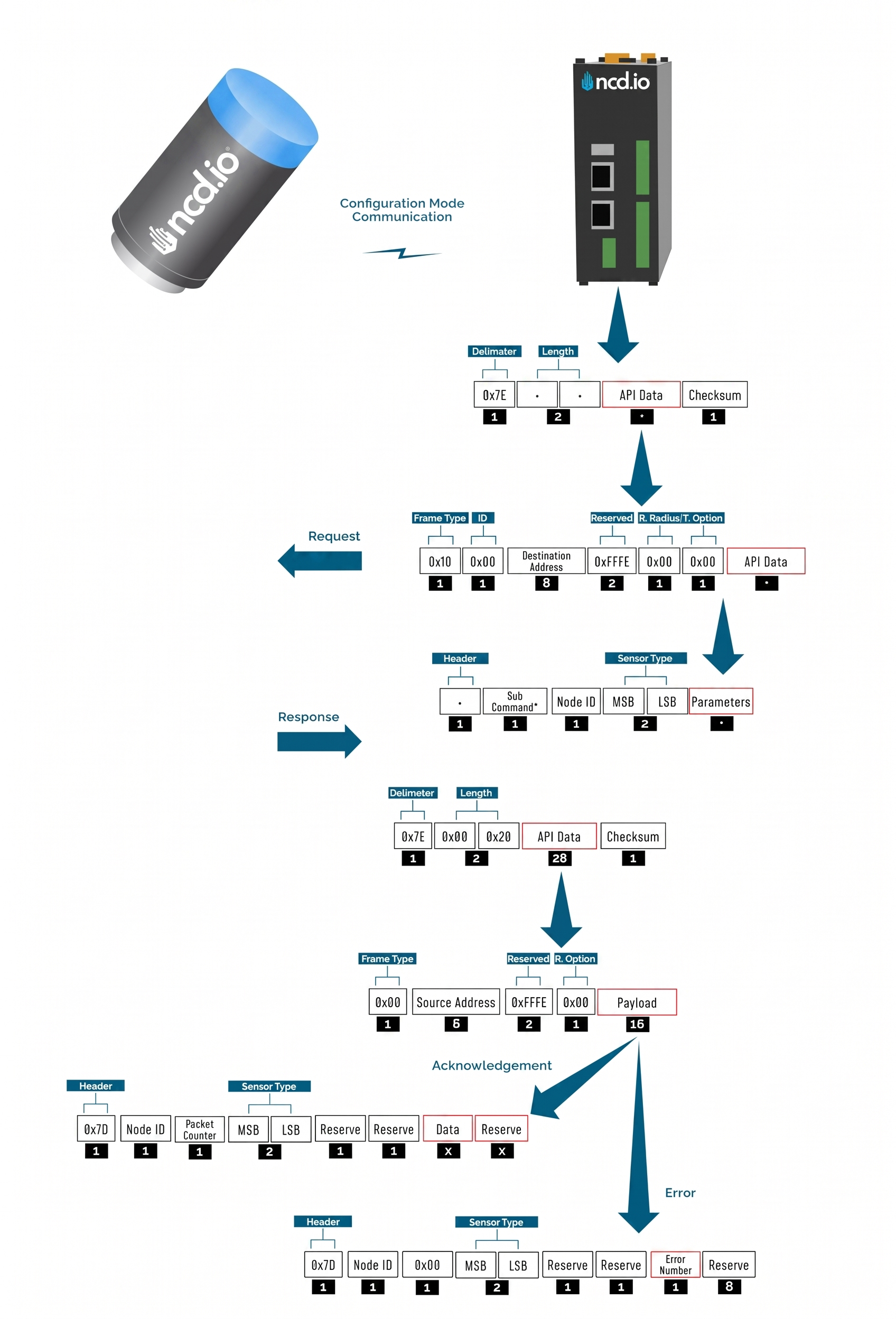
Configuration Mode
Manual Configuration Mode (enter via CFG key press for 7 seconds at power up) is intended to setup the device over the wireless link, you can change parameter values that are subject to change via downlink master command.
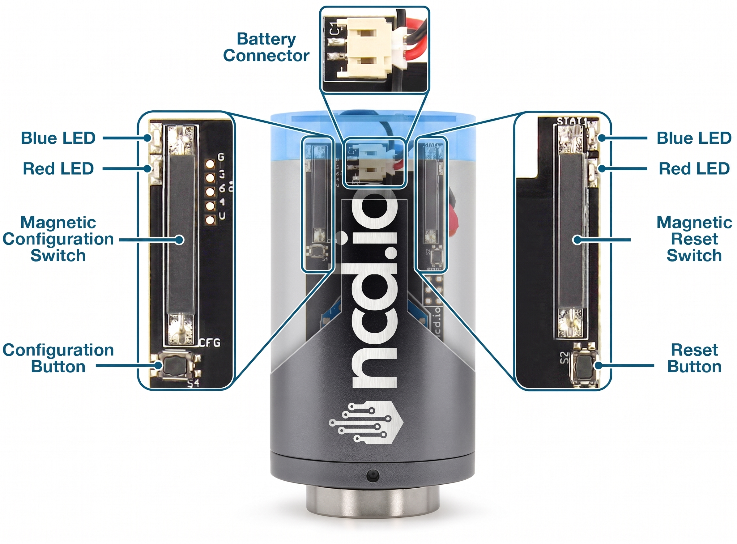
To put an NCD.io wireless sensor into configuration mode, you can do the following:
Using Button
1. Press and release the RESET button
2. Immediately press and hold the CONFIGURATION button
3. Hold the CONFIGURATION button for about 5–8 seconds
4. Release the CONFIGURATION button
Using Magnetic
1. Bring the magnet into close proximity to the designated RESET point on the device housing, then remove it immediately.
2. Immediately place the magnet against the designated CONFIGURATION activation point on the device housing and hold it in place.
3. Maintain the magnet’s position at the CONFIGURATION point for approximately 5 to 8 seconds.
4. Remove the magnet from the CONFIGURATION position.
In configuration mode, the device sets its X-bee pan id to 7BCD. Also, the destination address used by the sensor is extracted from the incoming packet (source address). This ensures that once you put a device in configuration mode you just need to change the PAN ID you are sending to in your Modem/Gateway to match with the sensor and start configuring your device.
A standard configuration packet and its fields are explained in Figure 5. Its possible responses are also shown. The complete set of commands supported by this sensor are shown in тхе Appendix, these can be used in the Parameters field of the Payload section. The sensor responds to these commands with an acknowledgement if the process completed successfully or with an error if it failed to setup a parameter. The respective Data and Reserve section length and values are shown in Table 6 for the case of acknowledgement. In the case of error, the reserved section will be fixed and not used, while the Error number byte will determine the type of error returned. These errors are in a separate section in the Appendix.
Example Configuration Commands
The following is an example on how to read and change some of the parameters that affect the operation of the NCD Sensor.
Master Command
Lorem ipsum dolor sit amet, consectetur adipiscing elit. Ut elit tellus, luctus nec ullamcorper mattis, pulvinar dapibus leo.
					7E 00 38 10 01 00 00 00 00 00 00 FF FF FF FE 00 00 6C 00 00 7F FF 00 00 FF FF 00 0E 28 00 09 02 07 04 01 03 00 01 14 0A
0A 05 0C 00 03 00 00 00 00 00 03 00 3C 01 10 00 64 01 00 C9
Complete Payload
					6C 00 00 7F FF 00 00 FF FF 00 0E 28 00 09 02 07 04 01 03 00 01 14 0A 0A 05 0C 00 03 00 00 00 00 00 03 00 3C 01 10 00 64
01 00
Payload Description
| Index | Byte | Size (bytes) | Setting | Valid Options | Description |
|---|---|---|---|---|---|
| [0] | 6C | 1 | Header | ||
| [1:2] | 00 00 | 2 | Reserved | ||
| [3:4] | 7F FF | 2 | Network ID | 0x00 -- 0x7FFF | Network ID Valid Range: 0-0x7FFF. |
| [5:8] | 00 00 FF FF | 4 | Destination Address | Default value: 0000FFFF for Broadcast Mode Example of targeted address: 41D5EC37 | Sets the Destination Address of the sensor. The sensor will send Run mode Data packets to this Address |
| [9] | 00 | 1 | Node ID | 0x00 -- 0xFF | Sets the Device node ID and Data Transmission Interval. The node id value can go from 0-255 and The Data transmission value can go from 3-0xFFFFFF Seconds |
| [10] | 0E | 1 | Output Data Rate | 0x07--100Hz 0x08--200Hz 0x09--400Hz 0x0A--800Hz 0x0B--1600Hz 0x0C--3200Hz 0x0D--6400Hz 0x0E--12800Hz 0x0F--25600Hz | This would determine how many samples the output data has, which is directly related to the highest frequency components that can be measured. In accordance with the Nyquist equation: f_max = ODR/2.56 Hz Note: Increasing the ODR to 25600Hz introduces significant noise in the vibration data as it allows more frequencies in the resulting data. |
| [11] | 28 | 1 | Sampling Duration | 0x01 -- 0x64 | Set the amount of time which the samples are taken. Note: The sampling duration depends on the ODR. 1= 50msec, 2= 100msec |
| [12] | 00 | 1 | Low Frequency Sampling Ratio | 0x00 -- 4 Filter Coefficient 0x01 -- 8 Filter Coefficient 0x02 -- 16 Filter Coefficient 0x03 -- 32 Filter Coefficient 0x04 -- 64 Filter Coefficient 0x05 -- 128 Filter Coefficient 0x06 -- 256 Filter Coefficient 0x07 -- 512 Filter Coefficient 0x08 -- 1024 Filter Coefficient 0x09 -- 2048 Filter Coefficient | This setting will set the LPF freq to ODR divided by Selected Value Example: ODR = 800 and Filter Coefficient = 4 LPF freq = 800/4 = 200Hz |
| [13] | 09 | 1 | High Frequency Sampling Ratio | 0x00 -- 4 Filter Coefficient 0x01 -- 8 Filter Coefficient 0x02 -- 16 Filter Coefficient 0x03 -- 32 Filter Coefficient 0x04 -- 64 Filter Coefficient 0x05 -- 128 Filter Coefficient 0x06 -- 256 Filter Coefficient 0x07 -- 512 Filter Coefficient 0x08 -- 1024 Filter Coefficient 0x09 -- 2048 Filter Coefficient | This setting will set the HPF freq to ODR divided by Selected Value Example: ODR = 800 and Filter Coefficient = 64 HPF freq = 800/64 = 12.5Hz |
| [14] | 02 | 1 | Full Scale Range | 0x00 -- +/- 2g 0x01 -- +/- 4g 0x02 -- +/- 8g 0x03 -- +/- 16g 0x04 -- +/- 32g 0x05 -- +/- 64g | Set how large of a range the device can measure acceleration in. Example: +/- 8g would mean that it would measure at most up to 8g and down to -8g. |
| [15] | 07 | 1 | Axis Enabled | ||
| [16] | 04 | 1 | Sampling Interval | 0x08 -- Every 1 minutes 0x00 -- Every 5 minutes 0x01 -- Every 10 minutes 0x02 -- Every 15 minutes 0x03 -- Every 20 minutes 0x04 -- Every 30 minutes 0x05 -- Every 60 minutes 0x06 -- Every 120 minutes 0x07 -- Every 180 minutes | Set how often will the sensor transmit measurement data. Note: For this sensor, this value functions as the sampling interval rather than a traditional delay. |
| [17] | 01 | 1 | Filter Status | 0x01 -- Enable 0x00 -- Disable | Enable/Disable built-in filters |
| [18] | 03 | 1 | Operation Mode | 0x00 -- Processed Mode 0x01 -- Raw Mode 0x02 -- Processed + Raw on Request 0x03 -- Smart Mode | • Processed: FFT is performed by the sensor and the measurement data is transmitted in condensed form (both time and frequency parameters). • Time Domain (Raw): The Time Domain (Raw) data is gathered and transmitted and it is up to the client to perform the FFT if needed. This is a very large data packet. • Processed + Raw on demand: Transmit Processed data at intervals, with the option to request a Time Domain (Raw) data packet. • Smart: Transmit Processed data at intervals and Time Domain (Raw) data on request, with auto Time Domain (Raw) data transmission option. Option to triggers on RMS acceleration exceeding thresholds on X, Y, Z axes, with smart skip to limit sends when vibrations are low. WARNING: If Mode is set to Time Domain (Raw) data or Auto Time Domain (Raw) data (in Smart Mode) it is recommended to also set the Destination Address (Auto Raw Destination Address in Smart mode) configuration to the address of your Receiver/Gateway. |
| [19] | 00 | 1 | Measurement Mode | ||
| [20] | 01 | 1 | Data on request timeout | 0x00 to 0x0A | Set how long device will stay awake and wait for Time Domain (Raw) request from command. |
| [21] | 14 | 1 | Accelerometer deadband | Valid Range: 0x00 -- 0xFF | |
| [22] | 0A | 1 | Motion detect | Valid Range: 0x00 -- 0x28 | The sensor will wake up and take samples when vibration goes above this threshold(Set threshold 400mg, Multiple of 50mg) |
| [23] | 0A | 1 | Acceleration alert threshold | Valid Range: 0x00 -- 0xFF | Set the minimum acceleration value to make LED indicator red.This will be an integer value that increments the threshold by 50mg. A value of 1 means turn the LED red if acceleration is above 50mg, 2 means 100mg, etc.**Only applies if LED Alert Mode is set to Acceleration.RED Alert Led Will Blink If the RMS acceleration readings go above this threshold(Set threshold 400mg, Multiple of 50mg) |
| [24] | 05 | 1 | Velocity Alert | Valid Range: 0x00 -- 0xFF | Set the minimum velocity value to make LED indicator red.This will be an integer value that increments the threshold by 2mm/second. A value of 1 means turn the LED red if velocity is above 2mm/sec, 2 means 4mm/second, etc.**Only applies if LED Alert Mode is set to Velocity.RED Alert Led Will Blink If the RMS Velocity readings go above this threshold(Set threshold 20mm/sec, Multiple of 2mm/sec) |
| [25] | 0C | 1 | Smart accelerometer threshold | Valid Range: 0x00 -- 0xFFFE | If RMS acceleration is above this in any axis, it will send data. This will be an integer value that increments the interrupt threshold by 50 mg. A value of 1 means to wake the sensor if acceleration is above 50 mg, 2 means 100 mg, etc. |
| [26] | 00 | 1 | Alert mode | 0x00 -- Acceleration 0x01 -- Velocity | Alert LED will blink if readings go above set threshold |
| [27] | 03 | 1 | Raw packet length | 0x00 -- 55 Bytes 0x01 -- 100 Bytes 0x02 -- 150 Bytes 0x03 -- 180 Bytes | Set the amount of Time Domain Data included in each RAW transmission sent by the sensor. |
| [28] | 00 | 1 | Auto Time-Domain interval | Valid Range: 0x00 -- 0xFF | The interval is determined by the sample interval. If the value is set to 1 and the sample interval is 10 minutes, raw data will be sent every 10 minutes. If the value is set to 5, raw data will be sent every 50 minutes. |
| [29:32] | 00 00 00 00 | 4 | Auto Time-Domain destination address | Valid Range: 0x00 -- 0xFFFFFFFF | Each time the sensor automatically transmits Time-Domain (raw) data, it will be sent either in broadcast mode or unicast mode (targeted address).Default value: 0000FFFF for Broadcast Mode |
| [33] | 03 | 1 | Smart mode skip count | Valid Range: 0x00 -- 0xFF | Sensor will skip sending data this many times if vibration is below the smart threshold. |
| [34:35] | 00 3C | 2 | Sync rate | 0x003C -- 1 Hour 0x0078 -- 2 Hours 0x00F0 -- 4 Hours 0x01E0 -- 8 Hours 0x02D0 -- 12 Hours 0x0438 -- 18 Hours 0x05A0 -- 24Hours | Set the interval at which the sensor performs Sync Mode transmissions. |
| [36] | 01 | 1 | Rpm status | 0x01 -- Enable 0x02 -- Disable | Enable/disable whether the sensor calculates and reports the Rotations Per Minute (RPM) of a rotating machine or component during its measurements. |
| [37:38] | 10 00 | 2 | Max raw tx samples | 0x0400 -- 1024 Samples 0x8000 -- 2048 Samples 0x1000 -- 4096 Samples 0x1900 -- 6400 Samples 0x1FA4 -- 8100 Samples. | Defines the maximum number of samples the sensor captures for time-domain data |
| [39] | 64 | 1 | Motion to sampling delay | Valid Range: 0x00 -- 0xFF | Once motion is detected, the sensor will wait for the configured duration before sampling and computing vibration data. 1= 50msec, 2= 100msec, 100= 5000msec (5sec). Default value: 100 (5000msec) |
| [40] | 01 | 1 | Max number of motions per transmition interval | Valid Range: 0x01 -- 0xFF | Set Number of times it will send data due to motion triggers. Default value: 1 Note: Setting this to a higher value will drain the battery. |
| [41] | 00 | 1 | Ultrasound Max Time-Domain Samples | 0x00 -- 2048 Samples 0x01 -- 4096 Samples 0x02 -- 8192 Samples 0x03 -- 16384 Samples |
Sample Duration vs ODR
| Sample Rate (ODR) | Sample Duration Max |
|---|---|
| 100Hz | 80sec |
| 200Hz | 40sec |
| 400Hz | 20sec |
| 800Hz | 10sec |
| 1600Hz | 5sec |
| 3200Hz | 2.5sec |
| 6400Hz | 1.26sec |
| 12800Hz | 0.63sec |
| 25600Hz | 0.31sec |
Read Sleep Duration
This command may be used to read the sensor sleep duration. The sleep duration determines how frequently the sensor wakes up and send sensor data. The interval is set in seconds. Short intervals will drain the battery faster while longer intervals will provide a very long battery life.
Read Sleep Duration Command
7E 00 13 10 00 00 00 00 00 00 00 FF FF FF FE 00 00 F7 15 00 00 00 E8
In the above command the remote device address is set as broadcast. The address is:
00 00 00 00 00 00 FF FF
When sending this command to a particular sensor, replace the MAC address of the sensor. Again, the sensor MUST be in configuration mode.
The Wireless Sensor will respond with the stored delay value:
7E 00 1C 90 00 13 A2 00 41 91 1B 83 FF FE C1 7C 00 02 00 0E 00 00 00 02 58 00 00 00 00 00 00 A6
From the above command, the following data may be extracted:
A. Sensor MAC address
00 13 A2 00 41 91 1B 83
B. Sensor Over-all Payload
7C 00 02 00 0E 00 00 00 02 58 00 00 00 00 00 00
C. Delay Value
					0x00 0x02 0x58 (data bytes 23, 24, and 25)
Delay in Seconds = (0x00 x 65536) + (0x02 x 256) + 0x58 = 600 Seconds = 10 Minutes
Read Sensor Network ID
The Network ID is also known as PAN ID (Personal Area Network ID). This feature may be used to build a private Wireless Sensor Network. All sensors with the same Network ID will be able to talk to modems and gateway with the same Network ID. This is useful when deploying hundreds of sensors in one area or applications which require division of sensors, modems, and gateways into different zones with independent monitoring of each zone. Each sensor, gateway, and modem in a specific zone should share identical Network IDs, allowing the separation of sensors into smaller, more manageable groups.
Large factory floors or high-rise building may consist of several groups of sensors working under different Network IDs that help characterize the different areas of the installation. Network IDs make it easy to group sensors, modems, and gateways. When broadcasting data using separate Network IDs, multiple modems and gateways may be used in each zone, allowing sensor data to be collected by several different computers or servers. This kind of redundancy is essential in large installations.
Read Sensor Network ID Command
7E 00 13 10 00 00 00 00 00 00 00 FF FF FF FE 00 00 F7 19 00 00 00 E4
Sensor will respond with the Network ID
7E 00 1C 90 00 13 A2 00 41 91 1B 83 FF FE C1 7C 00 05 00 0E 00 00 7F FF 00 00 00 00 00 00 00 7F
From the above response, following data may be extracted:
A. Sensor MAC Address
00 13 A2 00 41 91 1B 83
B. Complete Sensor Payload
7C 00 05 00 0E 00 00 7F FF 00 00 00 00 00 00 00
C. Network ID
0x07FF (data bytes 23 and 24)
Read Sensor Destination Address
This Command may be used to read the sensor destination address. When the Sensor is in broadcast mode, the destination address will show up as:
0x0000FFFF
This Command may be used to read the sensor destination address.
Read Sensor destination address Command:
7E 00 13 10 00 00 00 00 00 00 00 FF FF FF FE 00 00 F7 18 00 00 00 E5
Sensor will respond with the Stored destination address:
7E 00 1C 90 00 13 A2 00 41 91 1B 83 FF FE C1 7C 00 13 00 0E 00 00 00 00 FF FF 00 00 00 00 00 F1
From the above command, the following data may be extracted:
A. Complete Sensor Payload
7C 00 13 00 0E 00 00 00 00 FF FF 00 00 00 00 00
B. Sensor MAC address
00 13 A2 00 41 91 1B 83
C. Destination Address
0000FFFF (data bytes 23, 24, 25, and 26)
The sensor response 0000FFFF indicates that the sensor is in broadcast mode. Any other value will indicate the sensor is directing its data to a specific address (a specific modem or gateway). We DO NOT ADVISE sending sensor data to a specific address, we advise broadcasting data using different Network IDs (PAN IDs) to put data into clustered zones. Should a specific gateway or modem fail while in service, it will be much easier to deploy a new gateway or setup redundant gateways and modems. Otherwise, reconfiguration of each sensor for a new gateway or modem will be required.
Read Wireless Sensor Transmission Power Level
This Command may be used to read the wireless radio transmission power. This value will indicate how much RF power the radio is emitting. The higher the value, the higher the radiated wireless power, resulting in a longer range and decreased battery life (please note that all battery ratings are shown at maximum wireless transmission power). Lower values are desirable in application that may benefit from greatly improve battery life, especially when high power data transmissions are not required.
Read Sensor Power Command:
7E 00 13 10 00 00 00 00 00 00 00 FF FF FF FE 00 00 F7 16 00 00 00 E7
Sensor will respond with the Power Level value:
7E 00 1C 90 00 13 A2 00 41 91 1B 83 FF FE C1 7C 00 09 00 0E 00 00 04 00 00 00 00 00 00 00 00 F5
From the above command, the following data may be extracted:
A. Sensor MAC Address
00 13 A2 00 41 91 1B 83
B. Sensor Payload
7C 00 09 00 0E 00 00 04 00 00 00 00 00 00 00 00
C. Power Level
0x04 (data byte 23)
The sensor will respond with a value from 0x00 to 0x04. The default value is 0x04, allowing for the greatest possible transmission range and the shortest battery life.
Read Wireless Sensor Retries
The following command may be used to read the number of retires. The number of retries is one of the most useful settings for NCD wireless sensors.
Lets say the number of retires is set to 5. In a normal case, the sensor will wake up, gather data, send data to the modem, and go back to sleep. But due to some environmental issues (lets say a few trucks were driving by and they came in between the sensor and the modem) the modem didn’t receive the data. In that case, the sensor will try 4 more times to send the data. If the modem still doesn’t get the data after all 5 tries, the sensor will quite trying and will go back to sleep. The Machine Uptime sensor will wake up after the predefined sleep time and will try again.
The highest number of retries allowed is 10.
Read The number of Sensor Retries:
7E 00 13 10 00 00 00 00 00 00 00 FF FF FF FE 00 00 F7 17 00 00 00 E6
Sensor will respond with the Retries value:
7E 00 1C 90 00 13 A2 00 41 91 1B 83 FF FE C1 7C 00 1B 00 0E 00 00 0A 00 00 00 00 00 00 00 00 DD
From the above command, the following data may be extracted:
A. Sensor MAC Address
00 13 A2 00 41 91 1B 83
B. Complete Sensor Payload
7C 00 1B 00 0E 00 00 0A 00 00 00 00 00 00 00 00
C. Retries Number
0x0A (data byte 23)
Error Code Descriptions
Here a summary is provided of what the different error codes mean (in case a valid Ack has not been received).
| Error Number | Description |
|---|---|
| 0x01 | Invalid command |
| 0x02 | Sensor Type mismatch |
| 0x03 | Node ID mismatch |
| 0x04 | Apply change command failed during X-bee parameter update |
| 0x05 | Invalid API packet command response received after Apply change command |
| 0x06 | Write command failed during X-bee parameter update |
| 0x07 | Invalid API packet command response received after Write command |
| 0x08 | Parameter change command failed during X-bee parameter update |
| 0x09 | Invalid Parameter change command response packet received after Write command |
| 0x0A | Invalid/Incomplete packet received |
| 0x0F | Invalid parameter for setup/saving |
Frame Checksum Calculation
In order to successfully communicate over the API protocol, the checksum is of vital importance. The X-bee at either end of the link will reject packets if the checksum does not match.
Calculation for transmission
For sending packets, the checksum calculation works as follows:
1. Not including the frame delimiter and length, add all the bytes and keep the lower 8 bits of result
2. Subtract this value from 0xFF (hex)
3. The resultant value is the checksum
4. Append this byte to the original packet for sending
Consider the example for the command Set Broadcast shown in APPENDIX A and see that the calculated checksum matches with the checksum sent by the terminal/LabVIEW. Let us break the example command below:
7E00 1310 0000 0000 0000 00FF FFFF FE00 00F7 0100 0001 FB
If we extract the relevant bytes from the command we get:
10 0000 0000 0000 00FF FFFF FE00 00F7 0100 0001
Adding the bytes and taking the last 8 bits yields:
0x04
Substract the value obtained (0x04) from 0xFF
0xFF-0x04=0xFB
We get a value matching the one in the packet checksum field.
Calculation for reception
Although checksum is matched by the X-bee itself, but for understanding follow these steps to match checksum at reception
1. Not including the frame delimiter and length, add all the bytes including the received checksum
2. Keep only the last 8 bits
3. If the result is 0xFF, the checksum is correct and the packet can be processed.
Consider the example for the command Set Broadcast shown in APPENDIX A and see that the received packet checksum verifies since the result is 0xFF.
7E00 1C90 1310 A200 4158 1CCB FFFE C17C 000D 0001 0000 FF00 0000 0000 0000 00F3
If we extract the relevant bytes from the command we get:
90 1310 A200 4158 1CCB FFFE C17C 000D 0001 0000 FF00 0000 0000 0000 00F3
Adding the bytes and taking the last 8 bits yields:
0xFF