The potential of the Industrial IoT Wireless Smart Vibration Gen4 Sensors is significant: Smart Real-Time insights, preliminary warnings based on Smart Acceleration Thresholds, and fewer unexpected breakdowns. But that potential is only as robust as the quality of the data your NCD sensor delivers.
Improperly installed sensors don’t just diminish your monitoring—they can supply your system faulty data, resulting in incorrect analysis and missed transmissions.
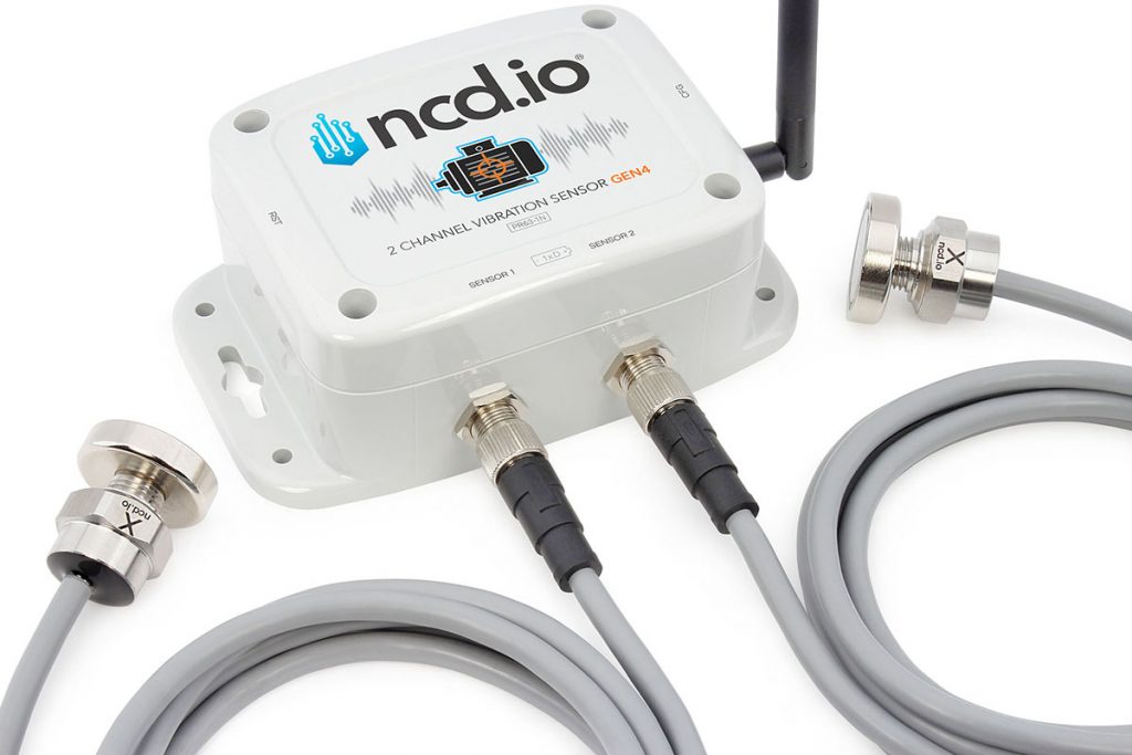
This Article covers the best practices for affixing all Gen4 All-in-One Vibration Sensors (Standalone, 1-Channel, and 2-Channel). Although the sensor models have varied forms (enclosure), the fundamentals of where and how you attach the vibration probe are universal.
It is important that you choose a point that allows safe data collection.
It must have a good mechanical transmission path to the bearing.
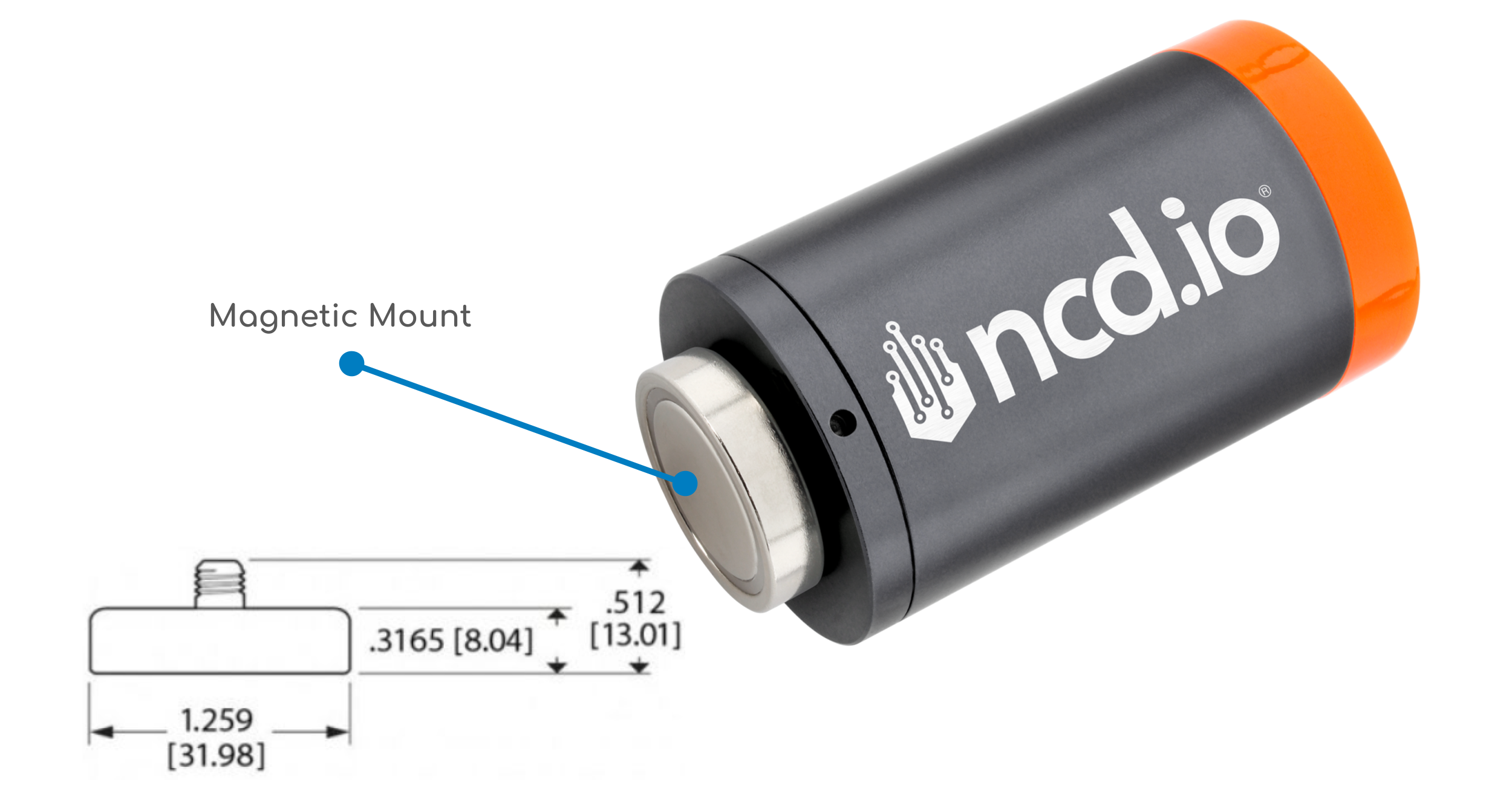
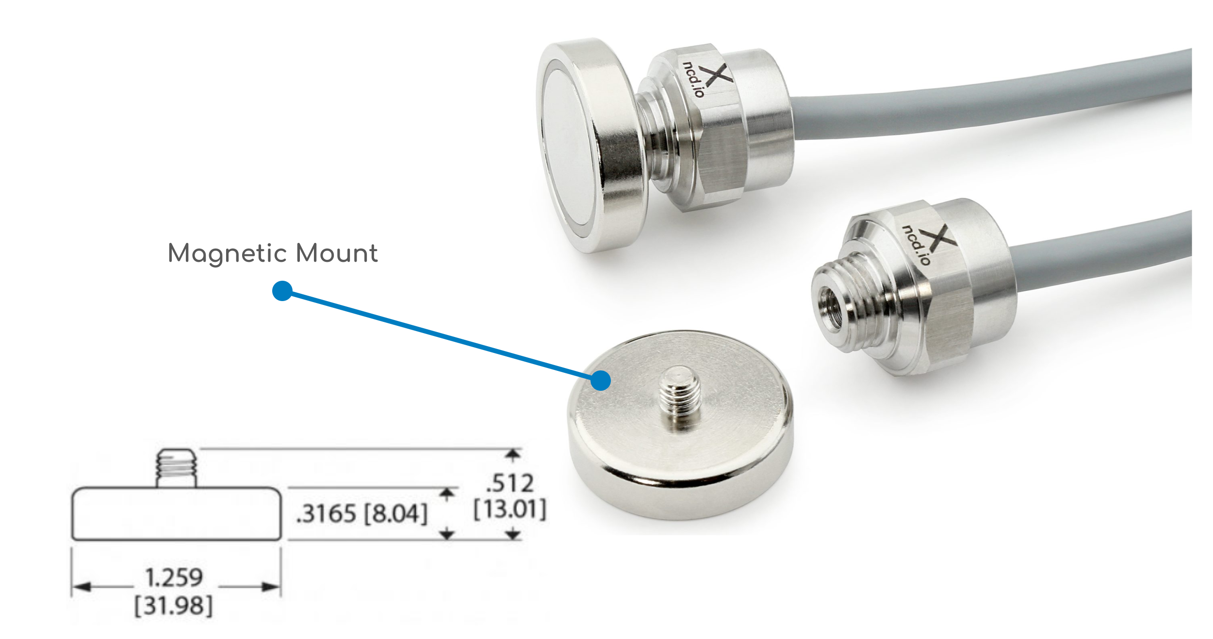
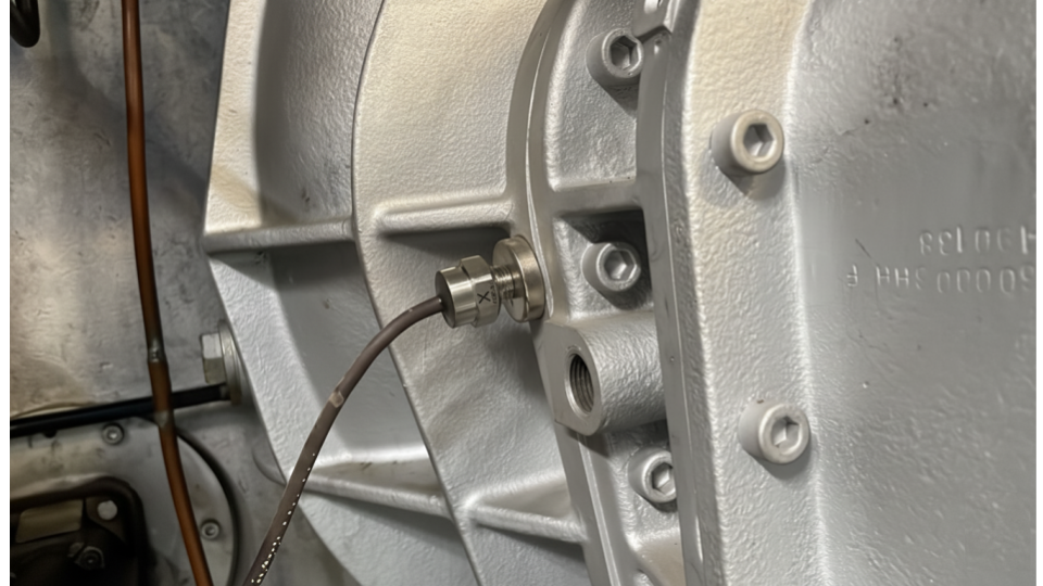
The NCD Vibration Sensor Gen4, in both standalone and external probe versions, comes equipped with a flat magnetic mount.
Where should the sensor be mounted?
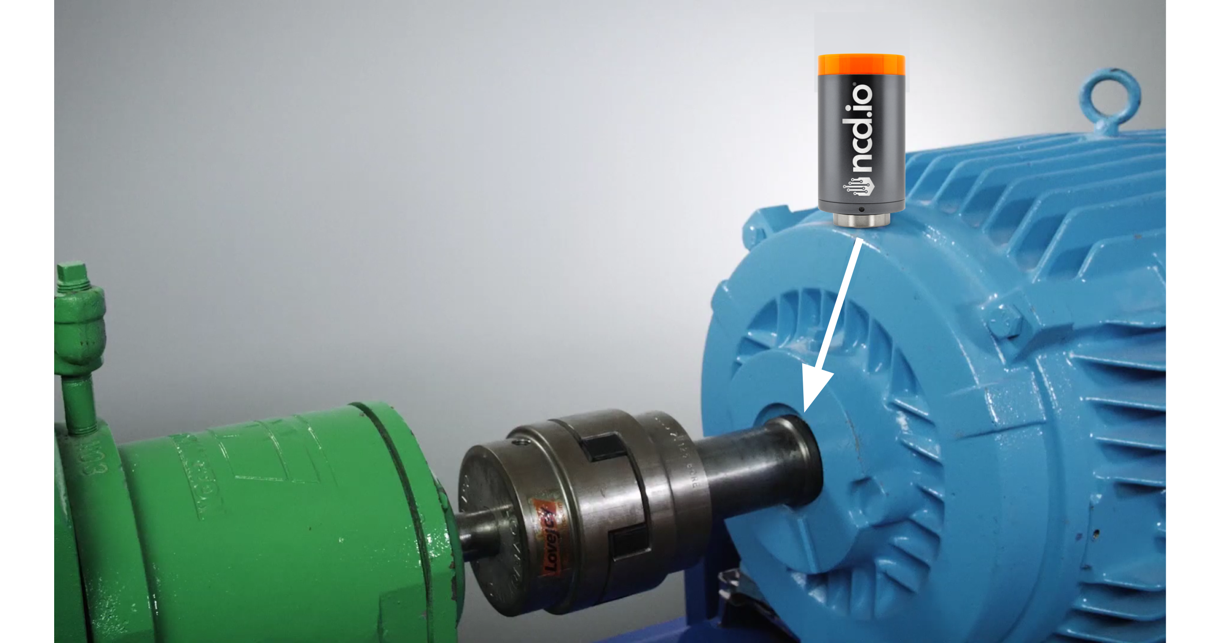
The primary rule is position, the sensor should be positioned as close as feasible to the component you intend to monitor, which is usually a bearing.
The Load Zone
The load zone is the section of the machine, typically the bearing housing, that sustains the rotating shaft. This is where the vibration energy is most concentrated and where defects like bearing wear or imbalance will manifest first.
Where to Attach
Good: A robust, flat area of the bearing housing that is fully cleaned, with all paint and rust removed.
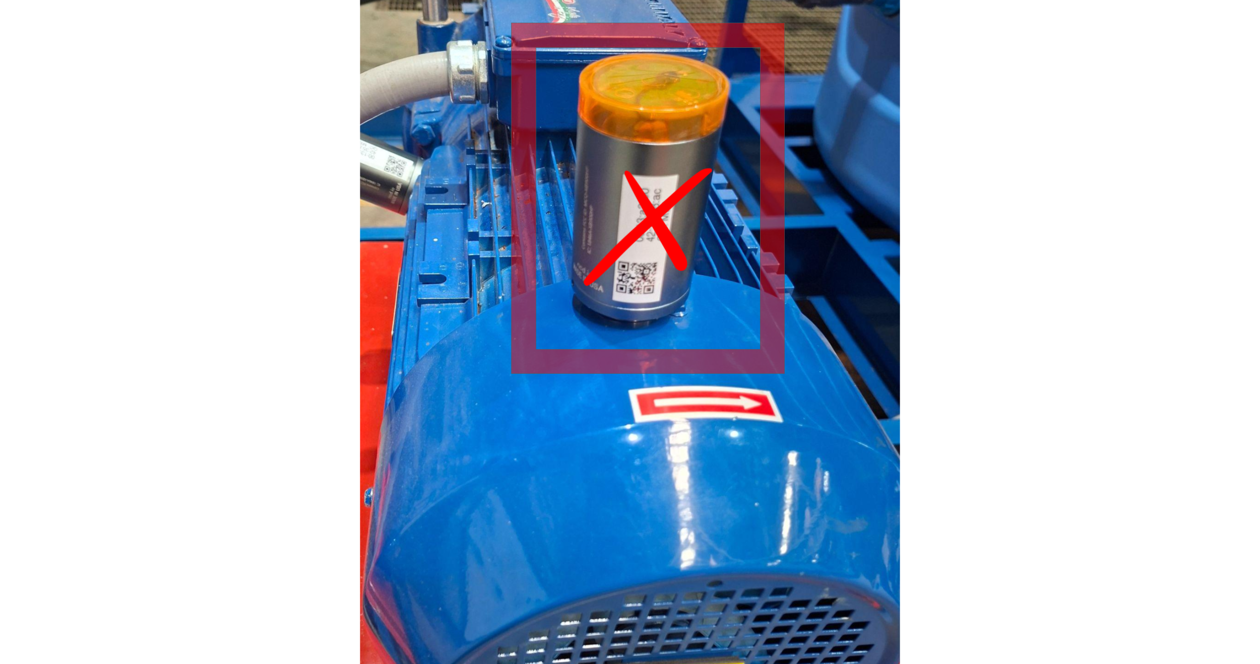
Bad: Thin metal cooling fins, plastic covers, or component enclosures (like a fan shroud). These areas will vibrate at their own frequencies or reduce the true vibration, providing you inaccurate data.
Caution: Never attach a vibration sensor to a fan shroud. The shroud will vibrate separately from the motor’s genuine condition, rendering the data meaningless.
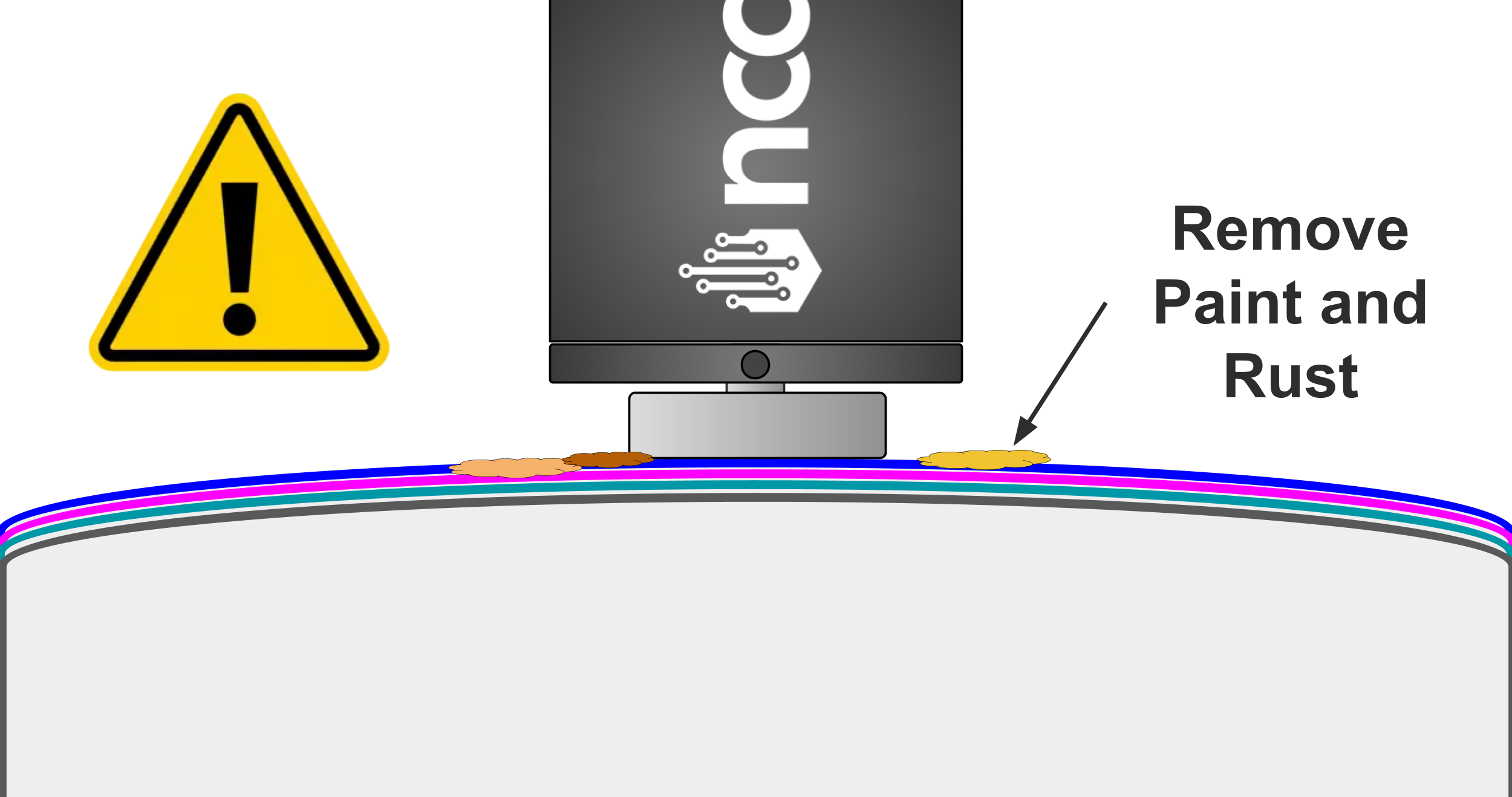
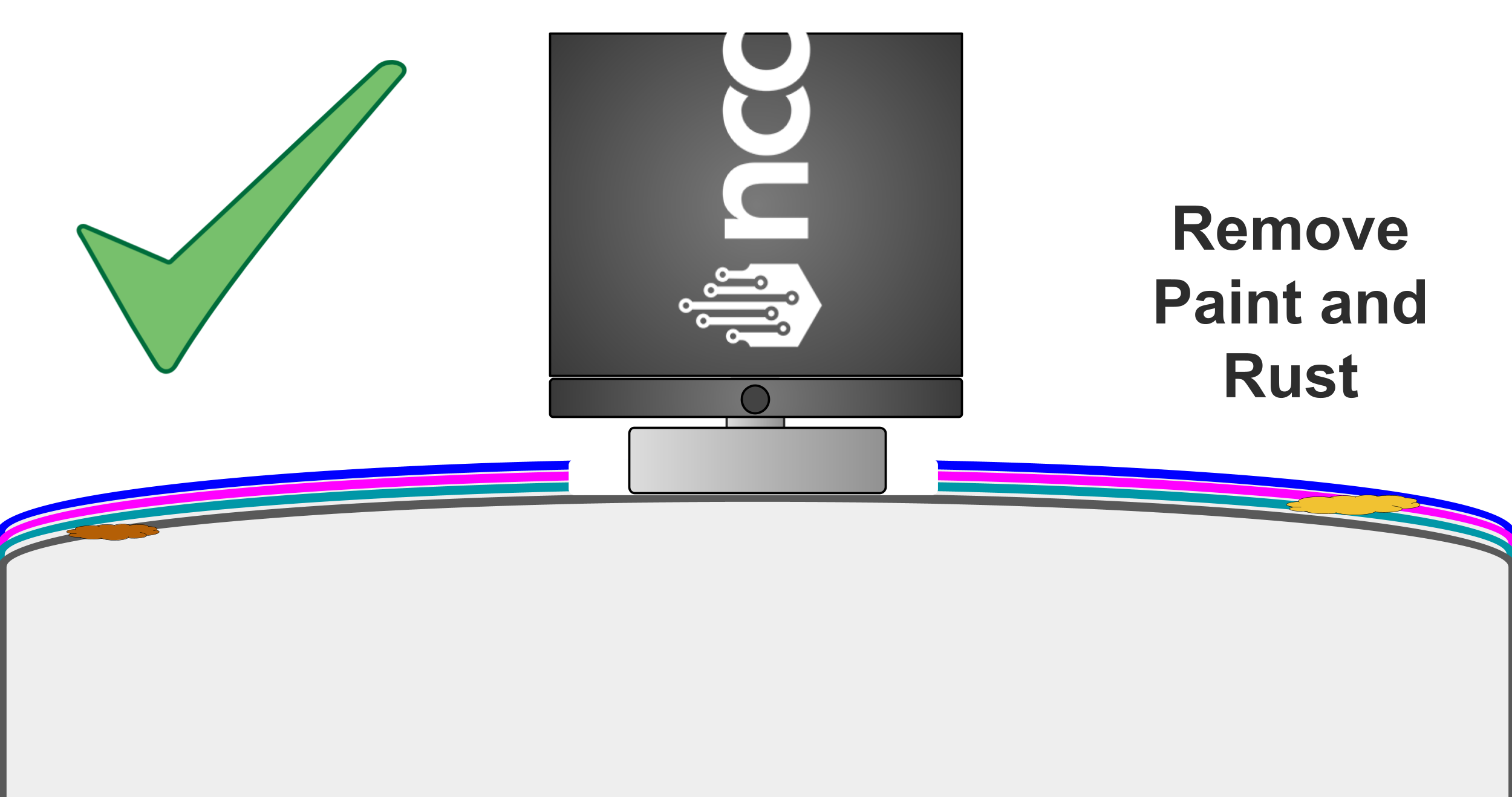
ImportantWe highly recommend a full cleaning and removing all paint and rust from the machine surface where the sensor will be mounted.
Always remember that while the surface may look nicely painted, there could be many layers of paint, and rust may be underneath. If this is the case, the vibration signals from the bearings will reach that surface and essentially be blocked or severely dampened. The signal cannot effectively pass through those layers of paint and rust to reach the sensor.
Mechanical Transmission Path
Everything on a machine vibrates, but many points may rattle, resonate, are not repeatable, and ultimately do not represent the forces occurring at the bearing.
Therefore, there must be a good mechanical transmission path to the bearing. The vibration should only travel along solid metal, with no gaps or joins in the path.
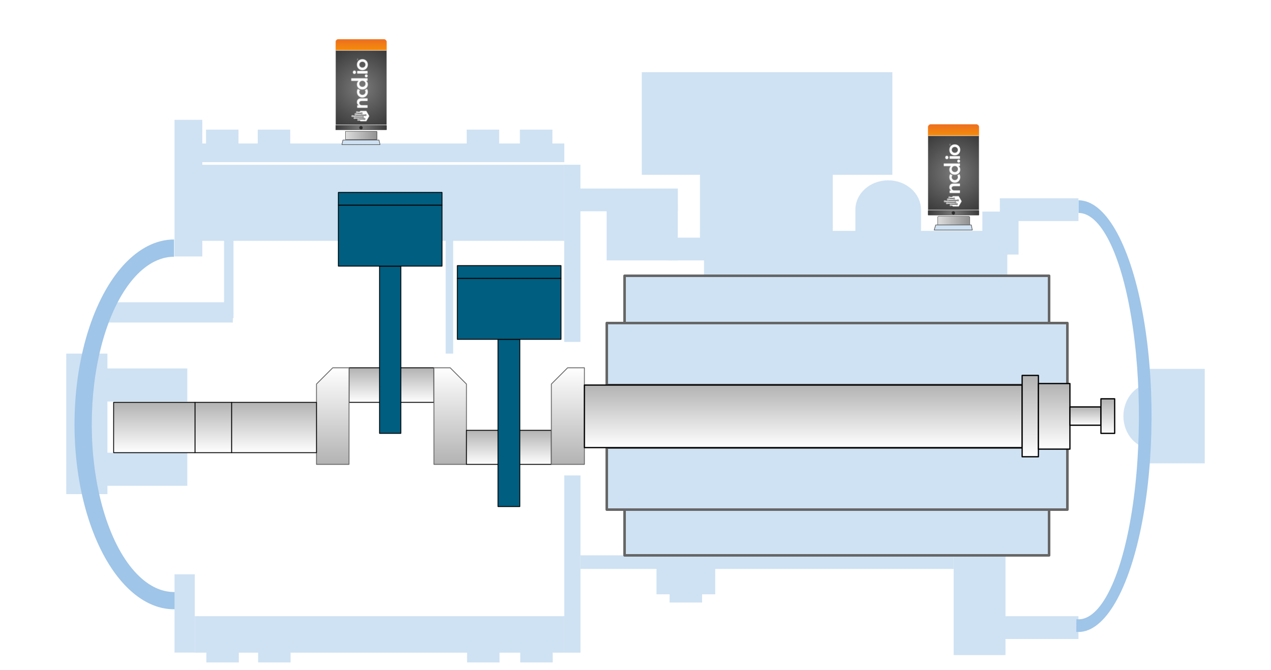
Here are some Practical Mechanical Transmission Path Examples:
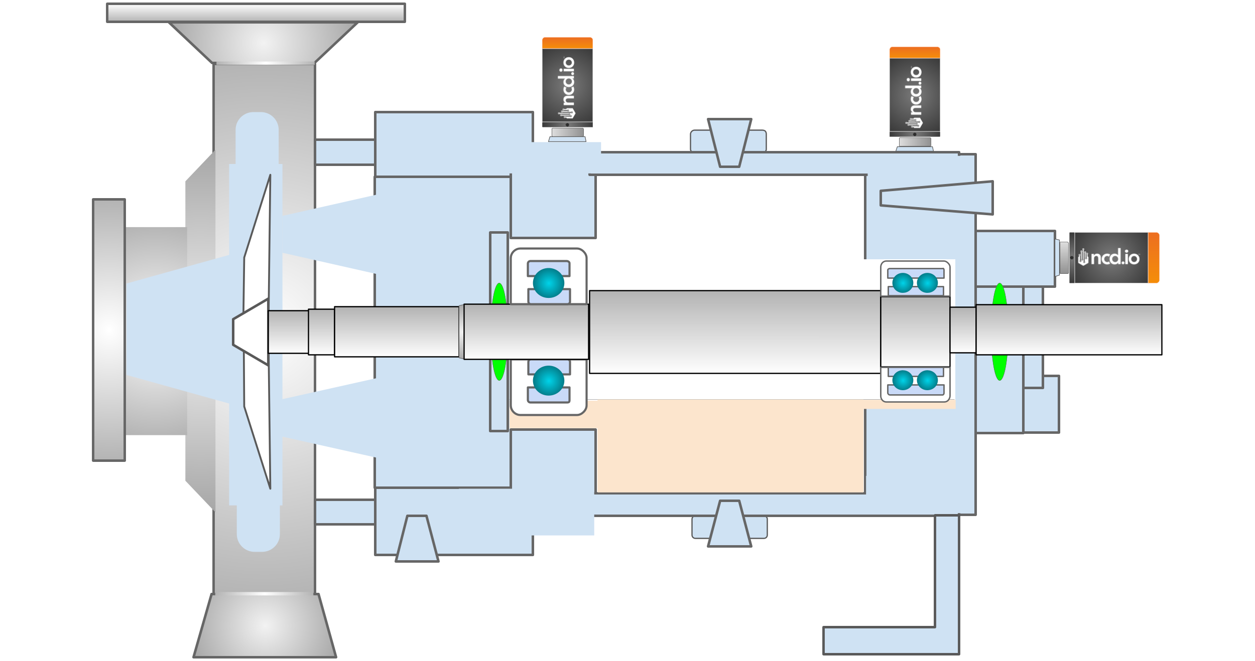
Pump
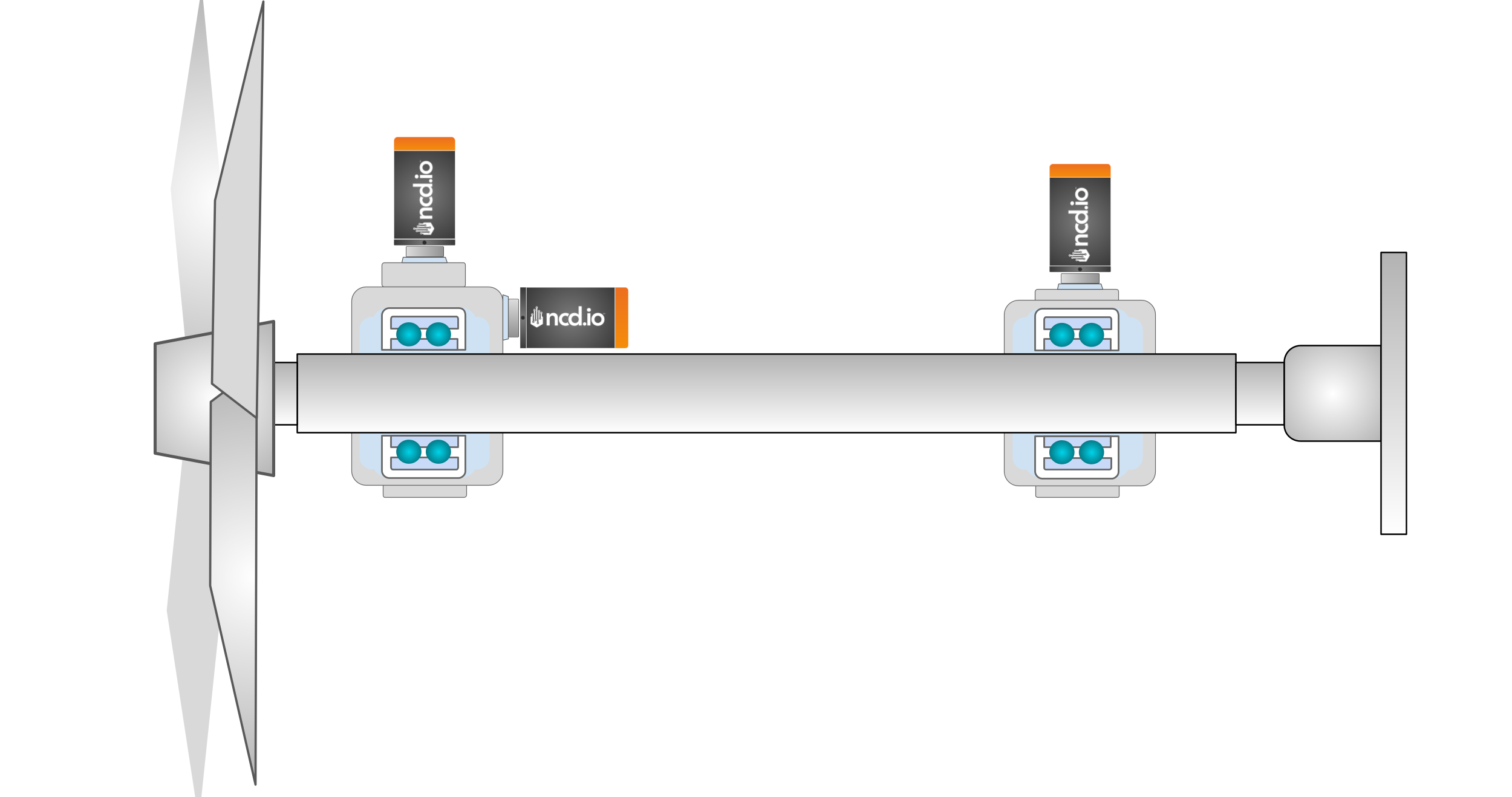
Fan
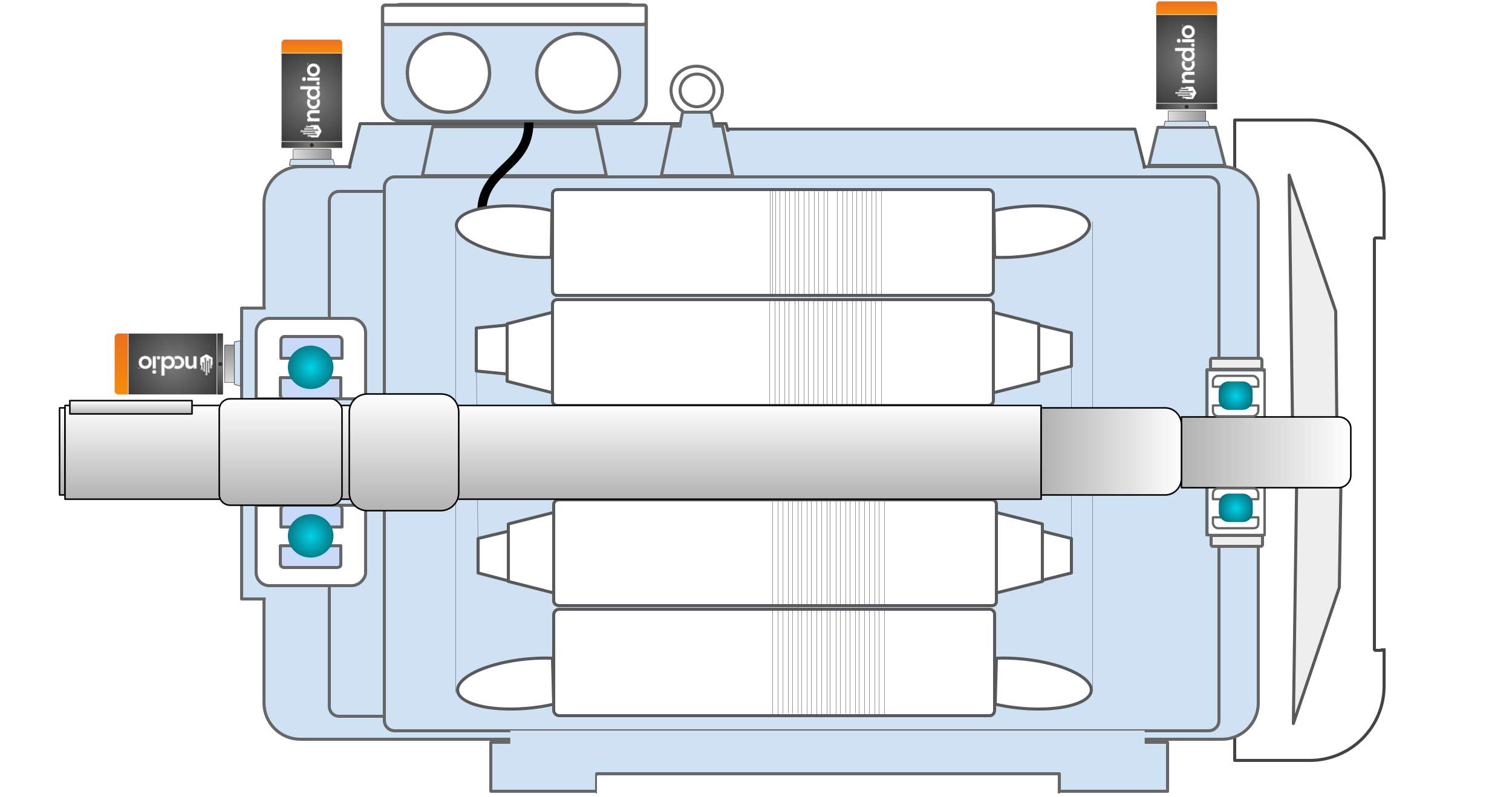
Electric Motor
Semi-Hermetic Compressor
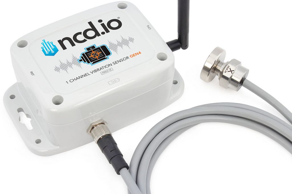
NoteSince the bearing is sometimes located inside an enclosure, it may not be possible to mount the standalone (cylindrical) version of the sensor directly. In these situations, an external probe version can solve the issue: the probe can be installed directly on the bearing enclosure while the electronic and wireless module is mounted externally.
Mounting: How to Affix the Sensor
How a sensor is fastened directly affects the quality and frequency range of the collected data. A loose or incorrect mount will filter out the high-frequency vibrations that are often the first indicators of a bearing defect. It is therefore essential that the sensor is mounted correctly, otherwise the data collected will not be useful.
We must take a measurement that accurately represents the condition of the machine, which allows us to detect faults such as unbalance, bearing defects, and many others. If we are not careful, the sensor data we obtain will not provide the necessary information and will be a waste of time.
The sensor must directly contact the machine surface. The connection must be as strong and stiff as possible, and the surface must be smooth and flat.
There are a number of mounting options available:
Flat Magnet
Two-pole Magnet
Stud Mount
Epoxy
Preferred Method: Stud or Epoxy Mount
This is the permanent and most dependable technique.
Why it’s better: A solid, unyielding connection (like a threaded stud or a hardened epoxy layer) guarantees the sensor merges with the machine. This permits it to precisely convey the full vibration spectrum, from low-frequency imbalance to high-frequency bearing issues.
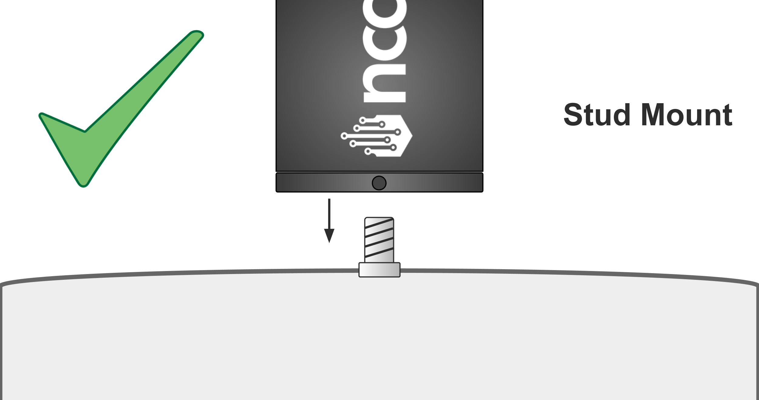
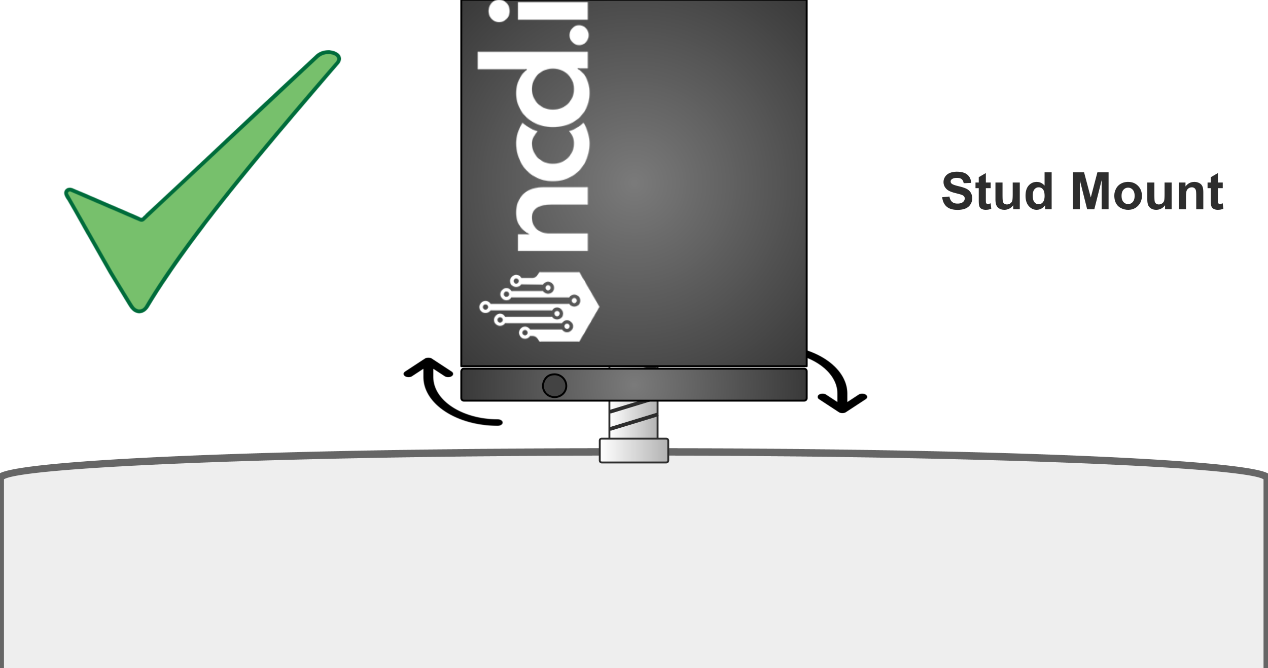
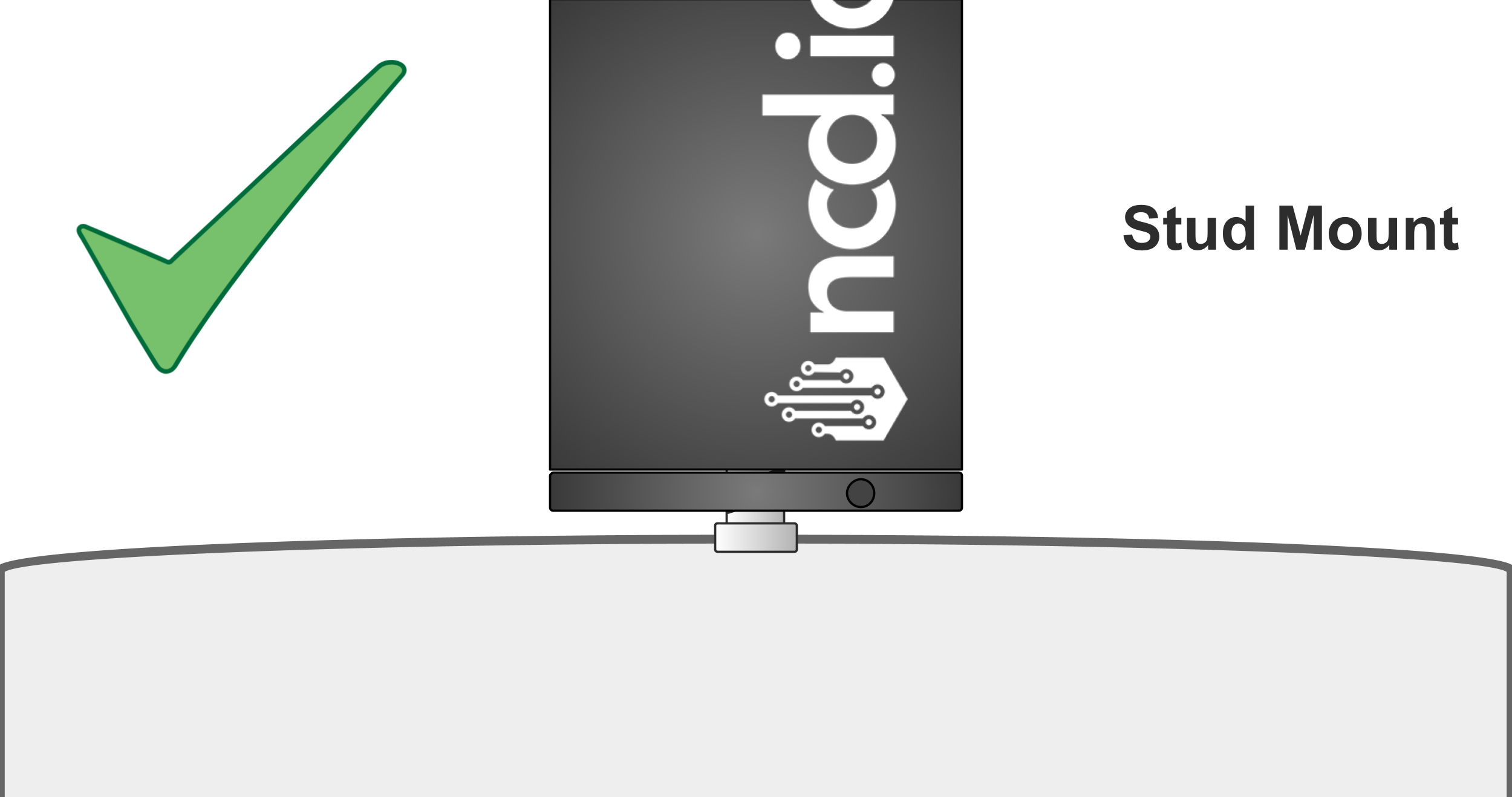
Stud Mount
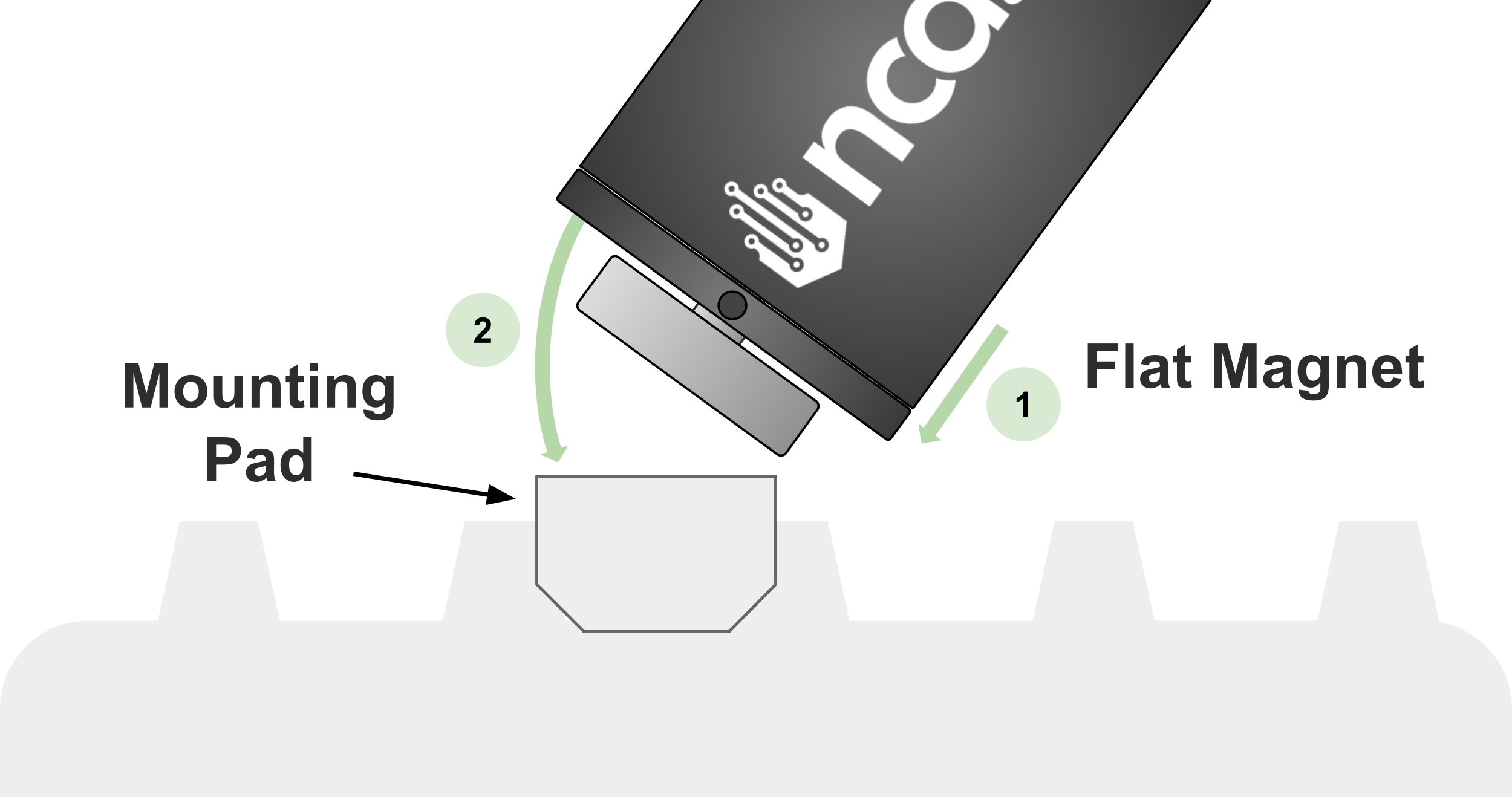
The best option is stud mount, optimum frequency response. A stud mount on an attachment pad is easier to manage (it is not necessary to tap the machine).
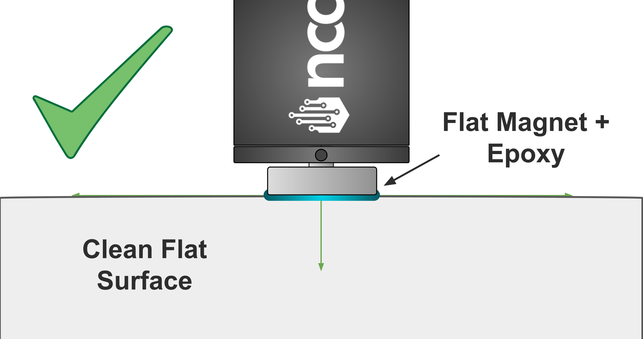
Flat Magnet + Epoxy Mount
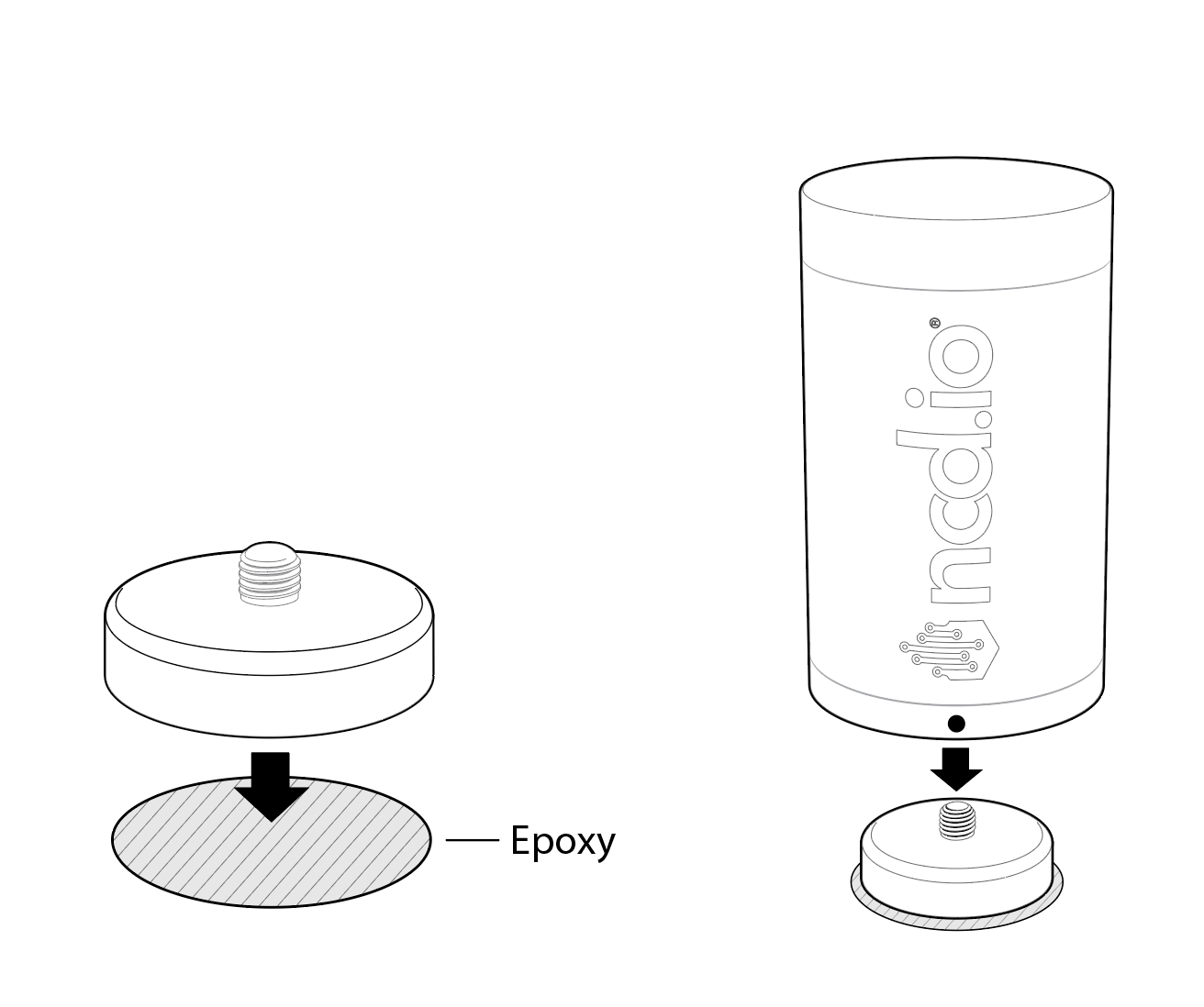
Use a 2-part, hard-curing epoxy. Many users detach the magnetic base, epoxy the base flat onto the machine, and then thread the sensor back onto the now-fixed base.
NoteThe epoxy kit we recommend is the Loctite AA 330.
Note!On curved surfaces we highly recommend to use either a dipole magnet or in special cases flat magnet with epoxy.
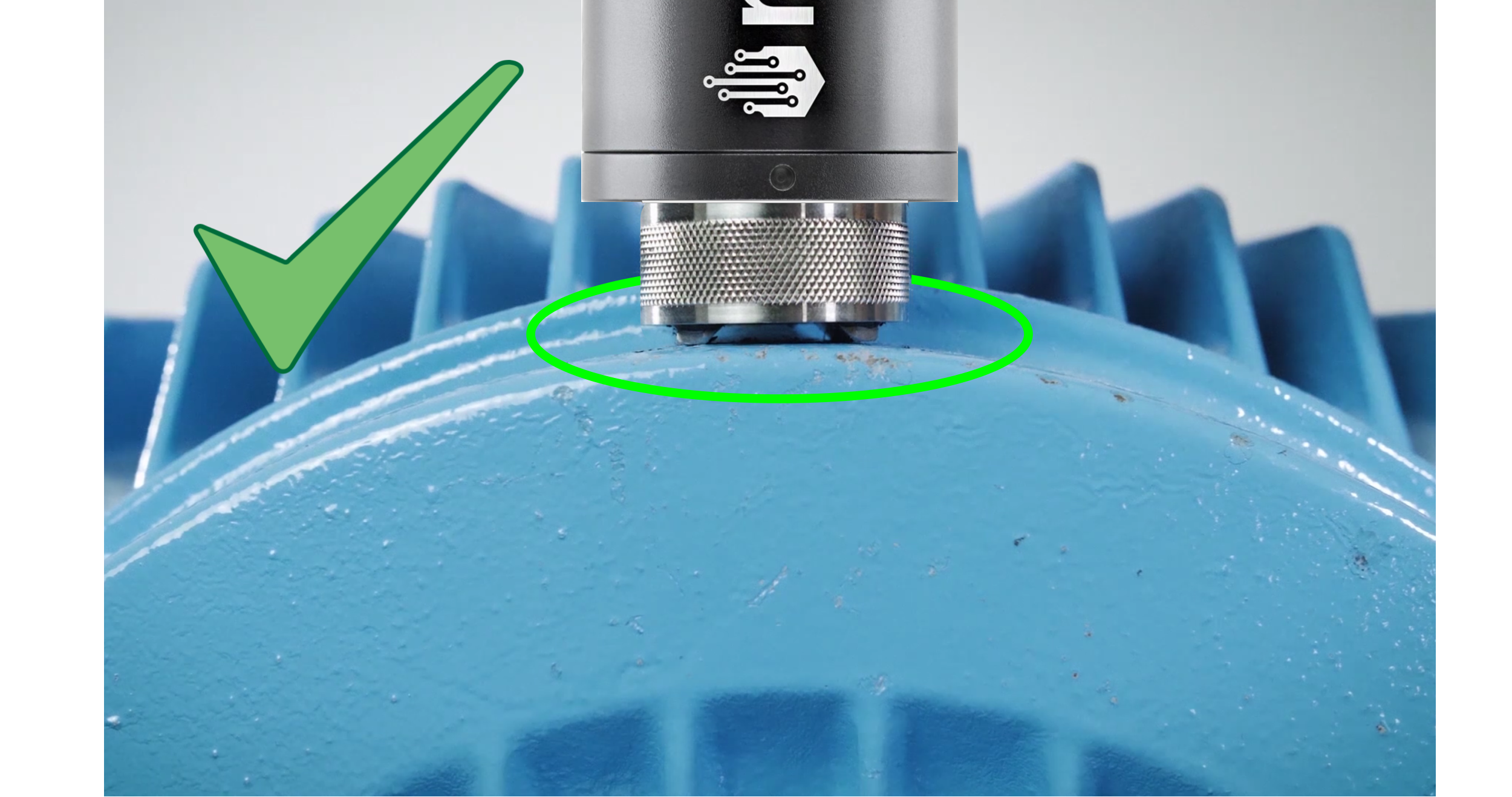
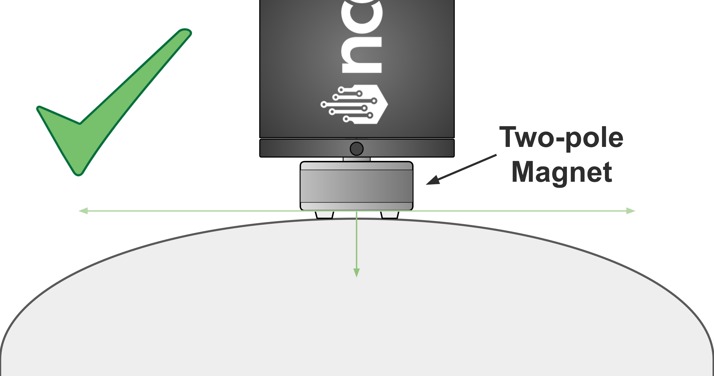
Two-pole Magnetic Mount On Curved Surfaces
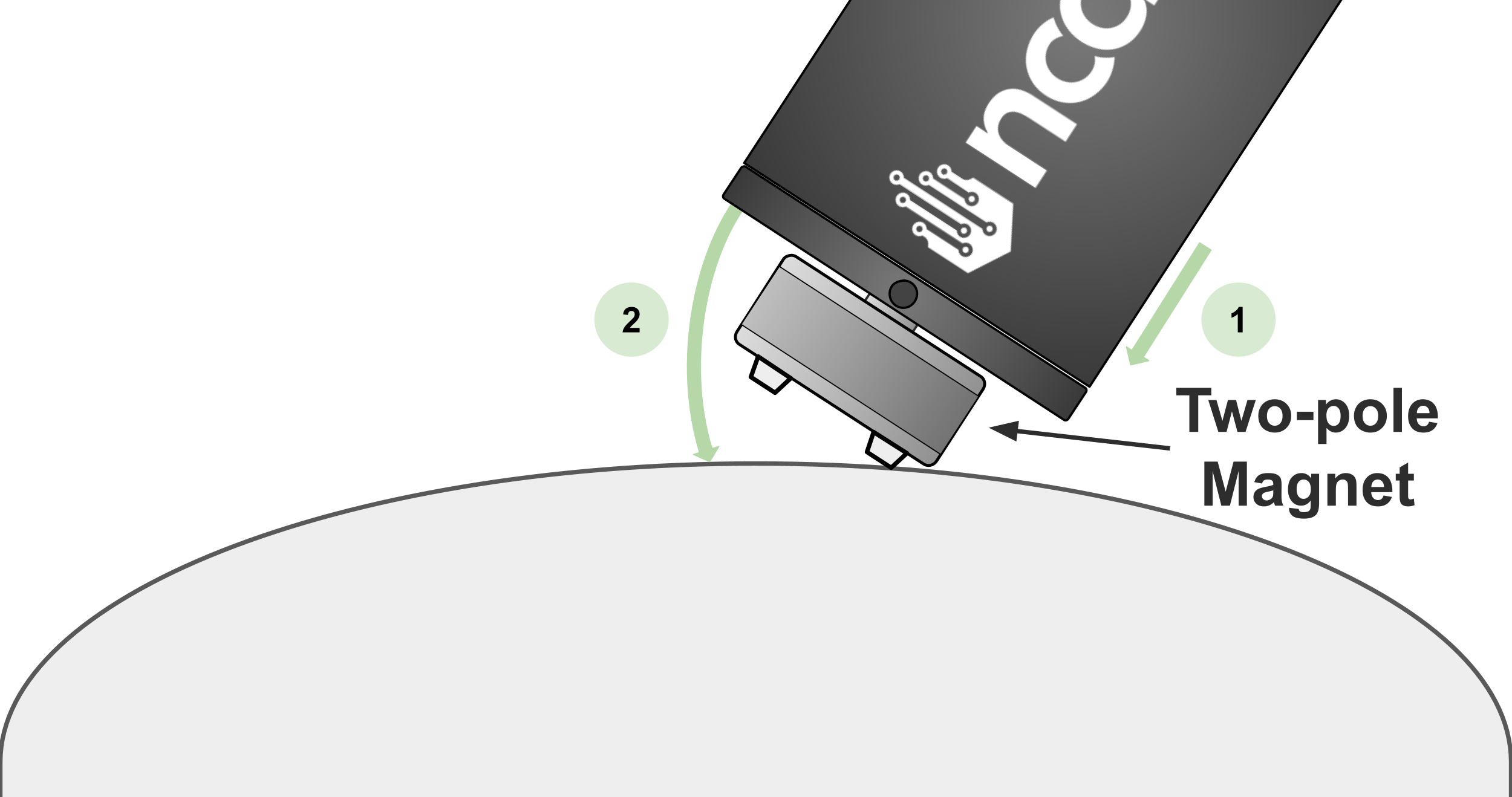
Do not use a flat magnet directly on a curved surface. A two-pole magnet incorporates a two pole (two feet) integral magnet such that it can be placed on a curved surfaces, provided the surface is clean and smooth. Be aware that a two-pole magnet mounted on an unprepared surface will reduce the resulting frequency response.
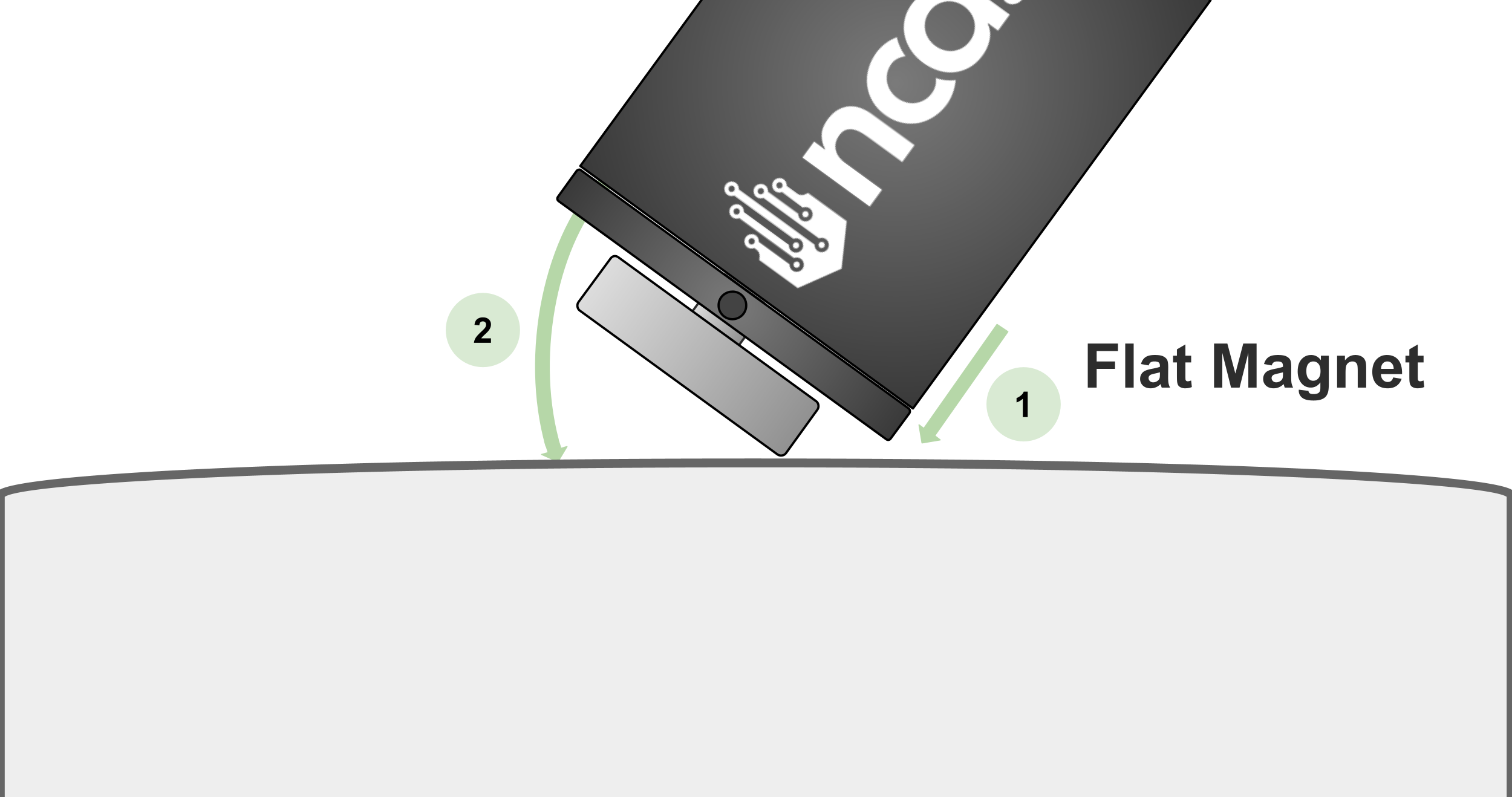
During installation, we highly recommend that you do not ‘thump’ the sensor down onto the surface. You may injure your finger. Instead, lower it onto the side and gently roll it over to make full contact with the surface.
You can purchase a Two-Pole Magnet compatible with NCD Vibration sensors here:
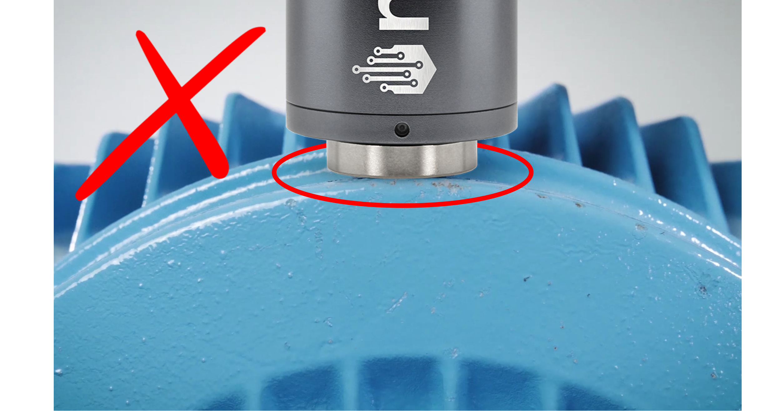
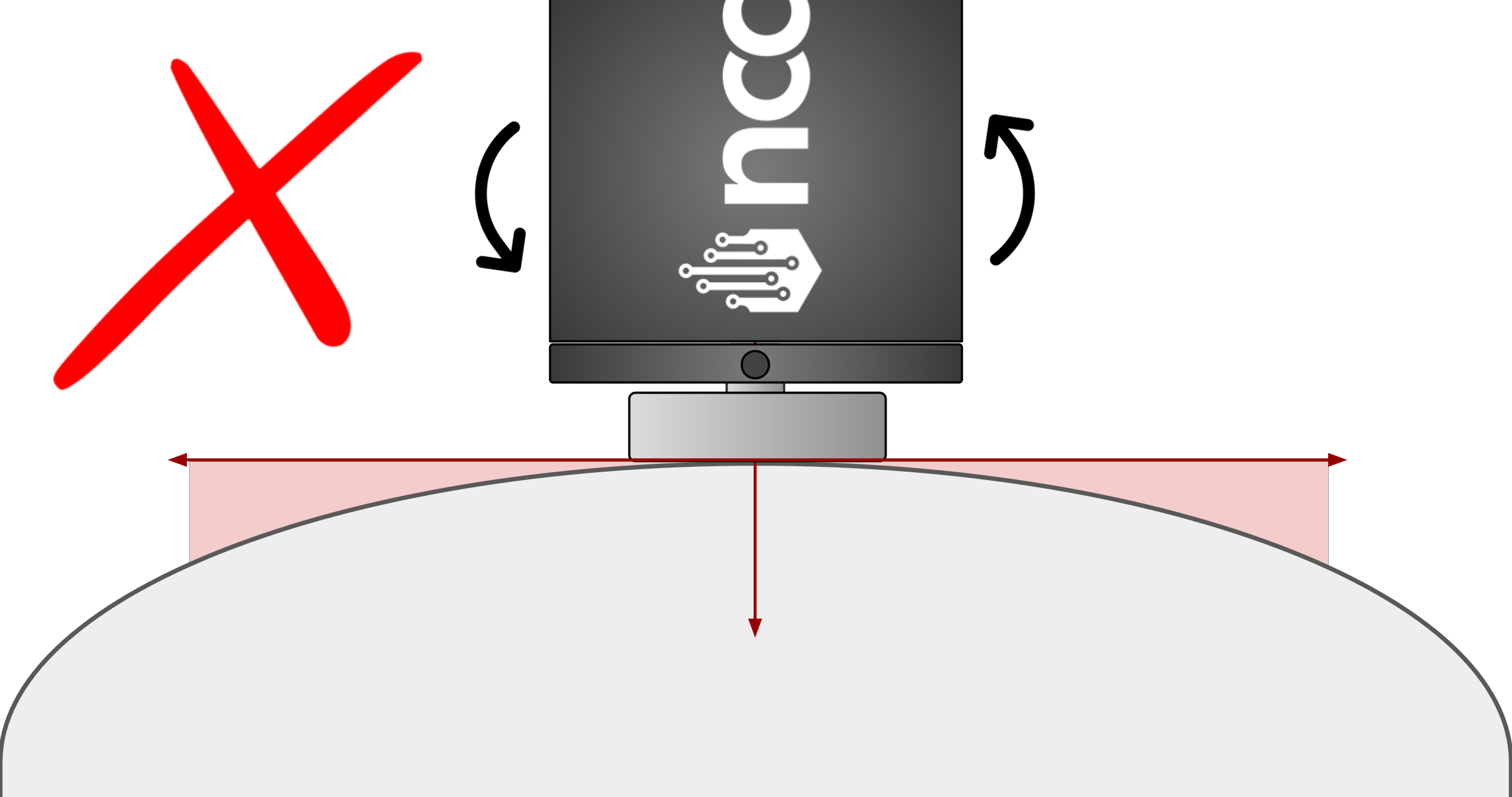
As previously mentioned, it is not recommended to use a flat magnet directly on a curved surface.
This is because when the sensor is placed on a curved surface, gaps will be created between the magnet and the machine surface. This gap could cause the sensor to shift or move during machine operation due to natural vibrations, resulting in the sensor capturing movement that is not related to the actual vibrations emitted by the machine’s internal components.
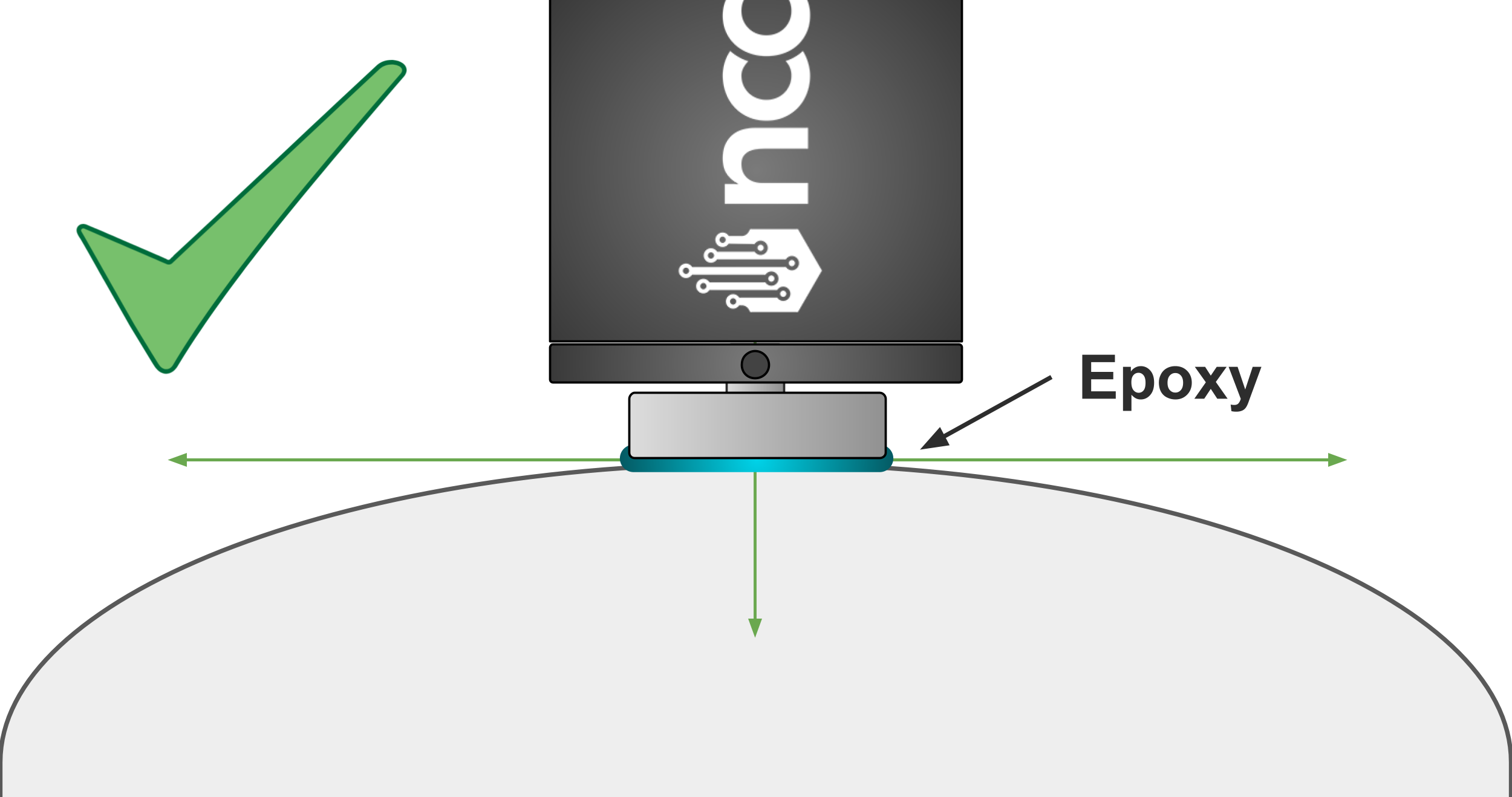
In special cases where a bipolar magnet is unavailable for mounting on curved surfaces, we recommend applying epoxy between the curved surface and the flat magnet to fill the gap, ensuring better contact between the sensor and the machine surface.
For example, you can remove the flat magnet from the sensor, secure the magnet itself to the surface with epoxy, and then screw the sensor back onto the flat magnet as shown in the following image:
Temporary mounting
Flat Magnetic Mount: Magnetic mounts are convenient but are not advised for permanent monitoring.
They can move: A dirty or irregular surface can cause the sensor to “rock” or dislodge, compromising the data.
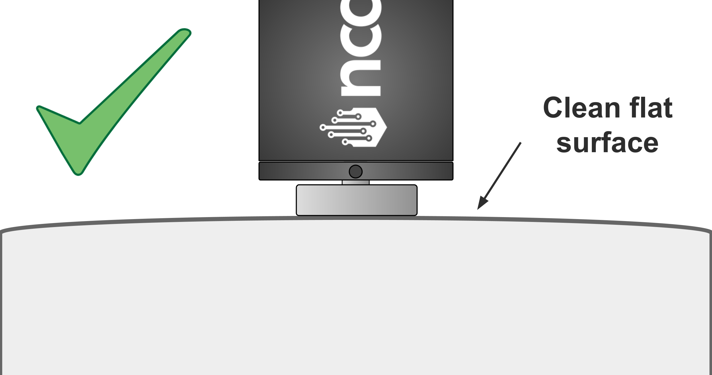
When to use: Employ only on flat surfaces or for brief, temporary checks on a clean, flat, unpainted area.
Flat Magnet
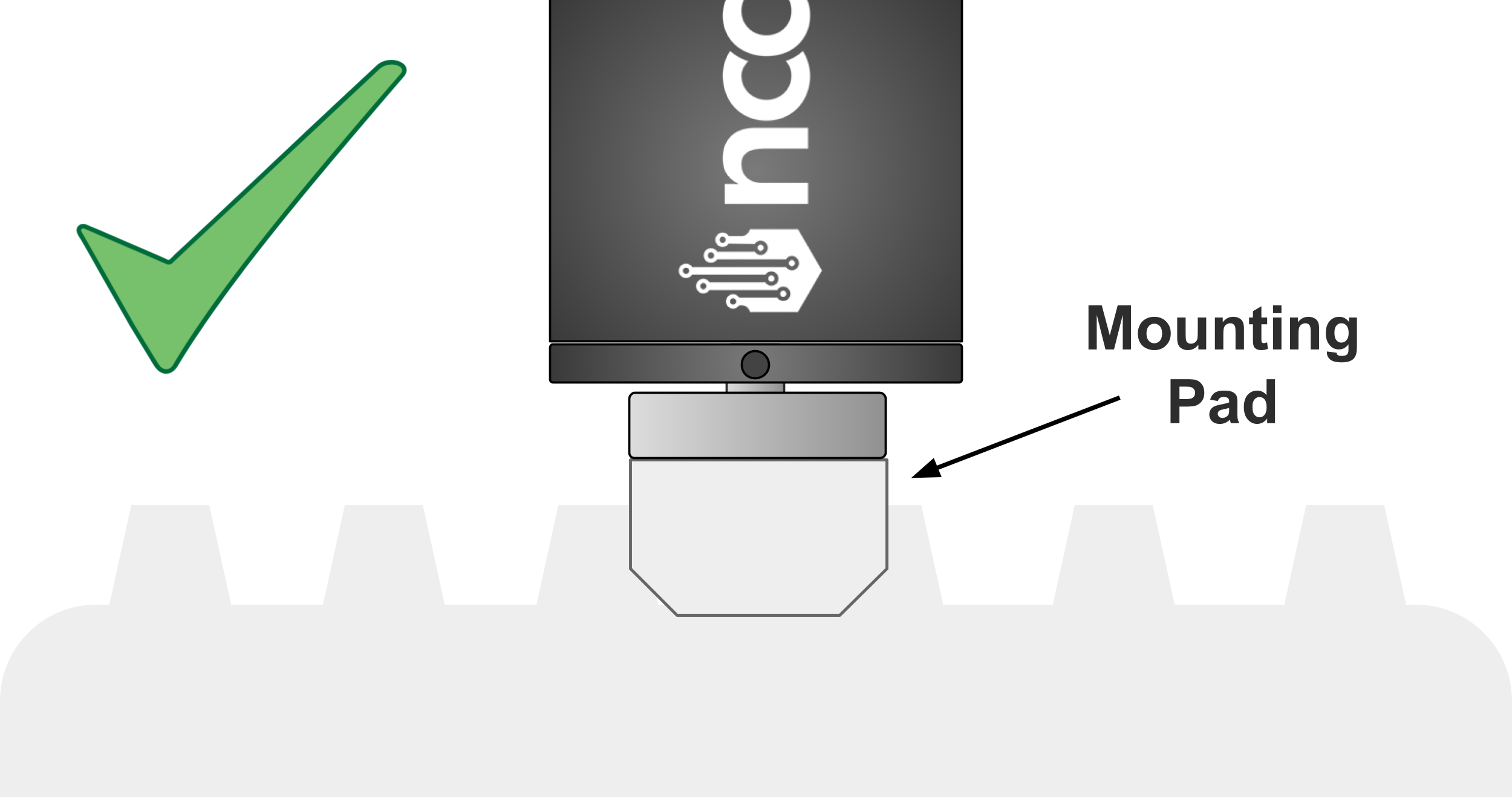
Flat magnets on clean, flat mounting pads have good frequency response. During installation, we highly recommend that you do not ‘thump’ the sensor down onto the surface. You may injure your finger. Instead, lower it onto the side and gently roll it over to make full contact with the surface.
Flat Magnet With Target
When the machine surface is non-smooth or painted, preventing effective direct contact, the Flat Magnet with Target Mounting method offers a highly reliable temporary solution. This technique involves first securing a small, smooth, flat metal target mounting piece directly onto the machine’s surface using either epoxy or by soldering. Once the target is fully secured and cured, the vibration sensor (which includes the flat magnet) can be placed directly onto this prepared target. This ensures a clean, stiff, and repeatable mechanical path for the vibration signal, overcoming surface imperfections to maximize data quality.
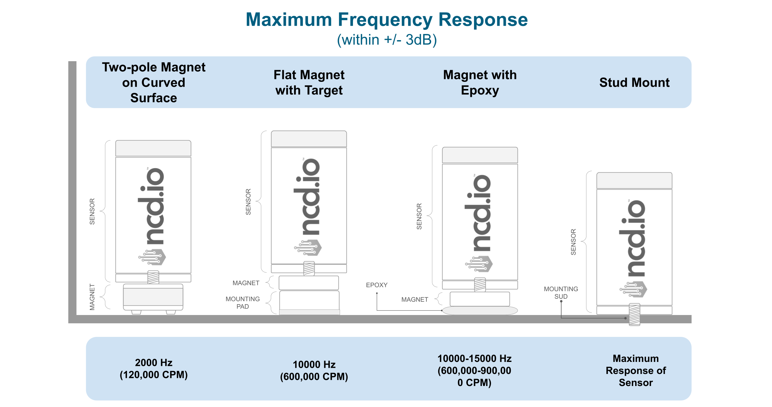
Max Frequency Response
The following table is a comparison of the different recommended mounting modes and their respective Maximum Frequency Response values. This table provides you with an overview of the data quality you can expect, which is directly related to the mounting type used.
Orientation: Repeatability is Key
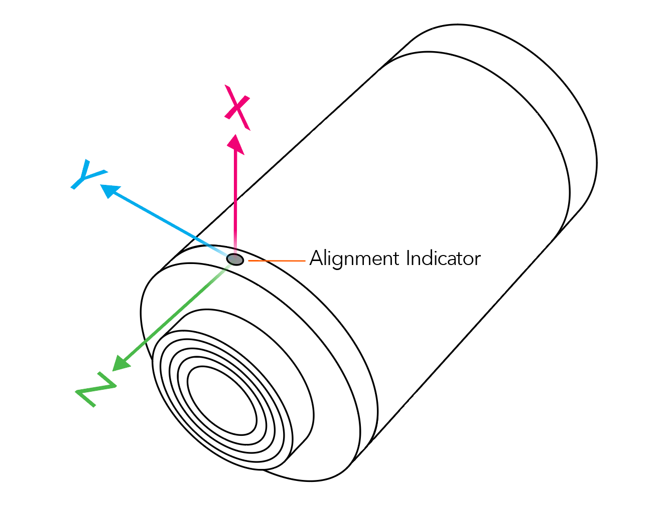
The Gen4 sensor is a tri-axial sensor, which means it captures vibration in three directions (X, Y, and Z) simultaneously. This capability is powerful, but only if you know which direction is which. A vibration signature indicating misalignment looks very different from one indicating imbalance, and the direction of the vibration is the vital clue.
If your sensor is facing a different way each time you take a reading, your X-axis data from today could effectively be your Y-axis data from last month, making reliable trend analysis unachievable.
Here is a picture reference for identifying the X, Y, and Z axes for both sensor versions:
For best practice we recommend to select an orientation, for instance, always align the “X” axis (indicated on the sensor or probe) with the drive shaft of the motor. Be consistent: Ensure that every sensor monitoring a comparable machine (e.g., all your pumps) is positioned in the identical way.
Connect
Seeking next-generation IIoT Smart Vibration Sensors and support? Here are some next steps: