
Choosing between a 4–20 mA current loop and a 0–10 V voltage output is a classic controls decision. Both move an analog value from a sensor or controller to a receiving device, yet they behave very differently in the real world. This guide gives you a practical, decision-ready comparison with simple rules of thumb, a short selector, and field-tested tips.
What each signal actually is?
4–20 mA current loop
A transmitter modulates current from 4 mA (0%) to 20 mA (100%) through a series loop that includes the wiring and the receiver’s input resistor (the “burden”). Because the signal is current, the reading is largely independent of wire resistance. The 4 mA “live zero” lets you detect wire breaks or a dead sensor when the loop current drops toward 0 mA.
0–10 V voltage output
A device sources a voltage between 0 V (0%) and 10 V (100%) referenced to ground. The receiver measures that voltage with a high-impedance input. It is simple and cost-effective, but the value at the receiver can be affected by voltage drops, ground offsets, and electrical noise.
Side-by-side comparison
| Criterion | 4–20 mA Current Loop | 0–10 V Voltage Output |
|---|---|---|
| Signal type | Current (4–20 mA) | Voltage (0–10 V) |
| Noise immunity | High. Less affected by EMI and ground shifts | Moderate. More susceptible to noise/ground loops |
| Typical cable length | Excellent for long runs (hundreds of meters+) | Best for short–moderate runs |
| Fault detection | Built in via “live zero” (4 mA) | Needs extra logic (0 V may be valid or a fault) |
| Powering the transmitter | Two-wire loop power is common | Usually three-wire or separate power |
| Load dependency | Reading independent of wire R (within compliance) | Reading can sag with source impedance and wiring |
| Intrinsically safe | Simple barriers/isolators available | Possible but less standard in process |
| Cost & simplicity | Slightly higher hardware cost; very robust | Often cheaper I/O cards and sensors |
| Common domains | Industrial process, heavy EMI, long runs | HVAC, lighting control, BAS |
| Multi-drop | One analog device per loop (HART overlay possible) | Not intended for analog multi-drop |
Why 4–20 mA often wins in industry
It shrugs off distance and noise. Because the receiver measures current, not voltage, added wire resistance has little effect as long as the loop has enough compliance voltage (supply headroom).
Live zero gives you diagnostics. A broken wire or dead sensor collapses the loop current toward 0 mA, which the controller can alarm on. With 0–10 V, 0 V might be a legitimate measurement.
Simple intrinsic safety. For hazardous areas, 4–20 mA loops pair cleanly with Zener or galvanic barriers.
Two-wire convenience. Loop-powered transmitters can operate from the same two conductors that carry the signal, useful in remote locations.
When 0–10 V is the right call
Short, clean runs. In equipment racks, panels, or building floors with short cables and proper shielding, 0–10 V is inexpensive and easy.
HVAC and lighting ecosystems. Many VFDs, damper actuators, and LED drivers expect 0–10 V control. Integration is plug-and-play.
Plenty of available voltage I/O. Many low-cost PLC and BMS input cards default to 0–10 V and cost less per channel than current inputs.
Practical examples
Example 1: Long run to a remote pressure transmitter
Goal
Measure pipeline pressure at a remote pad, avoid long analog runs, and get clean data into your platform of choice.
Sensor: WIKA A-10 pressure transmitter
The WIKA A-10 is a general-purpose industrial pressure transmitter available in many ranges (from a few psi/bar up to very high pressure) with 0–10 V, 3-wire output. Typical non-linearity 0.25% or 0.5% BFSL; supply 8–30 VDC. Common process connections (¼ NPT, G¼A) and connectors (DIN, M12, cable). You order the full-scale (FS) range you need, and the output is 0–10 V linearly proportional to that FS.
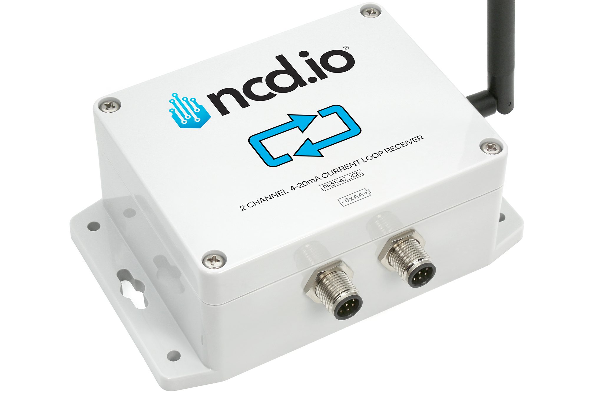
Receiver/bridge: NCD 2-Channel Industrial IoT Long-Range Wireless 0–10 VDC Receiver
This NCD 0-10V receiver is a two-channel 0–10 V receiver with 15-bit ADC, on-board 16 V buck-boost supply to power external 0–10 V sensors, and long-range DigiMesh® radio (~2 mile LOS; farther with high-gain antennas). Runs on 6×AA (up to ~500k transmissions) or 6–32 VDC external power. The product page also provides a direct formula to convert raw ADC counts to volts.
Setup
Thread the WIKA A-10 into the ¼ NPT/G¼ process port near the pipeline gauge valve. Choose a range that covers your normal operating pressure with some headroom (e.g., 0–10 bar FS for a water line that typically runs 5–7 bar).
Install the NCD 0–10 V receiver within a couple meters of the transmitter. This keeps the 0–10 V cable run short (reduces noise/ground error) and uses the long-range radio to cover the rest.
Wire the 3-wire 0–10 V output.
A-10 +Vs → NCD 16 V sensor supply (built-in). The A-10 needs 8–30 V, so 16 V is in spec.
A-10 OUT → NCD CH1 input (0–10 V).
A-10 GND/COM → NCD GND.
If you have a second pressure point or a reference signal, use CH2.
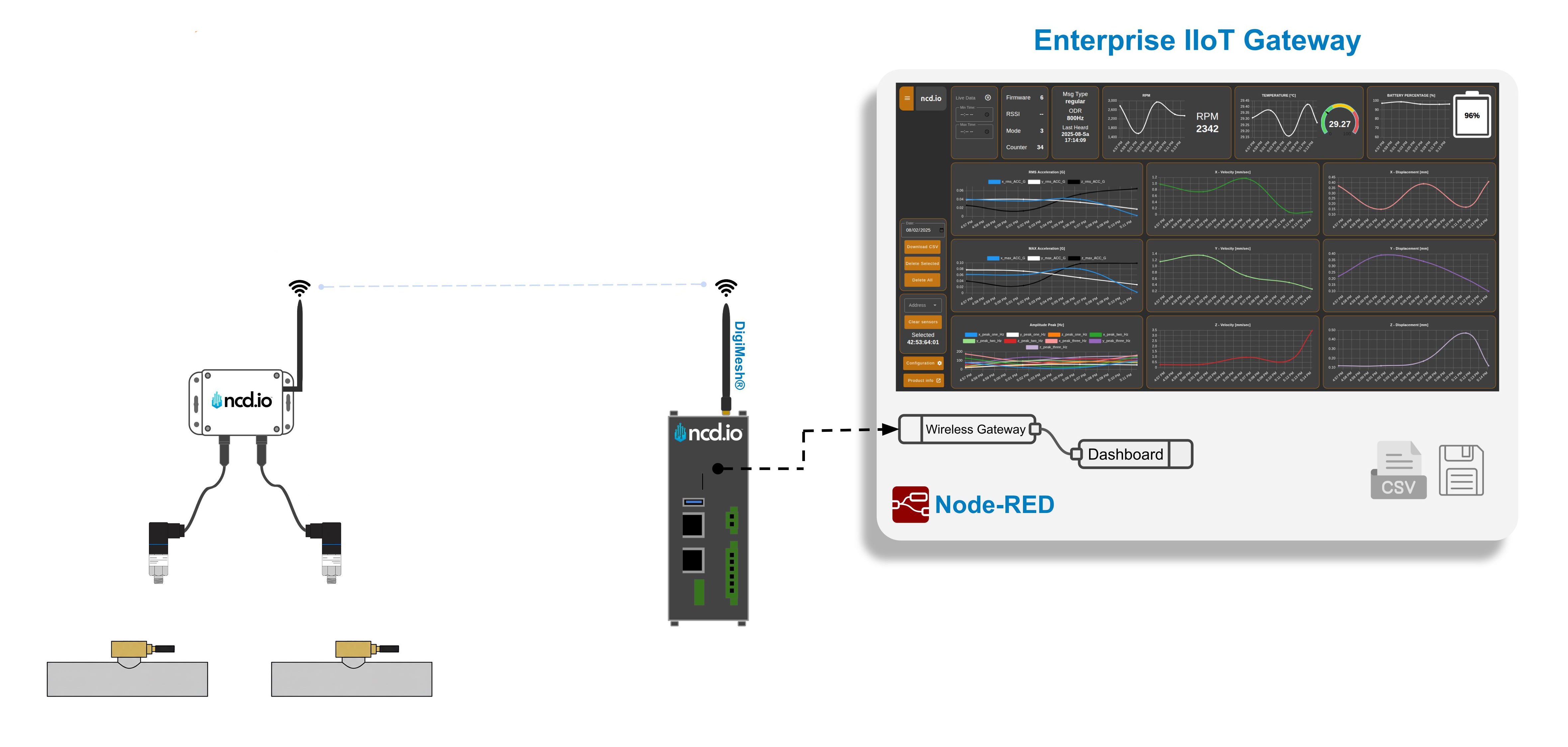
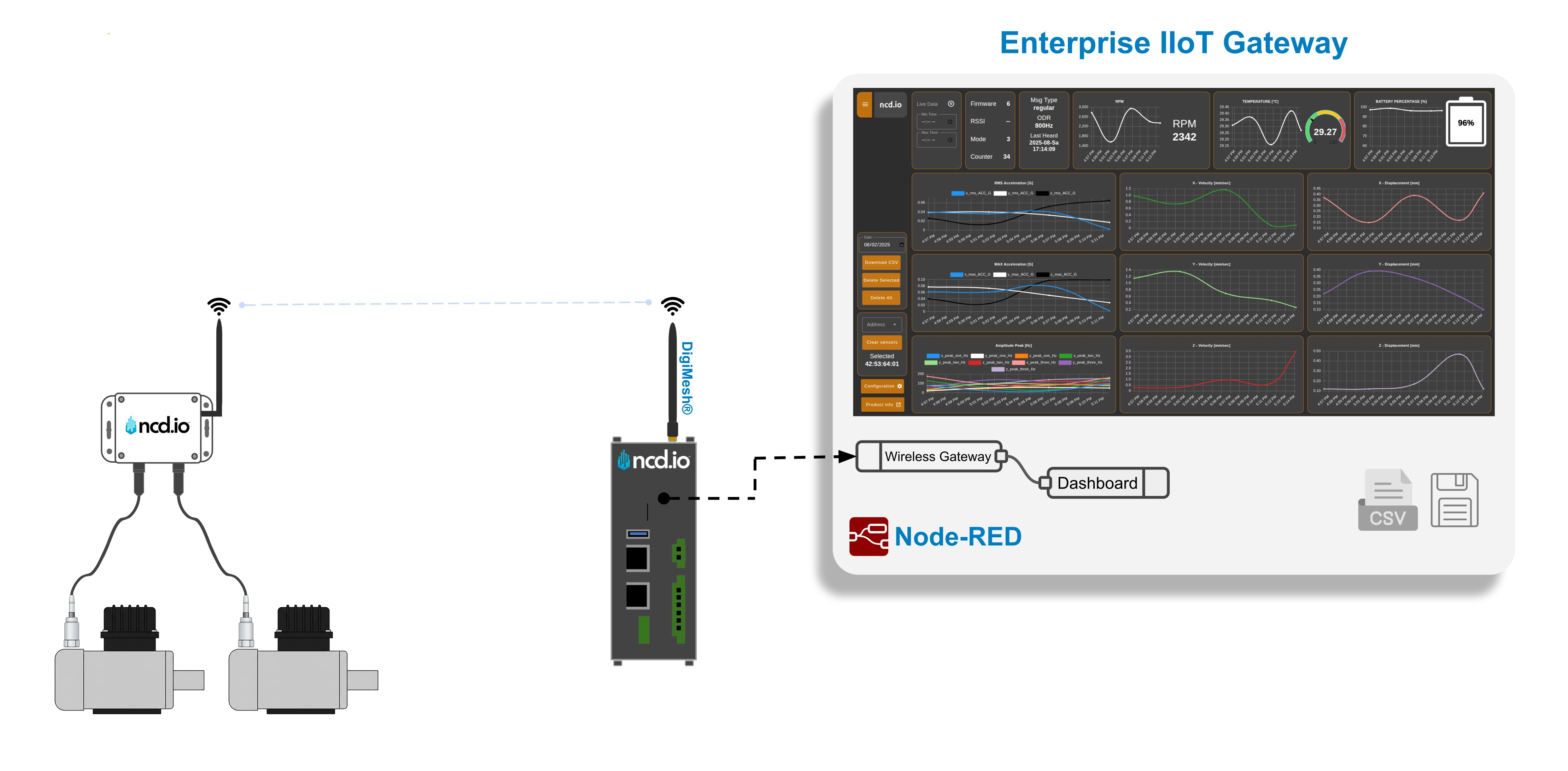
Set the NCD bridge to sample every 5–15 s, with change-based transmit for faster alarms when pressure moves. If the site is cold or has frequent reporting, consider external 12/24 VDC power instead of AA cells. Your data will be automatically transmitted wirelessly to your gateway (you need a DigiMesh enable one like the NCD Atrium IIoT Gateway) for post processing.
Example 2: Vibration monitoring on an industrial pump/motor
Goal
Trend overall vibration (RMS velocity) on a production pump/motor to catch imbalance, looseness, or bearing wear—without running new analog cabling back to a PLC.
Sensor: Hansford Sensors HS-420 Series vibration transmitter
The Hansford HS-420 is an industrial accelerometer with built-in signal conditioning that outputs 4–20 mA proportional to RMS velocity (e.g., 0–25 mm/s = 4–20 mA). Typical frequency response 10–1000 Hz (±5%) to align with ISO 10816, two-wire loop-powered, and available with common mounting threads (¼-28 UNF, M8, etc.). Rated to IP68, –25…+120 °C operation, and base-isolated to reduce ground issues
Receiver (wireless bridge): NCD 2-Channel Long-Range Wireless 4–20 mA Current Receiver
This NCD 4-20mA Current loop receiver is a two-channel 4–20 mA receiver with high-resolution ADC, up to ~2 miles LOS using a long-range mesh radio, and an on-board 16 V buck-boost supply for powering loop sensors. Battery powered (6×AA) with up to ~500k transmissions or 6–32 VDC external power. It utilizes DigiMesh for a robust and long range wireless communication with industrial gateways that are easy to integrate with cloud services like AWS, or process data locally via Node-RED.
This is an easy upgrade path for a 4-20mA sensor, in case you want to eliminate wiring or unify it with any new/existing systems that utilizes DigiMesh wireless sensors.
Setup
Mount the HS-420 on the bearing housing of the pump/motor.
Wire the NCD 4-20ma converter, use one of the available channels to directly connect to the vibration transmitted (simultaneously powering it).
Configure the NCD sensor to your desired specs, for example sampling every 5 seconds and enable change-based transmission for cases where the vibration level are above your desired threshold.
Your system is set up to received data, the sky is the limit on how you will process it.
Bottom line decision criterion
Cable length > 50–100 m or unknown? Prefer 4–20 mA.
High EMI environment (motors, welders, VFDs)? Prefer 4–20 mA.
Built-in fault detection desired? Prefer 4–20 mA.
Short, clean, low-cost install and the device expects 0–10 V? Go 0–10 V.
Hazardous area or intrinsic safety? Prefer 4–20 mA with barriers.
Need to reuse existing building-controls wiring and inputs? Go 0–10 V.
In summary
- Pick 4–20 mA if you have long cable runs, noisy industrial sites, unknown or varying load resistance, or you want easy fault detection with a “live zero.”
- Pick 0–10 V if you have short runs in clean environments, inexpensive controllers with voltage inputs, or building automation gear that already expects 0–10 V