- Device Overview
- Frame Structure
- Example Configuration Commands
- Read Sleep Duration
- Set Sensor Node ID and Sleep Duration
- Read Sensor Network ID
- Set Wireless Sensor Network ID
- Read Sensor Destination Address
- Set Sensor Destination Address
- Set Sensor Destination to Broadcast
- Read Wireless Sensor Transmission Power Level
- Read Wireless Sensor Retries
- Set Wireless Sensor number of Retries
- Set Wireless Sensor Encryption Key
- Troubleshooting
- Appendix
Device Overview
The IoT Wireless Machine Run Time Hour Meter is a device specifically designed to track machine and production run time in industrial settings. It is a flexible device that observes the behavior of the machine it is attached to via its built-in accelerometer and magnetometer,
It has long range wireless capabilities utilizing robust Mesh networking protocols with high level of security and network reliability. It is compact, durable and powered by long lasting batteries.
Features
- Industrial Grade Machine Runtime Monitoring
- Measure Production Runtime
- Measure Number of Cycles
- Acceleration Motion Detection based Runtime calculator
- Magnetic Field Detection based Runtime calculator
- Encrypted Communication with 2 Mile Wireless Range
- Operating Temperature Range -40 to +60 °C
- Humidity Range 0-90%
- Magnet Mounted IP67 Rated Enclosure
- For Indoor and Outdoor Use
- Many Gateway and Modem Options Available
Frame Structure
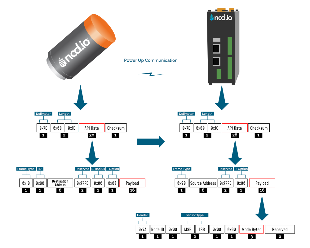
Frame Communication at Power Up
When the device powers up, depending on the mode it is going to work in, it will have a different Power Up Frame
Figure 3 provides an outline of the frame structure at Power Up, where the bytes highlighted in Red denote which mode the device has started in (Run, Configuration or Factory Default). You can look up the corresponding codes in Table 2.
If we further examine the Payload, we can use the Node ID and Sensor Type fields to determine the exact sensor that is sending the data.
A shown in the second column in Table 2, the sensor configures its PAN ID automatically depending upon the mode it is working in. During factory reset it sets the PAN ID to the value given in table therefore the factory reset frame will only be received if your Modem/Gateway PAN ID matches this ID. All 3 types of frames are shown in Figure 3, Figure 4 and Figure 5.
| Mode Type | PAN ID set by Sensor (ASCII) | Frame field | Offset (Payload section) | Value |
|---|---|---|---|---|
| Run | ID save by user / Default | Mode bytes | 7 | 0x52 |
| 8 | 0x55 | |||
| 9 | 0x4E | |||
| Configuration | 7BCD | Mode bytes | 7 | 0x50 |
| 8 | 0x47 | |||
| 9 | 0x4D | |||
| Factory Reset | 7FFF | Mode bytes | 7 | 0x50 |
| 8 | 0x55 | |||
| 9 | 0x4D |
Let us look at the 3 possible power up frames to give an example:
Run Mode Power Up Frame
| Field | Number of bytes | Description |
|---|---|---|
| 7E 00 1E 10 01 00 13 A2 00 42 53 64 53 FF FE 00 00 7A 00 00 00 77 00 00 52 55 4E 00 00 00 00 00 00 06 | Example frame | |
| 0x7E | 1 | Delimiter |
| 0x1001 | 2 | Length |
| 0x10 | 1 | Frame Type (Power Up) |
| 0x0013A20042536453 | 8 | Source Address |
| 0xFFFE | 2 | Reserved |
| 0xC2 | 1 | R. Option |
| 0x7A | 1 | Header with Power Up value |
| 0x00 | 1 | Node ID |
| 0x00 | 1 | Separator |
| 0x0077 | 2 | Sensor Type |
| 0x0000 | 2 | Separator |
| 0x52554E | 3 | Mode Byte for Run Mode |
| 0x000000000000 | 6 | Reserved |
| 0x06 | 1 | Checksum |
Configuration Mode Power Up Frames
| Field | Number of bytes | Description |
|---|---|---|
| 7E 00 1E 10 01 00 13 A2 00 42 53 64 53 FF FE 00 00 7A 00 00 00 77 00 00 50 47 4D 00 00 00 00 00 00 17 | Example frame | |
| 0x7E | 1 | Delimiter |
| 0x001C | 2 | Length |
| 0x90 | 1 | Frame Type |
| 0x0013A20042536453 | 8 | Source Address |
| 0xFFFE | 2 | Reserved |
| 0xC2 | 1 | R. Option |
| 0x7A | 1 | Header |
| 0x00 | 1 | Node ID |
| 0x00 | 1 | Separator |
| 0x0077 | 2 | Sensor Type |
| 0x0000 | 2 | Separator |
| 0x50474D | 3 | Mode Byte for Configuration Mode |
| 0x000000000000 | 6 | Reserved |
| 0x17 | 1 | Checksum |
Factory Reset Mode Power Up Frames (PUM)
| Field | Number of bytes | Description |
|---|---|---|
| 7E 00 1C 90 00 13 A2 00 42 53 64 53 FF FE C2 7A 00 00 00 77 00 00 50 55 4D 00 00 00 00 00 00 D5 | Example frame | |
| 0x7E | 1 | Delimiter |
| 0x001C | 2 | Length |
| 0x90 | 1 | Frame Type |
| 0x0013A20042536453 | 8 | Source Address |
| 0xFFFE | 2 | Reserved |
| 0xC2 | 1 | R. Option |
| 0x7A | 1 | Header |
| 0x00 | 1 | Node ID |
| 0x00 | 1 | Separator |
| 0x0077 | 2 | Sensor Type |
| 0x0000 | 2 | Separator |
| 0x50554D | 3 | Mode Byte for Factory Reset Mode |
| 0x000000000000 | 6 | Reserved |
| 0xD5 | 1 | Checksum |
OTN Mode Frame
| Field | Number of bytes | Description |
|---|---|---|
| 7E 00 1C 90 00 13 A2 00 42 53 64 53 FF FE C2 7A 00 00 00 77 00 00 4F 54 4E 00 00 00 00 00 00 D6 | Example frame | |
| 0x7E | 1 | Delimiter |
| 0x001C | 2 | Length |
| 0x90 | 1 | Frame Type |
| 0x0013A20042536453 | 8 | Source Address |
| 0xFFFE | 2 | Reserved |
| 0xC2 | 1 | R. Option |
| 0x7A | 1 | Header |
| 0x00 | 1 | Node ID |
| 0x00 | 1 | Separator |
| 0x0077 | 2 | Sensor Type |
| 0x0000 | 2 | Separator |
| 0x4F544E | 3 | Mode Byte for OTN Mode |
| 0x000000000000 | 6 | Reserved |
| 0xD6 | 1 | Checksum |
FLY Mode Frame
| Field | Number of bytes | Description |
|---|---|---|
| 7E 00 1C 90 00 13 A2 00 42 53 64 53 FF FE 00 7F 00 0A 00 00 00 00 77 01 46 4C 59 00 00 00 00 01 32 01 01 01 00 00 03 E8 00 00 00 00 00 00 00 00 00 02 58 00 0A 63 01 0A 00 00 00 00 00 00 01 31 | Example frame | |
| 0x7E | 1 | Delimiter |
| 0x001C | 2 | Length |
| 0x90 | 1 | Frame Type |
| 0x0013A20042536453 | 8 | Source Address |
| 0xFFFE | 2 | Reserved |
| 0x00 | 1 | R. Option |
| 0x7F | 1 | Header |
| 0x00 | 1 | Node ID |
| 0x01 | 1 | Firmware Version |
| 0x0000 | 2 | Battery Voltage |
| 0x00 | 1 | Counter |
| 0x0077 | 2 | Sensor Type |
| 0x00 | 1 | Reserved |
| 0x464C59 | 3 | Mode Byte for FLY Mode |
| 0x00 | 1 | Accelerometer Threshold |
| 0x0000 | 2 | Debouncing Timeout |
| 0x00 | 1 | Accelerometer State |
| 0x00000000 | 4 | Counter Threshold |
| 0x00000000 | 4 | Transmit on Change Status |
| 0x0000 | 2 | Shift End 1 |
| 0x0000 | 2 | Shift End 2 |
| 0x0000 | 2 | Shift End 3 |
| 0x0000 | 2 | Shift End 4 |
| 0x0000 | 2 | Reset Timeout |
| 0x00 | 1 | Counter Reset Mode |
| 0x00 | 1 | Sampling Interval |
| 0x00 | 1 | Accelerometer Output Data Rate |
| 0x0000 | 2 | Interrupt Timeout |
| 0x00 | 1 | Accelerometer Enabled Axis |
| 0x000000 | 3 | Hardware ID |
| 0x00000000 | 4 | Report Rate |
| 0x00000000 | 4 | Tx Life Counter |
| 0x00 | 1 | Checksum |
Sensor Data Frame
Run mode is the default mode of operation of this sensor. In this mode, the Machine Runtime sensor sends periodic packets with the sensor measurement data. During the time it is not sending it enters deep-sleep to conserve power. The sensor’s X-bee module operates in API mode and sends packets to the saved destination address on the network specified by the saved PAN ID. Figure 4 illustrates the API transmission/reception procedure.
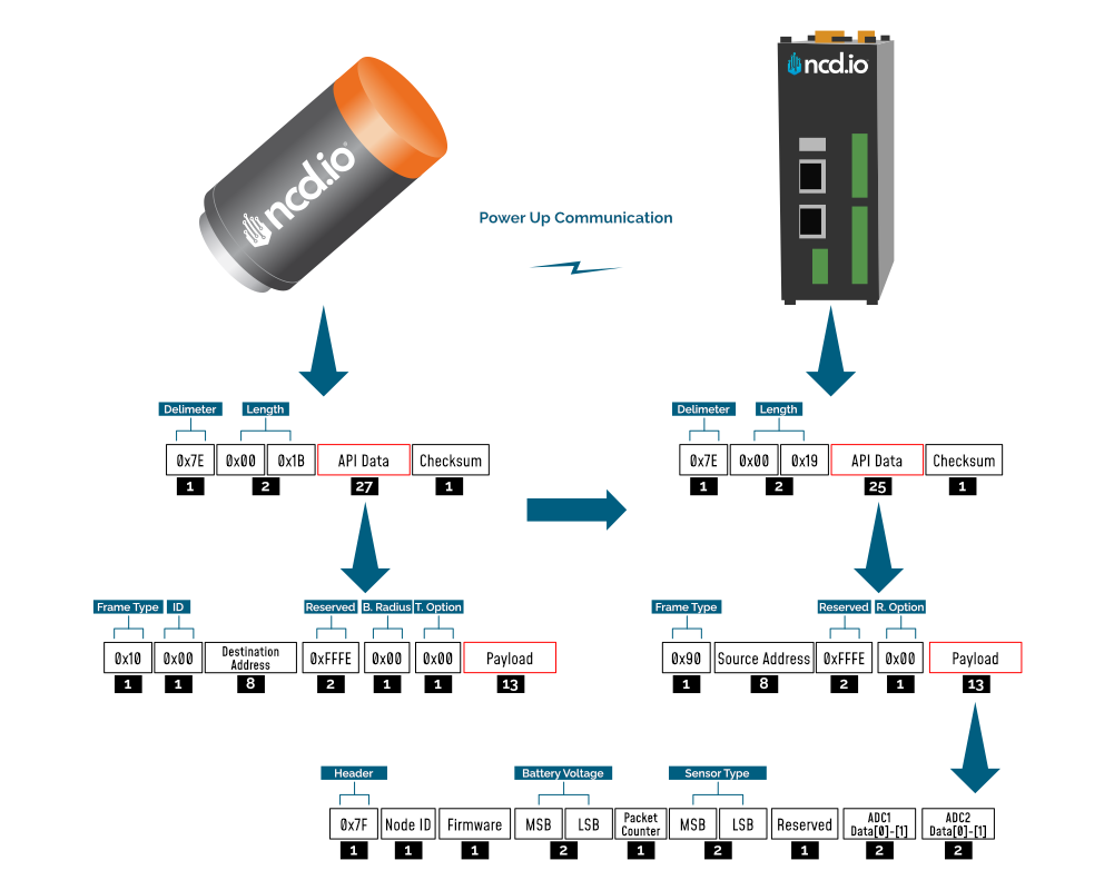
Run Mode Frame with Raw Data Enabled
| Frame Field | Offset (Payload section) | Fixed Value (if any) | Length | Description |
|---|---|---|---|---|
| Header | 0 | 0x7F | 1 | Header to differentiate various types of packets |
| Node ID | 1 | 0x00 | 1 | Node ID to differentiate up to 256 nodes in a network. User configurable values |
| Firmware | 2 | 0x01 | 1 | Used to determine firmware version programmed in the device |
| Battery Voltage | MSB 3 | 0x03 | 2 | Battery Voltage = 0.00322*(03*FF+FE) |
| LSB 4 | 0xFE | Battery Voltage = ((Battery Voltage MSB x 256) + Battery Voltage LSB) x 0.00322 V | ||
| Packet Counter | 5 | - | 1 | It is an 8-bit counter that increments with each packet transmission. It can be used to detect missing packets |
| Sensor Type | MSB 6 | 0x00 | 2 | Two bytes to determine sensor type. It can be used in conjunction with Node ID to create sensor networks of up to 256 nodes for a single type of sensor and multiple such networks can coexist and can be differentiated in processing software on PC end. |
| LSB 7 | 0x77 | Sensor Type 119 | ||
| Error/Reserved byte | 8 | 0x00 | 1 | Bit 2: Validity of Data for sensor: - 0: Data is valid (Accelerometer is present) - 1: Error in accessing sensor Bit 1: Validity of Data for sensor: - 0: Raw data is not included in sensor data - 1: Raw data is included in sensor data |
| Accelerometer Counter | 9/Data[0] | - | 4 | Acc Counter = Data[0] << 24 | Data[1] << 16 | << Data[2] << 8 | Data[3] |
| 10/Data[1] | ||||
| 11/Data[2] | ||||
| 12/Data[3] | ||||
| Accelerometer Uptime | 13/Data[0] | - | 4 | Acc Uptime = Data[0] << 24 | Data[1] << 16 | << Data[2] << 8 | Data[3] |
| 14/Data[1] | ||||
| 15/Data[2] | ||||
| 16/Data[3] | ||||
| Magnetometer Counter | 17/Data[0] | - | 4 | Mag Counterr = Data[0] << 24 | Data[1] << 16 | << Data[2] << 8 | Data[3] |
| 18/Data[1] | ||||
| 19/Data[2] | ||||
| 20/Data[3] | ||||
| Magnetometer Uptime | 21/Data[0] | - | 4 | Mag Uptime = Data[0] << 24 | Data[1] << 16 | << Data[2] << 8 | Data[3] |
| 22/Data[1] | ||||
| 23/Data[2] | ||||
| 24/Data[3] | ||||
| Input Logic State | 25/Data[0] | - | 1 | Bit 1: Logic Status Accelerometer Bit 2: Logic Status Magnetometer |
| Report Type | 26/Data[0] | - | 1 | 0x00 -- Regular 0x01 -- Shift End 0x02 -- Interrrupt 0x03 -- Threshold |
| Real-Time Clock | 27/Data[0] | - | 1 | Data[0] -- Hour Data[1] -- Minute Data[2] -- Second |
| Temperature | 28/Data[0] | - | 2 | Temperature = (Data[0] * FF + Data[1])/100 |
| 29/Data[1] | ||||
| Accelerometer Sample 1 | 30/Data[0] | - | 6 | x data = (Data[0] * FF + Data[1]) / 100 y data = (Data[2] * FF + Data[3]) / 100 z data = (Data[4] * FF + Data[5]) / 100 |
| 31/Data[1] | ||||
| 32/Data[2] | ||||
| 33/Data[3] | ||||
| 34/Data[4] | ||||
| 35/Data[5] | ||||
| Accelerometer Sample 2 | 36/Data[0] | - | 6 | x data = (Data[0] * FF + Data[1]) / 100 y data = (Data[2] * FF + Data[3]) / 100 z data = (Data[4] * FF + Data[5]) / 100 |
| 37/Data[1] | ||||
| 38/Data[2] | ||||
| 39/Data[3] | ||||
| 40/Data[4] | ||||
| 41/Data[5] | ||||
| Accelerometer Sample 3 | 42/Data[0] | - | 6 | x data = (Data[0] * FF + Data[1]) / 100 y data = (Data[2] * FF + Data[3]) / 100 z data = (Data[4] * FF + Data[5]) / 100 |
| 43/Data[1] | ||||
| 44/Data[2] | ||||
| 45/Data[3] | ||||
| 46/Data[4] | ||||
| 47/Data[5] | ||||
| Accelerometer Sample 4 | 48/Data[0] | - | 6 | x data = (Data[0] * FF + Data[1]) / 100 y data = (Data[2] * FF + Data[3]) / 100 z data = (Data[4] * FF + Data[5]) / 100 |
| 49/Data[1] | ||||
| 50/Data[2] | ||||
| 51/Data[3] | ||||
| 52/Data[4] | ||||
| 53/Data[5] | ||||
| Accelerometer Sample 5 | 54/Data[0] | - | 6 | x data = (Data[0] * FF + Data[1]) / 100 y data = (Data[2] * FF + Data[3]) / 100 z data = (Data[4] * FF + Data[5]) / 100 |
| 55/Data[1] | ||||
| 56/Data[2] | ||||
| 57/Data[3] | ||||
| 58/Data[4] | ||||
| 59/Data[5] | ||||
| Accelerometer Sample 6 | 60/Data[0] | - | 6 | x data = (Data[0] * FF + Data[1]) / 100 y data = (Data[2] * FF + Data[3]) / 100 z data = (Data[4] * FF + Data[5]) / 100 |
| 61/Data[1] | ||||
| 62/Data[2] | ||||
| 63/Data[3] | ||||
| 64/Data[4] | ||||
| 65/Data[5] | ||||
| Accelerometer Sample 7 | 66/Data[0] | - | 6 | x data = (Data[0] * FF + Data[1]) / 100 y data = (Data[2] * FF + Data[3]) / 100 z data = (Data[4] * FF + Data[5]) / 100 |
| 67/Data[1] | ||||
| 68/Data[2] | ||||
| 69/Data[3] | ||||
| 70/Data[4] | ||||
| 71/Data[5] | ||||
| Accelerometer Sample 8 | 72/Data[0] | - | 6 | x data = (Data[0] * FF + Data[1]) / 100 y data = (Data[2] * FF + Data[3]) / 100 z data = (Data[4] * FF + Data[5]) / 100 |
| 73/Data[1] | ||||
| 74/Data[2] | ||||
| 75/Data[3] | ||||
| 76/Data[4] | ||||
| 77/Data[5] | ||||
| Accelerometer Sample 9 | 78/Data[0] | - | 6 | x data = (Data[0] * FF + Data[1]) / 100 y data = (Data[2] * FF + Data[3]) / 100 z data = (Data[4] * FF + Data[5]) / 100 |
| 79/Data[1] | ||||
| 80/Data[2] | ||||
| 81/Data[3] | ||||
| 82/Data[4] | ||||
| 83/Data[5] | ||||
| Accelerometer Sample 10 | 84/Data[0] | - | 6 | x data = (Data[0] * FF + Data[1]) / 100 y data = (Data[2] * FF + Data[3]) / 100 z data = (Data[4] * FF + Data[5]) / 100 |
| 85/Data[1] | ||||
| 86/Data[2] | ||||
| 87/Data[3] | ||||
| 88/Data[4] | ||||
| 89/Data[5] |
Run Mode Frame with Raw Data Disabled
| Frame Field | Offset (Payload section) | Fixed Value (if any) | Length | Description |
|---|---|---|---|---|
| Header | 0 | 0x7F | 1 | Header to differentiate various types of packets |
| Node ID | 1 | 0x00 | 1 | Node ID to differentiate up to 256 nodes in a network. User configurable values |
| Firmware | 2 | 0x01 | 1 | Used to determine firmware version programmed in the device |
| Battery Voltage | MSB 3 | 0x03 | 2 | Battery Voltage = 0.00322*(03*FF+FE) |
| LSB 4 | 0xFE | Battery Voltage = ((Battery Voltage MSB x 256) + Battery Voltage LSB) x 0.00322 V | ||
| Packet Counter | 5 | - | 1 | It is an 8-bit counter that increments with each packet transmission. It can be used to detect missing packets |
| Sensor Type | MSB 6 | 0x00 | 2 | Two bytes to determine sensor type. It can be used in conjunction with Node ID to create sensor networks of up to 256 nodes for a single type of sensor and multiple such networks can coexist and can be differentiated in processing software on PC end. |
| LSB 7 | 0x77 | Sensor Type 119 | ||
| Error/Reserved byte | 8 | 0x00 | 1 | Bit 2: Validity of Data for sensor: - 0: Data is valid (Accelerometer is present) - 1: Error in accessing sensor Bit 1: Validity of Data for sensor: - 0: Raw data is not included in sensor data - 1: Raw data is included in sensor data |
| Accelerometer Counter | 9/Data[0] | - | 4 | Acc Counter = Data[0] << 24 | Data[1] << 16 | << Data[2] << 8 | Data[3] |
| 10/Data[1] | ||||
| 11/Data[2] | ||||
| 12/Data[3] | ||||
| Accelerometer Uptime | 13/Data[0] | - | 4 | Acc Uptime = Data[0] << 24 | Data[1] << 16 | << Data[2] << 8 | Data[3] |
| 14/Data[1] | ||||
| 15/Data[2] | ||||
| 16/Data[3] | ||||
| Magnetometer Counter | 17/Data[0] | - | 4 | Mag Counterr = Data[0] << 24 | Data[1] << 16 | << Data[2] << 8 | Data[3] |
| 18/Data[1] | ||||
| 19/Data[2] | ||||
| 20/Data[3] | ||||
| Magnetometer Uptime | 21/Data[0] | - | 4 | Mag Uptime = Data[0] << 24 | Data[1] << 16 | << Data[2] << 8 | Data[3] |
| 22/Data[1] | ||||
| 23/Data[2] | ||||
| 24/Data[3] | ||||
| Input Logic State | 25/Data[0] | - | 1 | Bit 1: Logic Status Accelerometer Bit 2: Logic Status Magnetometer |
| Report Type | 26/Data[0] | - | 1 | 0x00 -- Regular 0x01 -- Shift End 0x02 -- Interrrupt 0x03 -- Threshold |
| Real-Time Clock | 27/Data[0] | - | 1 | Data[0] -- Hour Data[1] -- Minute Data[2] -- Second |
| Temperature | 28/Data[0] | - | 2 | Temperature = (Data[0] * FF + Data[1]) / 100 |
| 29/Data[1] |
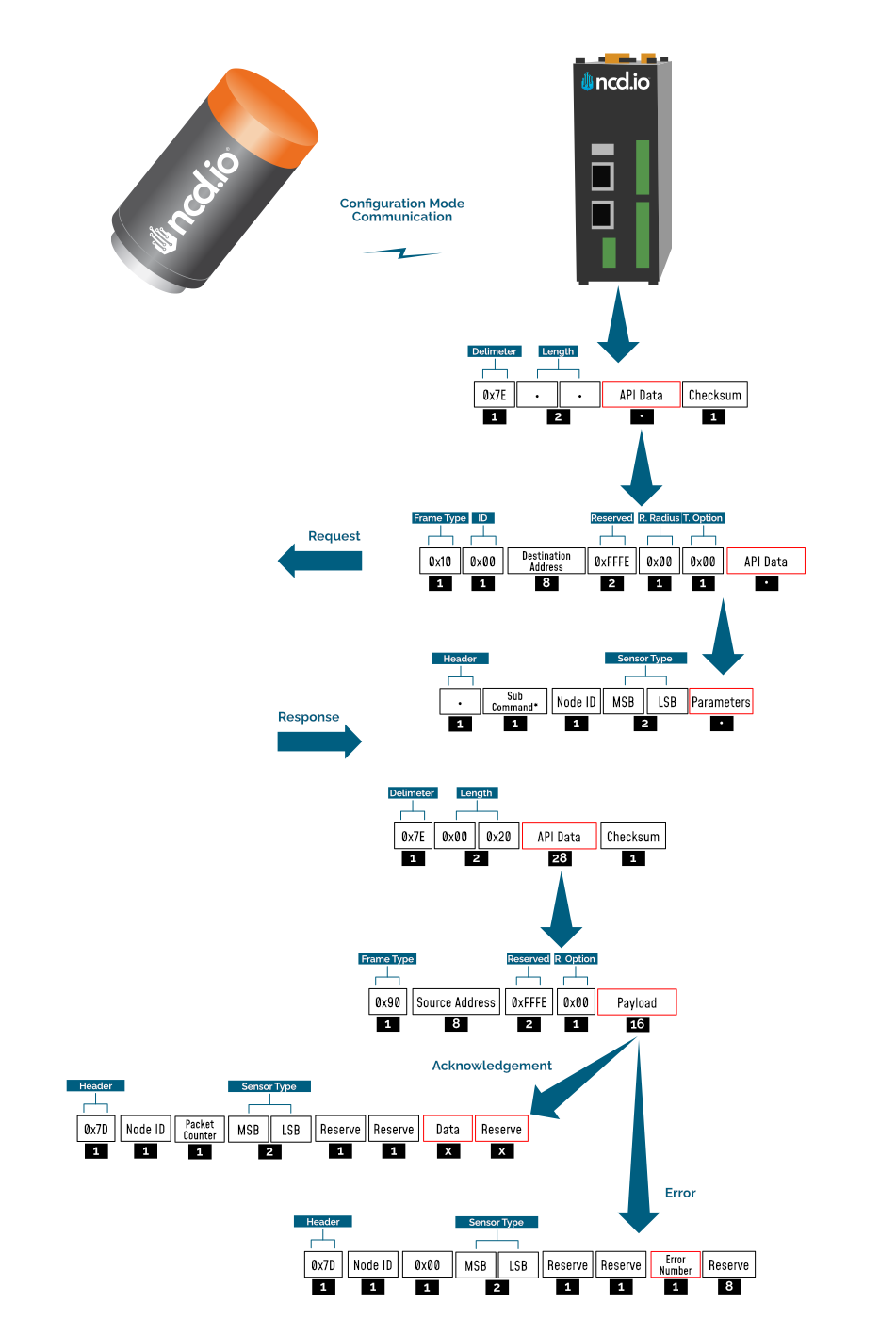
Configuration Mode Frame
Configuration Mode (enter via CFG key press for 7 seconds at power up) is intended to setup the device over the wireless link, you can change parameter values that are subject to change via downlink commands.
When in Configuration Mode a FLY message is sent that if responded to with an OTN message extends the configuration window to 60 seconds so you can push multiple configuration changes.
In configuration mode, the device sets its X-bee pan id to 7BCD. Also, the destination address used by the sensor is extracted from the incoming packet (source address). This ensures that once you put a device in configuration mode you just need to change the PAN ID you are sending to in your Modem/Gateway to match with the sensor and start configuring your device.
A standard configuration packet and its fields are explained in Figure 5. Its possible responses are also shown. The complete set of commands supported by this sensor are shown in тхе Appendix, these can be used in the Parameters field of the Payload section. The sensor responds to these commands with an acknowledgement if the process completed successfully or with an error if it failed to setup a parameter. The respective Data and Reserve section length and values are shown in Table 6 for the case of acknowledgement. In the case of error, the reserved section will be fixed and not used, while the Error number byte will determine the type of error returned. These errors are in a separate section in the Appendix.
Example Configuration Commands
The following set of commands are an example on how to change some of the parameters that affect the operation of the Machine Runtime device (these are parameters that are general in nature, more on a network protocol/device level than device specific). The relate to settings that are independent of the type of probe used. You can find them in Appendix together wit the Device/Application Specific commands.
Read Sleep Duration
This command may be used to read the sensor sleep duration. The sleep duration determines how frequently the sensor wakes up and send sensor data. The interval is set in seconds. Short intervals will drain the battery faster while longer intervals will provide a very long battery life.
Read Sleep Duration Command
7E 00 13 10 00 00 00 00 00 00 00 FF FF FF FE 00 00 F7 15 00 00 00 E8
In the above command the remote device address is set as broadcast. The address is:
00 00 00 00 00 00 FF FF
When sending this command to a particular sensor, replace the MAC address of the sensor. Again, the sensor MUST be in configuration mode.
The Wireless Sensor will respond with the stored delay value:
7E 00 1C 90 00 13 A2 00 41 91 1B 83 FF FE C1 7C 00 02 00 0E 00 00 00 02 58 00 00 00 00 00 00 A6
From the above command, the following data may be extracted:
A. Sensor MAC address
00 13 A2 00 41 91 1B 83
B. Sensor Over-all Payload
7C 00 02 00 0E 00 00 00 02 58 00 00 00 00 00 00
C. Delay Value
0x00 0x02 0x58 (data bytes 23, 24, and 25)
Delay in Seconds = (0x00 x 65536) + (0x02 x 256) + 0x58 = 600 Seconds = 10 Minutes
Set Sensor Node ID and Sleep Duration
This Command may be used to set the sensor node and sleep duration, note that both values are stored together using the same command. The Node ID is a user-defined value from 00 to FF that may be used to help easily identify a sensor. The Sleep Duration indicates the amount of time (in seconds) the sensor will sleep before waking up, taking a sample, sending a transmission, and going back to sleep.
Set Node ID and Sleep Duration Command Example:
7E 00 17 10 00 00 00 00 00 00 00 FF FF FF FE 00 00 F7 02 00 00 00 01 00 01 2C CD
In the above command, the remote device address is set to broadcast mode. The broadcast address is 00 00 00 00 00 00 FF FF, which will target all sensors in configuration mode. Change the broadcast address to the MAC address of a individual sensor to target a particular sensor with this command (this is usually not required). The Command Contains a Sensor payload which contains a Sensor Node ID and Delay value.
Payload
F7 02 00 00 00 01 00 01 2C
Note that F7 is the command header byte and 02 is the sub command for storing the Node ID and Sleep Duration.
A. Node ID
0x01 (Byte 23)
B. New Delay Value
00 01 2C (data bytes 24, 25, and 26)
Delay in seconds = (0x00 x 65536) + (0x01 x 256) + 0x2C = 300 Seconds = 5 Minutes
In the Above command we set the new node to 1 and sleep duration value to 300 seconds (5 Minutes).
Once the sensor receives this command, it will send a response back. This response will indicate success or failure of the command.
In his case, the response will look something like this:
7E 00 1C 90 00 13 A2 00 41 91 1B 83 FF FE C1 7C 01 05 00 0E 00 00 FF 00 00 00 00 00 00 00 00 FD
Read Sensor Network ID
The Network ID is also known as PAN ID (Personal Area Network ID). This feature may be used to build a private Wireless Sensor Network. All sensors with the same Network ID will be able to talk to modems and gateway with the same Network ID. This is useful when deploying hundreds of sensors in one area or applications which require division of sensors, modems, and gateways into different zones with independent monitoring of each zone. Each sensor, gateway, and modem in a specific zone should share identical Network IDs, allowing the separation of sensors into smaller, more manageable groups.
Large factory floors or high-rise building may consist of several groups of sensors working under different Network IDs that help characterize the different areas of the installation. Network IDs make it easy to group sensors, modems, and gateways. When broadcasting data using separate Network IDs, multiple modems and gateways may be used in each zone, allowing sensor data to be collected by several different computers or servers. This kind of redundancy is essential in large installations.
Read Sensor Network ID Command
7E 00 13 10 00 00 00 00 00 00 00 FF FF FF FE 00 00 F7 19 00 00 00 E4
Sensor will respond with the Network ID
7E 00 1C 90 00 13 A2 00 41 91 1B 83 FF FE C1 7C 00 05 00 0E 00 00 7F FF 00 00 00 00 00 00 00 7F
From the above response, following data may be extracted:
A. Sensor MAC Address
00 13 A2 00 41 91 1B 83
B. Complete Sensor Payload
7C 00 05 00 0E 00 00 7F FF 00 00 00 00 00 00 00
C. Network ID
0x07FF (data bytes 23 and 24)
Set Wireless Sensor Network ID
This command may be used to set the sensor Network ID. Please note, Network ID 0x7BCD is reserved for configuration and should NEVER be used as a network ID for general use. Please note the Modem/Gateway must also use a matching Network ID to communicate with the sensor.
Set Wireless Sensor Network ID Command:
7E 00 15 10 00 00 00 00 00 00 00 FF FF FF FE 00 00 F7 05 00 00 00 7C DE 9E
Above Command Contains the following payload:
F7 05 00 00 00 7C DE
Note that F7 is the command header byte and 05 is the sub command for setting the Sensor Network ID.
In the Above command, a new network ID of 0x7CDE is configured.
Once the sensor receives this command, it will send a response back. This response will contain information regarding command success or failure.
In his case the response was successful, responding with the following frame:
7E 00 1C 90 00 13 A2 00 41 91 1B 83 FF FE C1 7C 00 09 00 0E 00 00 FF 00 00 00 00 00 00 00 00 FA
Read Sensor Destination Address
This Command may be used to read the sensor destination address. When the Sensor is in broadcast mode, the destination address will show up as:
0x0000FFFF
This Command may be used to read the sensor destination address.
Read Sensor destination address Command:
7E 00 13 10 00 00 00 00 00 00 00 FF FF FF FE 00 00 F7 18 00 00 00 E5
Sensor will respond with the Stored destination address:
7E 00 1C 90 00 13 A2 00 41 91 1B 83 FF FE C1 7C 00 13 00 0E 00 00 00 00 FF FF 00 00 00 00 00 F1
From the above command, the following data may be extracted:
A. Complete Sensor Payload
7C 00 13 00 0E 00 00 00 00 FF FF 00 00 00 00 00
B. Sensor MAC address
00 13 A2 00 41 91 1B 83
C. Destination Address
0000FFFF (data bytes 23, 24, 25, and 26)
The sensor response 0000FFFF indicates that the sensor is in broadcast mode. Any other value will indicate the sensor is directing its data to a specific address (a specific modem or gateway). We DO NOT ADVISE sending sensor data to a specific address, we advise broadcasting data using different Network IDs (PAN IDs) to put data into clustered zones. Should a specific gateway or modem fail while in service, it will be much easier to deploy a new gateway or setup redundant gateways and modems. Otherwise, reconfiguration of each sensor for a new gateway or modem will be required.
Set Sensor Destination Address
Every sensor is designed to send sensor data either in broadcast mode or to a particular destination address (modem or gateway). By default, NCD sensors broadcast data to all available modems and gateways. Data may be restricted to a single destination address (modem or gateway), though this configuration does not provide any form of redundancy in the event of a Modem or Gateway outage. For this reason, we strongly advise against using this command. Please consider setting the Network ID (PAN ID) to Setup Zones which will allow for redundancy in the event of a service outage. The following command is provided for reference ONLY and should be used with caution as a modem or gateway failure will necessitate reconfiguration of each sensor (which would not be required if the Pan ID/Network ID were used).
What is a Destination Address? Every sensor, gateway, and modem have a unique MAC address which cannot be changed. This MAC address is also known as the destination address (printed on the side of the enclosure). By default, all sensors send data in broadcast mode. This allows all the gateways and modems in the area to receive sensors data provided they are all on the same PAN ID (Network ID) and use the same encryption key.
When a specific destination address is stored in the sensor, the sensor will send data to that specific destination address only. The sensor CANNOT communicate with any other modem or gateway in the area. The following command may be used to specify a specific destination address (modem or gateway) for all sensor data:
Set Destination address Command
This command we will send only the lower 4 bytes of the destination address (the upper 4 bytes do not change).
7E 00 17 10 00 00 00 00 00 00 00 FF FF FF FE 00 00 F7 03 00 00 00 12 34 56 78 E6
The above Command Contains the payload, including a New Sensor destination address:
Complete Payload
F7 03 00 00 00 12 34 56 78
F7 is the command header byte and 03 is the sub command for setting a specific destination address. In this example, the new Destination Address is 12345678.
Once sensor receives this command it will send a response back. This response will indicate the command success or failure.
In his example, the response will look something like this (if successful):
7E 00 1C 90 00 13 A2 00 41 91 1B 83 FF FE C1 7C 00 0E 00 0E 00 00 FF 00 00 00 00 00 00 00 00 F5
High traffic environment Unicast mode
Set Sensor Destination to Broadcast
This Command may be used to set the sensor destination address to broadcast mode, which is the default operation of NCD long range wireless sensors. After setting to broadcast mode, all modems and gateways with the same PAN ID and Encryption key will receive the same sensor data. This is the preferred configuration for all NCD sensors. Segmenting sensors into groups requires a unique PAN ID (also known as Network ID) for each group. All sensors, modems, and gateways must share the same PAN ID for each group.
Set Sensor Destination address to broadcast:
7E 00 13 10 00 00 00 00 00 00 00 FF FF FF FE 00 00 F7 01 00 00 00 FC
Complete Payload
F7 01 00 00 00
F7 is the command header byte and 01 is the sub-command for setting the Destination Address to Broadcast Mode.
Read Wireless Sensor Transmission Power Level
This Command may be used to read the wireless radio transmission power. This value will indicate how much RF power the radio is emitting. The higher the value, the higher the radiated wireless power, resulting in a longer range and decreased battery life (please note that all battery ratings are shown at maximum wireless transmission power). Lower values are desirable in application that may benefit from greatly improve battery life, especially when high power data transmissions are not required.
Read Sensor Power Command:
7E 00 13 10 00 00 00 00 00 00 00 FF FF FF FE 00 00 F7 16 00 00 00 E7
Sensor will respond with the Power Level value:
7E 00 1C 90 00 13 A2 00 41 91 1B 83 FF FE C1 7C 00 09 00 0E 00 00 04 00 00 00 00 00 00 00 00 F5
From the above command, the following data may be extracted:
A. Sensor MAC Address
00 13 A2 00 41 91 1B 83
B. Sensor Payload
7C 00 09 00 0E 00 00 04 00 00 00 00 00 00 00 00
C. Power Level
0x04 (data byte 23)
The sensor will respond with a value from 0x00 to 0x04. The default value is 0x04, allowing for the greatest possible transmission range and the shortest battery life.
Read Wireless Sensor Retries
The following command may be used to read the number of retires. The number of retries is one of the most useful settings for NCD wireless sensors.
Lets say the number of retires is set to 5. In a normal case, the sensor will wake up, gather data, send data to the modem, and go back to sleep. But due to some environmental issues (lets say a few trucks were driving by and they came in between the sensor and the modem) the modem didn’t receive the data. In that case, the sensor will try 4 more times to send the data. If the modem still doesn’t get the data after all 5 tries, the sensor will quite trying and will go back to sleep. The Machine Runtime sensor will wake up after the predefined sleep time and will try again.
The highest number of retries allowed is 10.
Read The number of Sensor Retries:
7E 00 13 10 00 00 00 00 00 00 00 FF FF FF FE 00 00 F7 17 00 00 00 E6
Sensor will respond with the Retries value:
7E 00 1C 90 00 13 A2 00 41 91 1B 83 FF FE C1 7C 00 1B 00 0E 00 00 0A 00 00 00 00 00 00 00 00 DD
From the above command, the following data may be extracted:
A. Sensor MAC Address
00 13 A2 00 41 91 1B 83
B. Complete Sensor Payload
7C 00 1B 00 0E 00 00 0A 00 00 00 00 00 00 00 00
C. Retries Number
0x0A (data byte 23)
Set Wireless Sensor number of Retries
This Command may be used to change the number of retries. The highest number of retries allowed is 10:
7E 00 14 10 00 00 00 00 00 00 00 FF FF FF FE 00 00 F7 06 00 00 00 05 F2
The above Command Contains a Sensor payload which contains a new number of retries value:
Complete Payload
F7 06 00 00 00 05
F7 is the command header byte and 06 is the sub command for setting the Retries value.
In the Above command we set the retries value to 5 (byte 23).
Once the sensor receives this command, it will send a response back. This response will contain the info regarding command success or failure.
In his case the response was successful:
7E 00 1C 90 00 13 A2 00 41 91 1B 83 FF FE C1 7C 00 1D 00 0E 00 00 FF 00 00 00 00 00 00 00 00 E6
Set Wireless Sensor Encryption Key
This Command may be used to set the encryption key.
All ncd.io wireless sensors comes with 128bit AES encryption. The default encryption key secures a wireless sensor network of sensors, modems, and gateways. Users have the option to change the default encryption key. Please note this is a Write ONLY operation, it is not possible to read the encryption key from Sensors, Modems, or Gateways. Be Sure to keep records accordingly.
Once the sensor encryption key is set in the sensor, be sure to set the same key in all modems and gateways. If the modem or gateway doesn’t have the same key and PAN id as the sensor, there will be no way for sensors to communicate with modems or gateways. In this event, only a factory reset may be used to recover communications.
The following Command may be used to change the encryption key:
7E 00 24 10 00 00 00 00 00 00 00 FF FF FF FE 00 00 F2 03 00 00 00 00 55 AA 55 AA 55 AA 55 AA 55 AA 55 AA 55 AA 55 AA 07
Complete Payload
F2 03 00 00 00 00 55 AA 55 AA 55 AA 55 AA 55 AA 55 AA 55 AA 55 AA
F2 is the command header byte and 03 is the sub command for setting the ENY Key value.
Note — There is an Extra 0x00 Right before the ENY key value. Its a reserve byte and it should be there all the time.
In the Above command, the default ENY Key value is programmed into the NCD sensor.
55 AA 55 AA 55 AA 55 AA 55 AA 55 AA 55 AA 55 AA
Once the sensor receives this command, it will change the Key immediately.
In the event a key value is lost, factory reset the device. The default key value will always be used after factory reset:
55 AA 55 AA 55 AA 55 AA 55 AA 55 AA 55 AA 55 AA
Troubleshooting
Here are some common issue one might encounter when first setting up the sensor or later on when advance configuration is performed:
1. No or low range/coverage. Data is not received by the Modem/Gateway. Make sure you have properly installed the antenna and have as little obstructions/metal surrounding the sensor.
2. Measurement data missing or values are inconsistent. This might be due to not installing/tightening the probe correctly. Make sure you screw it in all the way and that you position it appropriately where you want to perform the measurements,
3. In case data is not being received (was previously received) there might be a power issue. Check the batteries and or the status of the internal LEDs. You can also observe the battery voltage value in the Run Mode packets you last received to know if the batteries have diminished too much for the sensor to operate.
4. If there are connectivity issue where data is being received intermittently or packets are being lost/need retransmission, make sure that you are in a RF heavy noise environment and/or the sensor is not separated too far away from the nearest node. You might need to install more nodes to bust coverage. Check if the Modem/Gateway is powered properly and operation and its antenna has been installed properly.
5. In case you still can’t solve your issue head to our Community forum to get real time help from the NCD community of experts: https://community.ncd.io/
Appendix
Configuration Commands
Node-RED can be used to configure the device (check the Quick Start section), however you can use any tool as long as you adhere to the proper command structure described in this chapter.
Refer to the table below for a list of commands, their codes and an explanation of what parameter they affect.
| No. | Command | Header | Sub Command | Parameter Field | Default Value | Description |
|---|---|---|---|---|---|---|
| 1 | Set Broadcast Transmission | 0XF7 | 0x01 | - | 0000FFFF | This will set the address to Broadcast mode. All the receiver with same ENY key and PAN ID will get the data packets |
| 2 | Set ID and Sleep Interval | 0XF7 | 0x02 | NODE ID, D0 MSB,D1, D2 LSB | 0x00,0x00,0x02,0x58 | Sets the Device node ID and Data Transmission Interval. The node id value can go from 0-255 and The Data transmission value can go from 3-0xFFFFFF Seconds |
| 3 | Set Destination Address | 0XF7 | 0x03 | A0 MSB, A1, A2, A3 | 00,00,FF,FF | Sets the Destination Address of the sensor. The sensor will send Run mode Data packets to this Address |
| 4 | Set Power | 0XF7 | 0x04 | Power ( range 1-4) | 0x04 | Sets the RF power of the Sensor Radio |
| 5 | Set PAN ID aka Network ID | 0XF7 | 0x05 | ID0 MSB, ID1 LSB | 0x7FFF | Sets the PAN ID aka Network ID in the sensor. Only sensors, Gateway, and Modes with Same ID can communicate with each other |
| 6 | Set Retries | 0XF7 | 0x06 | Retries | 0x0A | Sets the number of Retries after unsuccessful transmission for the Sensor Radio |
| 7 | Read Sleep Interval | 0XF7 | 0x15 | - | 0x00,0x02,0x58 | Reads the stored Sleep Interval value from the sensor |
| 8 | Read Power | 0XF7 | 0x16 | - | 0x04 | Reads the stored RF Power value from the sensor |
| 9 | Read Retries | 0XF7 | 0x17 | - | 0x0A | Reads the stored Retries value from the sensor |
| 10 | Read Destination Address | 0XF7 | 0x18 | - | 00,00,FF,FF | Reads the stored Destination value from the sensor |
| 11 | Read PAN ID aka Network ID | 0XF7 | 0x19 | - | 0x7FFF | Reads the PAN ID aka Network ID |
| 12 | Enable Encryption | 0XF2 | 0x01 | - | 0x01 | Enables the Encryption of the Frame Transmitted from the Sensor |
| 13 | Disable Encryption | 0XF2 | 0x02 | - | - | Disables the Encryption of the Frame Transmitted from the Sensor |
| 14 | Set Encryption Key | 0XF2 | 0x03 | 00,K0 MSB, K1,K2,K3,K4,K5,K6,K7,K8,K9,K10,K11,K12,K13,K14,K15 | 55AA55AA55AA55AA55AA55AA55AA55AA | Sets the 128 bit AES Encryption Key |
| 15 | Set Change Detection Parameters | 0XF7 | 0x07 | E, PR, T0 MSB, T1, T2 LSB | Enable or disable the percentage change detection. E=1 (Enable), E=0 (Disable) PR is the percentage change detection at which the sensor will send a packet. The sensor sends a packet when two consecutive readings differ by PR percent T0, T1, T2 - This is the detection time after which the sensor periodically checks for PR percent change in sensor data from last sample |
|
| 16 | Read Change Detection Parameters | 0XF7 | 0x1A | - | Refer to Command 15 above for the explanation. |
Command Acknowledgement Data
Each command (Appendix A) has its corresponding Acknowledgement with a specific format, size, sections, etc. Use the table below as reference for the parameter values.
| No. | Command | Data bytes | Reserved bytes | Data | Calculation (if any) |
|---|---|---|---|---|---|
| 1 | Set Broadcast Transmission | 1 | 8 | 0xFF (OK) | |
| 2 | Set ID and Sleep Interval | 1 | 8 | 0xFF (OK) | |
| 3 | Set Destination Address | 1 | 8 | 0xFF (OK) | |
| 4 | Set Power | 1 | 8 | 0xFF (OK) | |
| 5 | Set PAN ID aka Network ID | 1 | 8 | 0xFF (OK) | |
| 6 | Set Retries | 1 | 8 | 0xFF (OK) | |
| 7 | Read Sleep Interval | 3 | 6 | D0 MSB, D1, D2 LSB | Delay = (D0 x 65536) + (D1 x 256) + D2 |
| 8 | Read Power | 1 | 8 | Power | DEC value |
| 9 | Read Retries | 1 | 8 | Retries | DEC value |
| 10 | Read Destination Address | 4 | 5 | A0 MSB, A1, A2, A3 | |
| 11 | Read PAN ID aka Network ID | 2 | 7 | ID0 MSB, ID1 | |
| 12 | Enable Encryption | 1 | 8 | 0xFF (OK) | |
| 13 | Disable Encryption | 1 | 8 | 0xFF (OK) | |
| 14 | Set Encryption Key | 1 | 8 | 0xFF (OK) | |
| 15 | Set Change Detection Parameters | 1 | 8 | 0xFF (OK) | |
| 16 | Read Change Detection Parameters | 5 | 4 | E, PR, T0, T1, T2 | Detection time = (T0 x 65536) + (T1 x 256) + T2 |
Application Specific Commands
| No. | Command | Header | Sub Command | Reserve Byte | Command Code / Argument | Description |
|---|---|---|---|---|---|---|
| 1 | Set Clear Counters | 0xF4 | 0x24 | 0x00, 0x00, 0x00 | 0x10 -- Magnetometer 0x08 -- Accelerometer | Clear the counters on specific digital input. |
| 2 | Read Clear Counters | 0xF4 | 0x25 | 0x00, 0x00, 0x00 | 0x10 -- Magnetometer 0x08 -- Accelerometer | Read the counters on specific digital input. |
| 3 | Set Debounce Time | 0xF4 | 0x27 | 0x00, 0x00, 0x00 | Valid Range: 0x000A -- 0xFDE8 | Sets the debounce time in milliseconds on inputs. State changes to the input during this debounce time will be ignored. Generally recommended for mechanically triggered state changes such as button or relay/contactor outputs. |
| 4 | Read Debounce Time | 0xF4 | 0x28 | 0x00, 0x00, 0x00 | Read the debounce time in milliseconds on inputs. | |
| 5 | Set Counter Threshold | 0xF4 | 0x2B | 0x00, 0x00, 0x00, 0x00, 0x00 | Valid Range: 0x0000 -- 0xFFFE | Device will send data when any counters reaches multiple of the Threshold. Note: The range for this value is from 0 to 65534 and must be multiple of 100. |
| 6 | Read Counter Threshold | 0xF4 | 0x2C | 0x00, 0x00, 0x00, 0x00, 0x00 | ||
| 7 | Enable Push Notification | 0xF4 | 0x2D | 0x00, 0x00, 0x00 | 0x00 -- Disable All 0x18 -- Enable All 0x08 -- Enable on Accelerometer 0x10 -- Enable on Magnetometer | Enable the push notification, sensor will transmit data immediatelly when the selected input is enabled. The Message Type will be 'Interrput' in sensor data |
| 8 | Read Push Notification | 0xF4 | 0x2E | 0x00, 0x00, 0x00 | 0x00 -- Disable All 0x18 -- Enable All 0x08 -- Enable on Accelerometer 0x10 -- Enable on Magnetometer | Read the push notification. |
| 9 | Set Data Transmission Interval | 0xF4 | 0x37 | 0x00, 0x00, 0x00 | 0x00 -- 1 Minute 0x01 -- 5 Minutes 0x02 -- 15 Minutes 0x03 -- 30 Minutes 0x04 -- 1 Hour 0x05 -- 2 Hours 0x06 -- 3 Hours 0x07 -- 6 Hours 0x08 -- 12 Hours 0x09 -- 5 Seconds 0x0A -- 10 Seconds 0x0B -- 15 Seconds 0x0C -- 30 Seconds | This setting dictates the interval at which the sensor will wake up and transmit its data. This interval works independently from any configured interrupt driven messages. |
| 10 | Read Data Transmission Interval | 0xF4 | 0x38 | 0x00, 0x00, 0x00 | 0x00 -- 1 Minute 0x01 -- 5 Minutes 0x02 -- 15 Minutes 0x03 -- 30 Minutes 0x04 -- 1 Hour 0x05 -- 2 Hours 0x06 -- 3 Hours 0x07 -- 6 Hours 0x08 -- 12 Hours 0x09 -- 5 Seconds 0x0A -- 10 Seconds 0x0B -- 15 Seconds 0x0C -- 30 Seconds | Read the interval at which the sensor will wake up and transmit its data. |
| 11 | Reset Timeout | 0xF4 | 0x31 | 0x00, 0x00, 0x00 | Valid Range: 0x0000 -- 0xFFFE | Sensor will reset after this time and before reset it will set it data value. |
| 12 | Read Reset Timeout | 0xF4 | 0x32 | 0x00, 0x00, 0x00 | ||
| 13 | Set Shift Time 1 | 0xF4 | 0x2F | 0x00, 0x00, 0x00, 0x00 | 0x00 -- Hour, 0x00 -- Minute | Based on the RTC (Real-Time Clock). Set 1 of 4 specific times (24-hour time format) in which the sensor will apply a reset. |
| 14 | Set Shift Time 2 | 0xF4 | 0x2F | 0x00, 0x00, 0x00, 0x01 | 0x00 -- Hour, 0x00 -- Minute | Based on the RTC (Real-Time Clock). Set 2 of 4 specific times (24-hour time format) in which the sensor will apply a reset. |
| 15 | Set Shift Time 3 | 0xF4 | 0x2F | 0x00, 0x00, 0x00, 0x02 | 0x00 -- Hour, 0x00 -- Minute | Based on the RTC (Real-Time Clock). Set 3 of 4 specific times (24-hour time format) in which the sensor will apply a reset. |
| 16 | Set Shift Time 4 | 0xF4 | 0x2F | 0x00, 0x00, 0x00, 0x03 | 0x00 -- Hour, 0x00 -- Minute | Based on the RTC (Real-Time Clock). Set 4 of 4 specific times (24-hour time format) in which the sensor will apply a reset. |
| 17 | Set Reset Mode | 0xF4 | 0x33 | 0x00, 0x00, 0x00 | 0x00 -- Do not reset counters 0x01 -- Based on Shift Ends 0x02 -- Based on the Timeout Provided | This works in conjunction with Reset Timeout and Shift Time commands. It specifies which reset option the sensor will apply. Default value: Disabled |
| 18 | Enable Quality of Service | 0xF4 | 0x34 | 0x00, 0x00, 0x00 | 0x00 -- Disable 0x01 -- Enable | This setting only functions when a Destination Address is also configured into the sensor. If QoS is enabled the sensor will wait for a receipt acknowledgement from the intended receiver before resuming sleep. If no receipt acknowledgement is received the sensor will one more time to transmit the data. |
| 19 | Set Internal Real Time Clock | 0xF4 | 0x35 | 0x00, 0x00, 0x00 | 0x00 -- Hour, 0x00 -- Minute, 0x00 -- Second | Sets the internal Real Time Clock |
| 20 | Set FLY Interval | 0xF7 | 0x38 | 0x00, 0x00, 0x00 | 0x3C -- 1 Hour 0x78 -- 2 Hours 0xF0 -- 4 Hours 0x01E0 -- 8 Hours 0x02D0 -- 12 Hours 0x0438 -- 18 Hours 0x05A0 -- 24 Hours | This setting dictates the interval at which the sensor will wake up and transmit the FLY message. FLY Message is used to trigger Automatic Sensor configuration and Firmware Update. |
| 21 | Enable Accelerometer | 0xF4 | 0x25 | 0x00, 0x00, 0x00 | 0x01 -- Enabled 0x00 -- Disabled | |
| 22 | Enable Accelerometer Error Reporting | 0xF4 | 0x25 | 0x00, 0x00, 0x00, 0x07 | 0x01 -- Enabled 0x00 -- Disabled | Enables the sensor to report errors if the accelerometer probe becomes non-functional. These errors will be included in the sensor data. |
| 23 | Accelerometer Threshold | 0xF4 | 0x20 | 0x00, 0x00, 0x00 | Valid Range: 0x00 -- 0xFF | The sensor will transmit data when any connected counter reaches a multiple of this threshold value. **Report type will be 'Threshold'. Note: The range for this value is from 0 to 65534 and must be multiple of 100. |
| 24 | Configured Enabled Axes | 0xF4 | 0x48 | 0x00, 0x00, 0x00 | 0x01 -- X Axis 0x02 -- Y Axis 0x04 -- Z Axis 0x07 -- All Axes 0x00 -- Disabled All | |
| 25 | Raw Accelerometer Data | 0xF4 | 0x46 | 0x00, 0x00, 0x00 | 0x01 -- Enabled 0x00 -- Disabled | Device will send 10 samples of acceleration data for each axis. This feature is only available for devices with 868MHz and 900MHz radios. |
| 26 | Accelerometer Sample Rate | 0xF4 | 0x39 | 0x00, 0x00, 0x00 | 0x00 -- 10Hz 0x01 -- 20Hz 0x02 -- 50Hz 0x03 -- 100Hz 0x04 -- 200Hz 0x05 -- 400Hz | |
| 27 | Set Interrupt Timeout | 0xF4 | 0x41 | 0x00, 0x00, 0x00 | Valid Range: 0x0000 -- 0xFFFE | Set the sensor to detect an initial IO (input/output) change and not transmit subsequent IO changes for a specified duration; set the duration value to control how long changes are ignored in milliseconds, set it to 0 to disable ignoring. **Only applies to sensor with firmware version 11 and above. Valid range: 0 - 65000 milliseconds. |
Error Code Descriptions
Here a summary is provided of what the different error codes mean (in case a valid Ack has not been received).
| Error Number | Description |
|---|---|
| 0x01 | Invalid command |
| 0x02 | Sensor Type mismatch |
| 0x03 | Node ID mismatch |
| 0x04 | Apply change command failed during X-bee parameter update |
| 0x05 | Invalid API packet command response received after Apply change command |
| 0x06 | Write command failed during X-bee parameter update |
| 0x07 | Invalid API packet command response received after Write command |
| 0x08 | Parameter change command failed during X-bee parameter update |
| 0x09 | Invalid Parameter change command response packet received after Write command |
| 0x0A | Invalid/Incomplete packet received |
| 0x0F | Invalid parameter for setup/saving |
Frame Checksum Calculation
In order to successfully communicate over the API protocol, the checksum is of vital importance. The X-bee at either end of the link will reject packets if the checksum does not match.
Calculation for transmission
For sending packets, the checksum calculation works as follows:
1. Not including the frame delimiter and length, add all the bytes and keep the lower 8 bits of result
2. Subtract this value from 0xFF (hex)
3. The resultant value is the checksum
4. Append this byte to the original packet for sending
Consider the example for the command Set Broadcast shown in APPENDIX A and see that the calculated checksum matches with the checksum sent by the terminal/LabVIEW. Let us break the example command below:
7E00 1310 0000 0000 0000 00FF FFFF FE00 00F7 0100 0001 FB
If we extract the relevant bytes from the command we get:
10 0000 0000 0000 00FF FFFF FE00 00F7 0100 0001
Adding the bytes and taking the last 8 bits yields:
0x04
Substract the value obtained (0x04) from 0xFF
0xFF-0x04=0xFB
We get a value matching the one in the packet checksum field.
Calculation for reception
Although checksum is matched by the X-bee itself, but for understanding follow these steps to match checksum at reception
1. Not including the frame delimiter and length, add all the bytes including the received checksum
2. Keep only the last 8 bits
3. If the result is 0xFF, the checksum is correct and the packet can be processed.
Consider the example for the command Set Broadcast shown in APPENDIX A and see that the received packet checksum verifies since the result is 0xFF.
7E00 1C90 1310 A200 4158 1CCB FFFE C17C 000D 0001 0000 FF00 0000 0000 0000 00F3
If we extract the relevant bytes from the command we get:
90 1310 A200 4158 1CCB FFFE C17C 000D 0001 0000 FF00 0000 0000 0000 00F3
Adding the bytes and taking the last 8 bits yields:
0xFF