- Introduction
- Overview
- Requirements
- Modes of operations
- Getting started.
- Summary
Introduction
In this document, we will guide you step-by-step on how to configure the NCD Vibration Sensor to operate in processed and Time Domain Data on-demand mode using Node-RED. We’ll share important tips to consider and demonstrate how to import, connect, and set up a practical subflow in your current workspace. This subflow allows you to request Time Domain data by sending a specific command in an easy and intuitive way.
By default, the vibration sensor is preconfigured in Processed mode only. This means it sends data derived from processing its measurements at user-defined intervals. During each interval, the sensor samples acceleration across the x, y, and z axes multiple times per measurement. These samples are then used to calculate the processed values that are typically of most interest to users.
Note: every message also reports the sampling rate in Hz (odr) and the temperature of the probe.
This data is likely more than sufficient to identify potential issues with the machinery. By analyzing the frequency peaks, you can also deduce the root cause—whether it’s misalignment, imbalance, worn bearings, or another issue.
In some cases, this information might not be sufficient, or you may want to access the raw measurement data for storage and separate processing. This is referred to as Time Domain Data mode. It includes every measured value across the three axes for all the samples—amounting to thousands of data points.
This data can be used for detailed analysis, such as performing a Fast Fourier Transform (FFT) to obtain the full spectrum of the vibrational signature at the time of measurement.
Overview

Requirements
- An Industrial IoT Wireless Vibration Sensor.
- The Enterprise IIoT Gateway or the Industrial IIoT NCD Modem.
- Node-RED and NCD Library installed.
Modes of operations
Using Node-RED and the NCD Library, you can configure the operation mode of the vibration sensor. These sensors can be set to function in one of three modes: Processed, Raw (Time Domain Data), or Processed + Raw On Demand. By default, the sensor operates in Processed mode. Below is a detailed explanation of each mode:
Processed Mode
This is the default operating mode of the vibration sensor, where only processed data is sent. In this mode, a Fast Fourier Transform (FFT) is performed by the sensor, and the measurement data is presented in a condensed form. This includes both time-domain and frequency-domain parameters, making it suitable for quick diagnostics and standard monitoring tasks.
Time-Domain Data Mode
In Time Domain Data (Raw Mode), the vibration sensor sends the full time-domain data collected during measurements. This mode provides unprocessed data, making it ideal for advanced analysis and custom processing. However, the transmitted data packets are significantly larger compared to Processed Mode, and continuous use is not recommended for prolonged periods due to the high data load.
When using Time Domain Data (Raw Mode), it is the client’s responsibility to perform the Fast Fourier Transform (FFT) or other desired processing. For example, you can leverage a Node.js implementation of an FFT library within Node-RED to analyze the raw data. This mode is particularly useful for scenarios requiring detailed insights, such as analyzing vibrational signatures or creating custom frequency-domain visualizations.
Processed + Time Domain Data On Demand Mode
In this mode, the sensor operates similarly to the default Processed Mode by sending processed data at regular user-defined intervals. However, it adds the flexibility of requesting a Time Domain Data packet on demand.
After transmitting the processed data to the gateway, the sensor remains active for a brief moment to check for a Time Domain Data request. If the sensor receives the specific request command during this window, it sends the Time Domain Data packet. Once the Time Domain Data transmission is complete, the sensor returns to its low-power sleep state.
This mode provides the convenience of regular processed data while enabling occasional detailed analysis through raw data, offering a balance between data precision and power efficiency.
Getting started.
Node-RED
Node-RED, is a visual programming tool, It provides a browser-based editor that allows creating applications by wiring predefined black box functions (nodes) . Despite its technical nature, Node-RED offers a user-friendly interface. Node-RED is an open-source project under the OpenJS Foundation. This means it’s free to use, without any monthly subscription fees. You can install and run Node-RED locally on your PC, or, in the case of our Enterprise IIoT Gateway, it comes pre-installed and runs as a service.
NCD Library
This library facilitates both communication with and configuration of the NCD Wireless Sensor Line. It includes “Wireless Gateway,” “Wireless Device,” and “ncd-gateway-config” nodes. The “Wireless Device” node is specifically designed to configure sensor parameters in an intuitive and graphical way.
Accessing Node-RED on The Enterprise IIoT Gateway.
To set up and connect the NCD sensor with the Enterprise IIoT Gateway and access the Node-RED interface, please refer to the following article:
NCD Basic Node-RED Flow
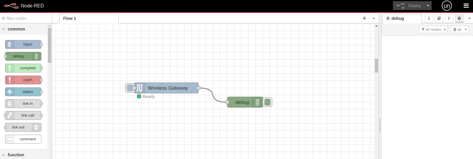
This is a preconfigured flow, meaning it is ready to receive data from the NCD sensors. When a new NCD sensor connects to the wireless network and sends data, the “Wireless Gateway” node automatically receives and processes the message. It then sends the message through its output terminal, and the message flows through the connection cable to the “Debug” node. This node receives the message and displays it in JSON format inside the “Debug” window on the right side of the Node-RED editor.
Checking Communication
Once the Enterprise IIoT Gateway is configured and connected, power on the Vibration Sensor. The sensor will automatically connect to the gateway and begin sending messages. These messages not only include the vibration data, but also provide important information about the sensor, including the current mode of operation.
When the sensor is powered on, you should be able to see the following messages in the Debug window in Node-RED:
- RUN
- FLY
- sensor_data
These messages contain valuable details about the sensor’s status and operational mode, helping you confirm that the sensor is properly communicating with the gateway.

Here’s a brief description of the key messages from the Vibration Sensor:
RUN Message: The RUN message indicates that the Vibration Sensor, identified by the msg.payload.mac address, is powered on and successfully communicating with the wireless network. This confirms that the sensor is active and ready to transmit data.
FLY Message: The FLY message shows that the sensor is in RUN mode but temporarily enters a state where it can be configured. The sensor sends a FLY message upon boot and then every hour afterward as a regular check-in to confirm its status and readiness for configuration.
sensor_data Message: The sensor_data message is the primary message sent from the Wireless Gateway Node. These messages can be identified by the topic field, which will always be labeled as sensor_data. This message contains the actual vibration and temperature data sent by the sensor.
This message contains key information about the NCD sensor that generated it. It includes data such as the Node ID, Firmware Version, Battery Voltage, Battery Percentage, Counter, Sensor Type, values of the field variables the sensor is measuring and transmitting (msg.payload.sensor_data), the sensor’s Name, the MAC Address of the radio frequency module used for transmission, the precise time at which the message was received, the original message (in HEX format), and the RSSI Signal Quality (if enabled within the Wireless Gateway node).
msg.payload.sensor_data
The msg.payload.sensor_data message, contains the actual measurement data from the NCD Vibration Sensor. This message includes the values of the field variables, which could either be Processed or Time Domain Data depending on the mode of the sensor.
Processed Mode: In this mode, the data is already processed by the sensor, including time and frequency parameters, making it more compact and easier to analyze without needing additional processing on the client side.
Time Domain Data Mode: When in Time Domain Data mode, the sensor sends raw measurement data for each sample across the X, Y, and Z axes, which can then be used for further analysis like performing Fast Fourier Transform (FFT) or other advanced signal processing techniques.
Configuring Vibration Sensor
As previously mentioned, the NCD Vibration Sensor comes preconfigured in Processed mode from the factory. To enable the ability to request Time Domain Data from the sensor, you will need to configure the sensor and set it to Processed + Time Domain Data On Demand mode using Node-RED and the Wireless Device Node.
By default, the NCD sensors are set to broadcast transmission mode. In broadcast mode, the same data is transmitted to all nodes on the network. These transmissions are propagated throughout the entire network, ensuring that all available nodes receive the transmitted data. While this is useful for general data distribution, it may not be the most efficient mode for requesting Time Domain Data vibration.
To optimize performance when working with Time Domain Data, we highly recommend configuring the sensor to unicast transmission. Unicast transmission sends messages to a single node (either a Gateway or Modem) on the network, identified by a unique 64-bit address. This ensures that the data is sent directly to the intended recipient, reducing unnecessary network traffic and improving data transfer efficiency.
Setting the destination address to unicast ensures that all the Time Domain Data vibration data is delivered directly to the Gateway through a reliable checking mechanism. In Time Domain Data mode, the sensor transmits around 200 packets at once. This method improves data accuracy and reduces the risk of packet loss, as it sends data to a specific destination rather than broadcasting it to all nodes on the network. This setup ensures more efficient communication, especially when dealing with large volumes of Time Domain Data.
Wireless Device node
The NCD Node-RED library provides a straightforward way to configure any NCD sensor using the “Wireless Device” node. This can be done by adjusting a few fields in your Node-RED flow and triggering the configuration mode. You can initiate this mode either by pressing the RESET and CFG buttons on the sensor, or by waiting for a FLY message to be sent from the sensor.
To configure your sensor via Node-RED, refer to the following documentation for detailed instructions:
This guide will walk you through the step-by-step process of configuring your sensor using Node-RED. All of our Industrial IoT Wireless Vibration Sensors support OTF (Over The Fly) configuration, so you can follow this method to configure your sensors.
Processed + Raw On Demand mode
Destination Address
Payload Length
NCD Vibration Sensors User Manual:
Checking sensor_data mode 2
Once you have performed the configuration, the sensor will automatically reset and begin sending sensor data. Alternatively, you can trigger a sensor transmission by pressing the RESET button on the sensor. Afterward, check the sensor data in the debug window. Expand the sensor_data message by clicking on the message in the debug window, and you should see the ‘mode’ property defined as ‘2’, as shown in the following image:

Import the NCD Subflow request
Click on the following link to access the NCD Filter Node source code. NCD Filter Node Github Repository:

Once the repository is open, locate the button that allows you to copy the raw code of the NCD Filter Node.
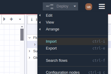
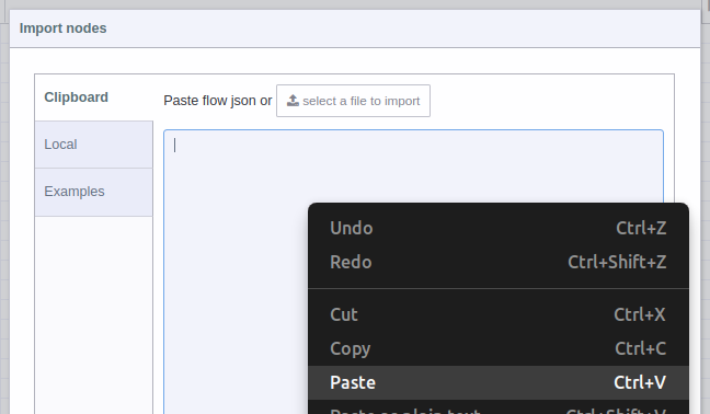
With the NCD Filter Node source code copied, head back to the Node-RED node editor and follow these next steps carefully:
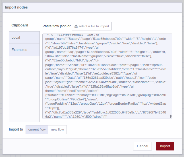
3. You should see the JSON code in text-box, now you can press the red “Import” button at the bottom right (by default the “current flow” option is selected):

NCD Raw Request Nodes
ncd-raw-request: This is the primary node that manages the Time Domain Data (RAW) request process. It is designed to handle and filter sensor data messages by checking the msg.topic property. The node ensures that the sensor type is valid, supporting only sensor types 80, 81, and 84. After validation, it sends the request command to the sensor using the configured MAC address. In its second output, the node will transmit the Time Domain Data (RAW) message as soon as it is received from the sensor.
Debug nodes: The Request Command Debug Node displays the command request in the debug window, providing visibility into the transmitted request. The Request Address Debug Node shows the actual MAC address of the sensor to which the command is being sent, ensuring proper targeting of the request.
RAW Data debug node: Once the Time Domain Data (RAW) request is successfully configured and the vibration sensor sends the Time Domain Data (RAW) Vibration message, you will see this incoming data displayed in the debug window through this node. You can use Terminal 2 of the ncd-raw-request node to create a flow for processing the raw data as needed.
Connection Flow
The next step is to establish the connection. First, connect the output of the Wireless Gateway node to the input of the ncd-raw-request node, as shown in the following image:

Then, you can move the link in 1 node closer to the input terminal of the Wireless Gateway node by using the mouse.

Next, connect the output of the link in 1 node to the input of the Wireless Gateway node.

To save and apply any changes made in the Node-RED node editor, simply click on the Deploy button.

You should see something like the following: the ncd-raw-request node will display a status message saying Invalid Address. This occurs because the Sensor Address property has not been defined yet. Before setting the Sensor Address, let’s review the properties of the node.

ncd-raw-request properties
If you double-click on the ncd-raw-request node, you will access its properties. This node has four configurable properties:
- Name: You can assign an identifier to the node to easily recognize and manage it in your Node-RED workspace.
- Sensor Address: This property allows you to set and register the MAC address of the NCD vibration sensor from which you want to request Time Domain Data (RAW). The node automatically stores this value. When you request raw data, the node checks if the MAC address is registered. If it is, the node will send the RAW request. If the address is not registered, no action is taken. This property allows you to request RAW data from multiple vibration sensors, as long as their MAC addresses are registered. In the next chapter, we will explain this with an example. The node will also validate if the entered MAC address is valid; if not, it will show an ‘Invalid Address’ message. A valid MAC address example is: ‘00:13:A2:01:02:03:04:05’.
- Request Probe 1 (Applicable for Sensor Type 81 – Two-Channel Vibration Plus): This property enables or disables the RAW data request for probe 1. When enabled, the node will automatically add the command to request RAW data for probe 1.
- Request Probe 2 (Applicable for Sensor Type 81 – Two-Channel Vibration Plus): This property enables or disables the RAW data request for probe 2. When enabled, the node will automatically add the command to request RAW data for probe 2.
If both Request Probe 1 and Request Probe 2 are enabled, the node will send command requests for both probes (probe 1 and probe 2). (Apply for type 81 – Two Channel Vibration Sensor)
If you are using the Two-Channel Vibration Sensor and do not enable any of the probes, when new sensor data is received, the node will display a warning message indicating that you need to select at least one probe in order to request RAW data. This ensures that the node knows which probe’s data to request.
The first thing you need to do is set the Sensor Address property. This Sensor Address should correspond to the Vibration Sensor from which you want to request RAW data. To obtain the sensor’s MAC address, you need to wait for a sensor data message or force a transmission by pressing the reset button. Once you receive the data, expand the sensor_mode or sensor_data message, and locate the sensor’s MAC address in the ‘addr’ property. To copy the value, position the cursor over the property and click the ‘copy value’ button, as shown in the following image:
Immediately, the status of the node will change to ‘Ready’, indicating that the ‘ncd-raw-request’ node is in standby mode, awaiting a ‘sensor_data’ processed message. Once the message is received, the node will build and send the RAW data request command to the sensor, using the specified Sensor Address.
To test the functionality, you can either wait for the next sensor data message or force a new sensor transmission by resetting the sensor. As mentioned, once the node receives the sensor data message, it will build and send the request for Time Domain Data (RAW). You should see the ‘Sending Request’ status on the node. Afterward, the ‘Request Address’ debug node will display the MAC address of the vibration sensor to which the request command was sent.
As mentioned earlier, if you are using a Two Channel Vibration Sensor, you can select the individual probe from which you want to request RAW data. For example, we will demonstrate how to request raw data from Probe 2 by activating the “Request Probe 2” property and disabling the “Request Probe 1” property.
- Enable “Request Probe 2”: Check the box to enable the RAW data request for Probe 2.
- Disable “Request Probe 1”: Uncheck the box to disable the RAW data request for Probe 1.
Once these settings are configured, the ncd-raw-request node will send the request specifically for Probe 2’s RAW data.
After making these changes, click “Done” to apply the modifications. You can then click the “Deploy” button to save the updated flow. When the next sensor data message is received, the node will request the RAW data from Probe 2, and you’ll be able to see the corresponding raw data packets in the debug window.
As soon as a new sensor data message arrives from the Two Channel Vibration Sensor, the ncd-raw-request node will now send the request command specifically for Probe 2. You will see the following sequence of events:
- The “Sending Request” status will appear in the debug node.
- The Request Address debug node will display the MAC address of the sensor from which the request command was sent.
- The Time Domain Data (RAW) packets for Probe 2 will begin to arrive in the debug window, with the “Receiving RAW” status node showing up.
The Vibration sensor will receive the request command for Probe 2, and upon receiving the command, it will begin sending raw data packets. Once the RAW message transmission is complete, you should observe the following:
- The ‘Receiving RAW’ status will appear on the ncd-raw-request node, indicating that the raw data packets have been successfully received.
- You can then expand the sensor_data message in the debug window to view the raw data sent by the sensor for Probe 2.
If you expand the incoming raw message, you should now see the probe property defined as ‘2’. This indicates that the raw data being sent corresponds specifically to Probe 2 of the Two Channel Vibration Sensor.
Add second vibration to request node
It is possible to add multiple Vibration sensors to the request subflow node. This is useful when you have several NCD Vibration sensors and want to enable the RAW data request for each of them. The first step is to add the Sensor MAC Address into the request node.
You can verify if the raw message is coming from the new Vibration sensor by checking the mac_address property. To do this, click on the message in the Debug window to expand it and inspect the details. The mac_address should match the MAC address of the newly added Vibration sensor.
Summary
This guide provides the steps to configure the NCD Vibration Sensor with Node-RED, covering operation modes, Time-Domain Data requests, and key configuration settings. It details how to switch from the default Processed mode to Processed + Time Domain Data On Demand mode, enabling both processed and raw vibration data capture for deeper analysis. The tutorial also covers using the Wireless Gateway and the ‘ncd-raw-request’ node for efficient data requests, including sensor address configuration, payload length adjustments, and troubleshooting via the debug window. Additionally, it explains handling two-channel vibration sensors and enabling probe-specific raw data requests.
By following these instructions, users can configure their sensors, request Real-Time Time-Domain Data (RAW), and perform in-depth analysis for predictive maintenance in industrial IoT environments.
Share this article on:


