Introduction
This article provides an overview of the features and demonstrates how to import the ncd-filter node into your Node-RED NCD application. It also explains the types of messages transmitted through the output terminal of the Wireless Gateway node during the configuration, commissioning, setup, and operation phases of both the NCD nodes and the Enterprise IIoT Gateway.
The ncd-filter node is designed to be used in conjunction with the Wireless Gateway node, placed within the same flow. It enables intuitive message filtering, allowing you to selectively capture and process the relevant messages for your specific application.
Wireless Gateway messages
During the commissioning and configuration process between the NCD sensors and the Enterprise IIoT Gateway, the Wireless Gateway node sends various types of messages through its output terminal. These messages are identified by the property msg.topic. Each NCD sensor has a dedicated user manual where the specific message types associated with that sensor are detailed.
Below is a general overview of these message types, along with examples of their structure as seen in the Node-RED Debug window.
error: This message indicates that the Enterprise IIoT Gateway or Industrial IoT Modem USB/Ethernet has attempted to establish communication with the radio communication module, but the module has not responded, and communication has not been established. This message is rare and typically occurs in scenarios where the radio frequency module is likely damaged or improperly installed.
sensor_mode:
- RUN: A RUN message indicates that the sensor specified in msg.payload.mac is powered on and successfully communicating with the wireless network.
- PUM: A PUM message indicates that the sensor specified in msg.payload.mac has been factory reset. Following a PUM message, a PGM message will be sent from the sensor, signaling that the sensor is ready for configuration. Even if no configuration is triggered by the subsequent PGM message, a reset is required after a factory reset to restore the sensor to normal operation.
- PGM: A PGM message indicates that the sensor specified in msg.payload.mac has been placed into Configuration Mode using the onboard buttons.
- ACK: An ACK message indicates that the sensor specified in msg.payload.mac has successfully received the command from Node-RED and is acknowledging the completion of the action. In most cases, ACK messages are received in response to configuration commands sent during Auto Config or FLY configuration.
- FLY: A FLY message indicates that the sensor is in RUN mode but is temporarily entering a state where it can be configured. The sensor will send a FLY message upon boot and then once every hour thereafter to check in.
- OTN: This message indicates that the sensor successfully extended the configuration window indicated by the FLY message. This message will not be received unless a Wireless Device node is configured for the target device with Auto Config and OTF Config enabled.
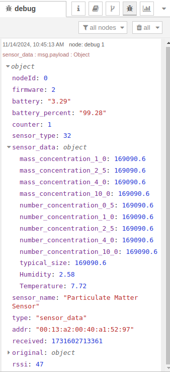
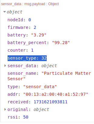
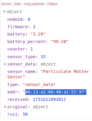
sensor_data: Sensor data is the primary message that will come from a Wireless Gateway Node. These messages can be discerned from other message types by the topic which will always be “sensor_data” To the right is an example of a Sensor Data message.
This message contains key information about the NCD sensor that generated it. It includes data such as the Node ID, Firmware Version, Battery Voltage, Battery Percentage, Counter, Sensor Type, values of the field variables the sensor is measuring and transmitting (msg.payload.sensor_data), the sensor’s Name, the MAC Address of the radio frequency module used for transmission, the precise time at which the message was received, the original message (in HEX format), and the RSSI Signal Quality (if enabled within the Wireless Gateway node).
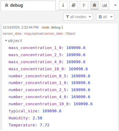
msg.payload.sensor_data: This message is present in the “sensor_data” message and can be seen in the example above. This message contains only the values of the field variables that the NCD sensor is measuring. In this example you can see that it contains the current values of the air quality, temperature and humidity values. This message is inside the property: msg.payload.sensor_data
Importing and setting up
To use this node in your current Node-RED NCD project or application, access the node repository, copy or download the JSON code, and then import the file into Node-RED. The procedure is outlined below.
Repository
Click on the following link to access the NCD Filter Node source code. NCD Filter Node Github Repository:
https://github.com/ncdcommunity/node-red-ncd-filter-node/blob/main/nodered/ncd-filter-node.json
Once the repository is open, locate the button that allows you to copy the raw code of the NCD Fliter Node. Refer to the following image for a visual reference:

Import
With the NCD Filter Node source code copied, head back to the Node-RED node editor and follow these next steps carefully:
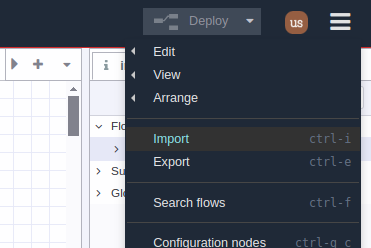
1. Go to the Main Menu (icon in the upper right corner) then click on “Import” option, as shown in picture:
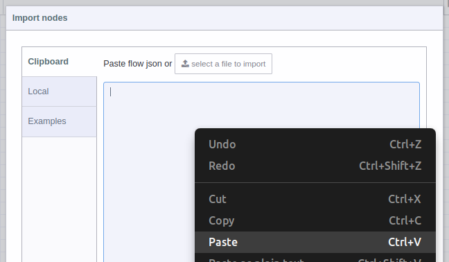
2. A text-box will be opened. Right click and paste the code you just copied from GitHub, as shown in picture:
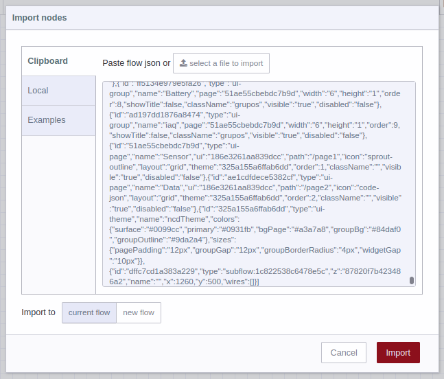
3. You should see the JSON code in text-box, now you can press the red “Import” button at the bottom right (by default the “current flow” option is selected):
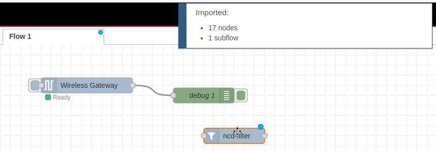
4. In the top of the Node-RED editor, you will see information of the NCD-Filter Node you just imported, and automatically you will have the node available inside the node editor, now you can position it inside the editor or workspace by left clicking:
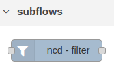
5. You may also notice that the NCD Filter Node has been added to the Subflow group in nodes palette.
Connection Flow
As mentioned earlier, this node is connected to the output terminal of the Wireless Gateway node. By default, it allows all messages to pass through.
To test the functionality of the ncd-filter node, connect a Debug node to its output, as demonstrated in the flow:

Node Properties
This node allows intuitive filtering of messages received from the Wireless Gateway node. It can be configured to either pass all messages or filter them based on specific criteria. The following filtering options are available:
To access the properties of this node, double-click on it. Below is a description of each property:

Mode: This property allows you to choose which data will flow through the node’s output terminal. The available options are as follows:
- All messages (Sensors and Modem/Gateway): Allows all messages to pass through.
- Only messages from Gateway/Modem: Allows only messages originating from the Gateway/Modem itself.
- Only messages from sensors: Filters and allows only messages originating from NCD sensors.
- Only sensor mode messages: Filters and allows only messages of a specific type, such as RUN, PGM, FLY, ACK, etc.
- Only sensor data messages: Filters messages based on the “Sensor Data” property.
- Only the values of sensor variables: Only the values of sensor variables are filtered and sent.
Sensor Type: This property must be set to a numeric value. It allows you to filter messages based on sensor type. If you have multiple sensors of the same type in your network, only messages from sensors matching the type specified in this property will flow through the output terminal. (This property is useful when you want to pass data from sensors of the same type through the output.)
Mac Address: This property must be set to a string value. It allows you to filter messages based on the sensor’s MAC address. If you have multiple sensors of the same or different types in your network, only messages from sensors with a matching MAC address specified in this property will flow through the output terminal. (This property is useful when you want to pass data from a specific sensor, regardless of its type.)
Filter examples
The following are practical examples of each filter available within the node. The filtered messages are displayed on the right side, where the corresponding filter is applied using a Debug node. The resulting messages can be viewed in the Debug window.
All messages (Sensors and Modem/Gateway)
Only messages from Gateway/Modem
Only messages from sensors
Only messages from sensors + Sensor Type
Only messages from sensors + MAC
Only sensor mode messages
Only sensor mode messages + Sensor Type
Only sensor mode messages + MAC Address
Only sensor data messages
Only sensor data messages + Sensor Type
Only sensor data messages + MAC Address
Only the values of sensor variables
Only the values of sensor variables + Sensor Type
Only the values of sensor variables + MAC Address
Multiple Node Filter Usage example
You can copy and paste, or drag and drop this node into the flow multiple times, allowing you to filter messages in different ways. For example, in a typical scenario with two NCD sensors in your network (either the same or different types), you can connect two filter nodes to the same output of the Wireless Gateway node, set the mode to “Only sensor data messages”, and configure the MAC Address property in each node to match the corresponding sensor. This way, you can filter the data from each sensor into separate nodes. The following image illustrates this example.


